AK8PCG441LNotebook PC with Built In Wireless LAN
Sony Group Corporation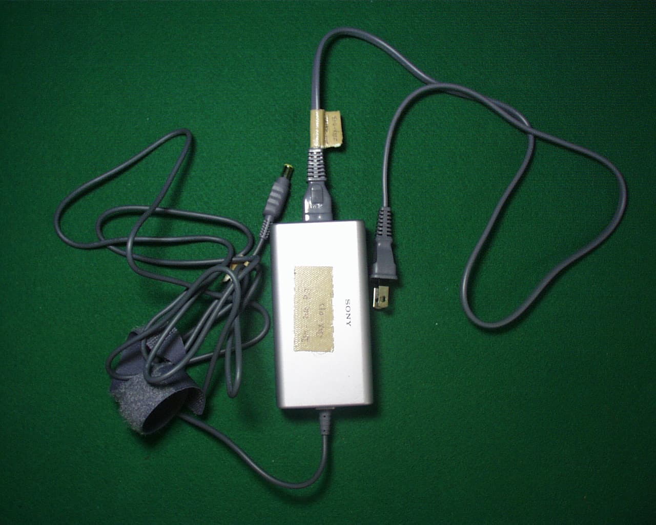
Click to zoom
Application Details
- Equipment Class
- DSS - Part 15 Spread Spectrum Transmitter
- Date of Grant
- Dec 13, 2001
- Application Purpose
- Original Equipment
- Date of Application
- Dec 13, 2001
- Equipment Note
- Notebook PC with Built In Wireless LAN
- Frequency Range
- 2412.00000000 - 2462.00000000
- Company
- Sony Group Corporation
- Country
- Japan
Documents & Files
Document Text
Text extracted from the exhibit documents filed with the FCC. Open a document above to read the original.
Users Manual
VAIO® Computer Notes on Use PCG-SRX77, PCG-SRX77P Notes on Use 2 Notice to Users © 2002 Sony Electronics Inc. All rights reserved. This manual and the software described herein, in whole or in part, may not be reproduced, translated, or reduced to any machine-readable form without prior written approval. SONY ELECTRONICS INC. PROVIDES NO WARRANTY WITH REGARD TO THIS MANUAL, THE SOFTWARE, OR OTHER INFORMATION CONTAINED HEREIN AND HEREBY EXPRESSLY DISCLAIMS ANY IMPLIED WARRANTIES OF MERCHANTABILITY OR FITNESS FOR ANY PARTICULAR PURPOSE WITH REGARD TO THIS MANUAL, THE SOFTWARE, OR SUCH OTHER INFORMATION. IN NO EVENT SHALL SONY ELECTRONICS INC. BE LIABLE FOR ANY INCIDENTAL, CONSEQUENTIAL, OR SPECIAL DAMAGES, WHETHER BASED ON TORT, CONTRACT, OR OTHERWISE, ARISING OUT OF OR IN CONNECTION WITH THIS MANUAL, THE SOFTWARE, OR OTHER INFORMATION CONTAINED HEREIN OR THE USE THEREOF. Sony Electronics Inc. reserves the right to make any modification to this manual or the information contained herein at any time without notice. The software described herein is governed by the terms of a separate user license agreement. This product contains software owned by Sony and licensed by third parties. Use of such software is subject to the terms and conditions of license agreements enclosed with this product. Some of the software may not be transported or used outside the United States. Software specifications are subject to change without notice and may not necessarily be identical to current retail versions. Updates and additions to software may require an additional charge. Subscriptions to online service providers may require a fee and credit card information. Financial services may require prior arrangements with participating financial institutions. The International ENERGY STAR® Office Equipment Program is an international program that promotes energy saving through the use of computers and other office equipment. The program backs the development and dissemination of products with functions that effectively reduce energy consumption. It is an open system in which business proprietors can participate voluntarily. The targeted products are office equipment such as computers, displays, printers, facsimiles and copiers. Their standards and logos are uniform among participating nations. ENERGY STAR i s a U .S. registered mark. Sony, DVgate, Handycam, i.LINK, Mavica, MagicGate™ Memory Stick and , Memory Stick and , MovieShaker, PictureGear, PictureToy, VAIO, and the VAIO logo are trademarks of Sony Corporation. Microsoft, Windows Media, Windows, Windows NT, and the Windows logo are As an E NERGY S TAR® Partner, Sony Corporation has determined that this product meets the E NERGY S TAR® guidelines for energy efficiency. MEMORY STICK TM Notice to Users 3 registered trademarks of Microsoft Corporation. Intel, SpeedStep, and Pentium are trademarks or registered trademarks of Intel Corporation. PS/2 is a registered trademark of IBM. Acrobat Reader, Photoshop, Photoshop Elements, and Premiere are trademarks of Adobe Systems Incorporated. PowerPanel is a trademark of Phoenix Technologies Ltd. This product incorporates copyright protection technology that is protected by method claims of certain U.S. patents and other intellectual property rights owned by Macrovision Corporation and other rights owners. Use of this copyright protection technology must be authorized by Macrovision Corporation, and is intended for home and other limited viewing uses only unless otherwise authorized by Macrovision Corporation. Reverse engineering or disassembly is prohibited. i.LINK is a trademark of Sony used only to designate that a product contains an IEEE 1394 connection. The i.LINK connection may vary, depending on the software applications, operating system, and compatible i.LINK devices. All products with an i.LINK connection may not communicate with each other. Please refer to the documentation that came with your compatible i.LINK device for information on operating conditions and proper connection. Before connecting compatible i.LINK PC peripherals to your system, such as a CD-RW or hard disk drive, confirm their operating system compatibility and required operating conditions. All other trademarks are trademarks of their respective owners. Owner’s Record The model number and serial number are located on the bottom of your Sony VAIO Notebook. Refer to the model and serial number when you call your Sony Service Center. Model Numbers: PCG-441L Serial Number:________________________ Registering Your Notebook Sony is proud to offer you state-of-the-art multimedia computing technology. In order for Sony to provide you with the highest caliber of technical support and inform you of new product developments and upgrades, please take a few moments to register your notebook. Safety Information WARNING ❑ To prevent fire or shock hazard, do not expose your notebook computer to rain or moisture. ❑To avoid electrical shock, do not open the cabinet. Refer servicing to qualified personnel only. ❑Never install modem or telephone wiring during a lightning storm. ❑Never install telephone jacks in wet locations unless the jack is specifically designed for wet locations. Notes on Use 4 ❑Never touch uninsulated telephone wire or terminals unless the telephone line has been disconnected at the network interface. ❑Use caution when installing or modifying telephone lines. ❑Avoid using the modem during an electrical storm. ❑Do not use the modem or a telephone to report a gas leak in the vicinity of the leak. ❑A socket outlet should be as close as possible to the unit and easily accessible. ❑i.LINK, PC Card, and USB connectors are not supplied with Limited Power Sources. AVERTISSEMENT ❑Pour prévenir tout risque d’incendie ou d’électrocution, garder cet appareil à l’abri de la pluie et de l’humidité. ❑Pour prévenir tout risque d’électrocution, ne pas ouvrir le châssis de cet appareil et ne confier son entretien qu’à une personne qualifiée. ❑Ne jamais eff…
Text truncated - open the document above for the full version.
Cover Letter(s)
A- PEX INTERNATIONAL CO., LTD. •HEAD OFFICE •4383-326 Asama-cho, Ise-shi, Mie-ken 516-0021 Japan TEL:0596-24-6717/FAX:0596-24-8020 Date:12 December, 2001 Re: Sony Corporation FCC ID: AK8PCG441L Dear Mr. Timothy Johnson, Please find the following replies to your comments dated 7 December, 2001; 1) Please find the photos in the filing. 2) Please find the photos in the filing. However, Sony purchases this LAN Card from Lucent. So, Sony wants to be them confidential. Please find the confidential request letter in the filing. 3) We uploaded operational description and photos of test configuration in the filing. 4) Please find the revised Form 731 in the filing. 5) “1.64dBi” is not correct. “1.64” is absolute value of antenna gain. 1.64 is equal to 2.14dBi. 6) Sony has already tested for Subpart B as Class B device for Personal Computer. We already submitted the label location and label drawing in the filing. For Class B, please find the uploaded test report. 7) The reason why there is approximately 5 dB difference between the peak conducted power (A16) and the peak output power (A9) seems that there is uncertain factors such as the equipment with antenna mounted and site attenuation at the radiated emission test. Guidance on Measurements for Direct Sequence Spread Spectrum System of FCC Public Notice require that the peak output power should be measured at radiated emission if it cannot be measured at conducted emission. Thus, we regard the conducted emission test result as the official data, and the radiated emission test data, which was measured the equipment with antenna mounted, is attached to the test report as reference. 8) The test data at the 2390.0MHz and 2483.5MHz band edge is included in the following page of Appendix of Test Report No. 22DE0015-YW-1: 2390.0MHz: A21 Data No. 6 2483.5MHz: A23 Data No. 6 Kanako Sanda A-Pex Int ernational Co., Ltd.
Cover Letter(s)
American Telecommunications Certification Body Inc. 6731 Whittier Ave, McLean, VA 22101 December 7, 2001 RE: Sony FCC ID: AK8PCG441L After a review of the submitted information, I have a few comments on the above referenced Application. 1) Please provide clearer photographs for the top of computer, bottom of computer, & top view of LAN module. The supplied photographs were either too dark or blurry. 2) Please provide the following additional photographs: the back of the computer, top view of LAN module with shields removed, & bottom view of LAN module with shields removed. 3) Please upload an exhibit for the operational description and test configuration photographs. 4) The power listed on the 731 should be listed in the same manner as the limit set by the FCC (i.e. ERP, EIRP, or conducted). For this application, the power listed on the 731 form should be specified as the maximum conducted power measured (14.7 dBm = 29.5 mW) and not the EIRP measurement. Also, please list the frequencies as 2412-2462 MHz on the 731. Please provide a corrected 731 form. 5) The test report states that the integral antenna is 2.14 dBi gain, while the MPE calculations & Peak Output Radiated use 1.64 dBi gain. Please comment and/or correct affected items. 6) The EUT consists of a PC + transmitter integrated together and is subject to the applicable requirements of both. The report provided for certification only covers the transceiver portion of the device. However to meet all the applicable requirements for this device, the laptop should have also been tested (with the transceiver installed) with all ports fully populated (i.e. the additional ethernet, telephone, headphone, etc.) to meet the DoC requirements as a personal computer. Please confirm that the EUT has been properly evaluated and tested in a fully populated configuration (and with the transceiver installed) or provide a copy of the DoC report. 7) There is approximately 5 dB difference between the peak conducted power (A16) and the peak output radiated power (A9) (measured and corrected using 2.14 dBi). Please explain. 8) The maximum peak radiated power of the fundamental is shown in A9. However, please provide further information to show compliance with the restricted band at the 2.4835 GHz bandedge. Timothy R. Johnson Examining Engineer mailto: [email protected] The items indicated above must be submitted before processing can continue on the above referenced application. Failure to provide the requested information may result in application termination. Correspondence should be considered part of the permanent submission and may be viewed from the Internet after a Grant of Equipment Authorization is issued. Please do not respond to this correspondence using the email reply button. In order for your response to be processed expeditiously, you must submit your documents through the AmericanTCB.com website. Also, please note that partial responses increase processing time and should not be submitted. Any questions about the content of this correspondence should be directed to the sender.
Operational Description
Test report FCC ID : AK8PCG441L Our reference : 22DE0015-YW-1 Page: 3 of 15 Issued date: December 3, 2001 A-pex International Co., Ltd. YOKOWA LAB. 108 Yokowa-cho, Ise-shi, Mie-ken 516-1106 JAPAN Telephone:int +81 596 39 1485 Facsimile: int +81 596 39 0232 1 GENERAL INFORMATION APPLICANT: Sony Corporation ADDRESS: 6-7-35 Kitashinagawa, Shinagawa-ku, Tokyo 141-0001 Japan TEL: 81-3-5795-8716 FAX: 81-3-5795-8981 REGULATION(S): FCC Part15 Subpart C, Section 15.247 MODEL NUMBER: PCG-441L SERIAL NUMBER: 013 (Radiated and AC Main Conducted Emissions tests) 001 (Antenna connector Conducted tests) KIND OF EQUIPMENT: Notebook Computer (Wireless LAN built in PC) TESTED DATE: November 19-22, 2001 RECEIPT DATE OF SAMPLE : November 19, 2001 REPORT FILE NUMBER: 22DE0015-YW-1 TEST SITE: A-PEX Yokowa No.3 Open Test Sites The ORiNOCO Mini PCI radio card is a full-featured, Wi-Fi-compliant wireless device that uses the Mini PCI form factor. The module functions at 2.4 GHz, with a bandwidth of 11 Mbps, and range of up to 1200 feet. It is fully compatible with the entire ORiNOCO line of infrastructure produces for home, office, outdoor and public hot-spot environments. The Mini PCI radio also works with other Wi-Fi-compliant wireless networking systems. Integration into OEM Devices Ideally suited for notebooks, Web pads, Internet appliances and other mobile data applications, the Mini PCI card is only 51 x 60mm in size and weighs 15 grams. The Mini PCI gives manufacturers a great deal of freedom in system design and antenna placement. It can be embedded or designed to be an optional dealer-added feature. ORiNOCO Mini PCI is supported by a complete set of drivers and networking tools to support operating systems including Windows ME, 98, 2000 and Linux. The card is available in two versions, one with 64 WEP encryption and one with 128 bit RC4 encryption. In the automatic mode, the ARS mechanism will select the best possible speed for every data path. This means that the actual speed the mobile clients will use when talking to an Access Point can be different for different stations within one cell. Integration support Lucent provides extensive technical documentation on integration issues like optimal antenna design, customized drivers and management software as well as multi language support for manuals and help files. Echo robustness The delay spread robustness in the IEEE 11 and 5.5 Mbit/s mode is lower than in the IEEE 2 and 1 Mbit/s modes, because delay spread robustness is traded against more sophisticated modulation techniques. Privacy The ORiNOCO Mini PCI Card supports 64 bit WEP as a standard. This means that 64 WEP is used to encrypt the payload data in a message when the end user chooses to run this level of privacy. WEP, which is defined in the IEEE 802.11b standard, uses a 40 bit secret key and a 24 bit Initialization Vector (IV): a 24 bit value unique to a message, which is included in plain text in that message. The IV is included to make sure that two identical plain text messages result in two different encrypted messages. The ORiNOCO/ Mini PCI Card is also released with 128 RC4. This product uses the RC4 encryption algorithm with a 104 bit secret key and a 24 bit IV. Mini PCI Form Factor Radios for Wireless Networking OEMs ORiNOCO TM Mini PCI THE NEW WAVELAN YOUR MOBILE BROADBAND CONNECTION ORiNOCO Mini PCI Card Specifications Frequency Range2400 2462 mHz Number of Selectable Channels11 Modulation TechniqueDirect Sequence Spread Spectrum (CCK, DQPSK, DBPSK) StandardIEEE 802.11b, Mini PCI V1.0 Security64 WEP or 128 RC4 Spreading11 chip Barker sequence Bit Error rateBetter than 10 -5 Media Access ProtocolCSMA/CA (Collision Avoidance) with ACK InterfaceMiniPCI V1.0 PCB Dimension Length:59.75 mm Width: 50.95mm Range (meter/feet)Standard Low SpeedStandard SpeedMedium SpeedHigh Speed (1 Mbit/s)(2 Mbit/s)(5.5 Mbit/s)(11 Mbit/s) Open environment550 m (1750 ft)400 m (1300 ft)270 m (855 ft)160 m (525 ft) Semi-Open environment115 m (375 ft)90 m (300 ft)70 m (230 ft)50 m (165 ft) Closed environment50 m (165 ft)40 m (130 ft)35 m (115 ft)25 m (80 ft) Transmitter output power15 dBm15 dBm15 dBm15 dBm Min. receive level @BER 10^ -5 -94 dBm-91 dBm-87 dBm-82 dBm Delay spread robustness in nanoseconds500 ns400 ns225 ns65 ns Max. Power ConsumptionDoze Mode 16 mA Receive Mode 250mA Transmit Mode 350 mA EnvironmentalThe ORiNOCO Mini PCI Card passes the environmental tests as specified in “Mini PCI Specification, October 1999, Section 5.6 Thermal Guidelines”. Operating temperature0 to 60°C ambient temperature Storage temperature-20 to 75°C ambient temperature Operating humidity95% maximum (non condensing) Storage humidity95% maximum (non condensing) W ired b ackb o n e Basic ORiNOCO Mini PCI Configuration ORiNOCO Mini PCI Card Specifications(continued) Barometric pressure740 to 1050 HPa (storage and operating) Operating System CompatibilityWindows 98, ME and 2000.(NDIS5 Miniport Driver), Linux WHQLDevice WHQL sytem to be certified in co-operation with the OEM manufacturer RegulationsEurope: R&TTE Dir. 1999/5/EC USA: FCC 47 CFR, Part15.247 Canada:ISC RSS139 EnvironmentDelay Spread Office (one room)30 nsec Office40 – 150 nsec Airport120 nsec Warehouse130 nsec Shopping mall90 – 200 nsec Factory300 – 500 nsec Net Throughput11Mb 11Mb11Mb (payload, excluding headers etc)High SpeedMedium SpeedStandard Speed (11 Mbit/s)(5.5 Mbit/s) (2 Mbit/s) Station-to-station (TCP/IP) Peer to Peer5.04 Mbit/s3.44 Mbit/s1.59 Mbit/s Peer to Peer (+WEP128)4.51 Mbit/s3.44 Mbit/s1.59 Mbit/s via AP (both wireless)2.85 Mbit/s via AP (both wireless) (+WEP128)2.62 Mbit/s via AP (one on Ethernet)4.66 Mbit/s via AP (one on Ethernet) (+WEP128)4.11 Mbit/s Frequency Channels Channel Number12 3 4 5 6 78 91011 Channel Frequencies (MHz) 2412 241724222427243224372442 24472452 24572462 For additional information, please contact your Lucent Technologies Sales Representative. You can also visit our web site at http://www.lucent.com or call 1-800-928-3526. ORiN…
Text truncated - open the document above for the full version.
RF Exposure Info
RF Exposure Statement No. : 22DE0015-YW-1 Applicant: Sony Corporation Type of Equipment: Wireless LAN builtin Personal Computer Model No.: PCG-441L FCC ID: AK8PCG441L A-PEX International Co., Ltd. YOKOWA LAB. 108 Yokowa-cho, Ise-shi, Mie-ken 516-1106 JAPAN Telephone:int +81 596 39 1485 Facsimile: int +81 596 39 0232 Page 1 FCC Radiation Exposure Statement: Sony Corporation Model : PCG-441L complies with FCC radiation exposure requirement specified in the FCC Rules 15.247(b)(4). Notice in Installation Manual FCC Radiation Exposure Statement: This equipment complies with FCC radiation exposure limits set forth for an uncontrolled environment. This equipment should installed and operated with minimum distance 20cm between the radiator and your body(excluding extremities : hands, wrists, and feet). RF Exposure Calculations: The following information provides the minimum separation distance for the highest gain antenna provided with the “PCG-441L” as calculated from FCC OET 65 Appendix B, Table (B) Limits for General Population / Uncontrolled Exposure. This calculation is based on the highest EIRP possible from the system, considering maximum power and antenna gain, and considering a 1.0m W/cm^2 uncontrolled exposure limit. The Fires formula used was: S = (P * G) / (4* * r^2) or r = (P * G) / (4 * * S) Where S = 1.0 mW/cm^2 for 2400 MHz P = 29.5 mW (Maximum Conducted Power) G = 1.64(Half wave dipole antenna gain : Converted absolute value) r = Minimum safe distance from antenna (cm) For: PCG-441L r = 2.0 cm
Test Report
Test report FCC ID : AK8PCG441L Our reference : 22DE0015-YW-1 Page: 2 of 15 Issued date: December 3, 2001 A-pex International Co., Ltd. YOKOWA LAB. 108 Yokowa-cho, Ise-shi, Mie-ken 516-1106 JAPAN Telephone:int +81 596 39 1485 Facsimile: int +81 596 39 0232 Table of Contents Page 1 GENERAL INFORMATION3 1.1 Tested Methodology4 1.2 Test Facility4 2 PRODUCT DESCRIPTION5 2.1Test system Details5 3 SYSTEM TEST CONFIGURATION6 3.1 Justification6 3.2.Configuration of Tested System6 4 MEASUREMENT UNCERTAINTY7 5 TEST INSTRUMENTS8 6 SUMMARY OF TEST9 6.1 §15.207 Conducted Emissions9 6.2 §15.247(a)(2)6dB Bandwidth9 6.3 §15.247(b) Maximum Peak Out Put Power(Radiated and Conducted)10 6.4 §15.247(c) Out of Band Emissions(Radiated)11 6.5 §15.247(c) Out of Band Emissions(Conducted)11 6.6 §15.247(d) Power Density(Conducted)12 6.7 §15.247(e) Processing Gain12 Photographs of test setup 13-14 APPENDIX15 Test dataA1toA40 Test report FCC ID : AK8PCG441L Our reference : 22DE0015-YW-1 Page: 3 of 15 Issued date: December 3, 2001 A-pex International Co., Ltd. YOKOWA LAB. 108 Yokowa-cho, Ise-shi, Mie-ken 516-1106 JAPAN Telephone:int +81 596 39 1485 Facsimile: int +81 596 39 0232 1 GENERAL INFORMATION APPLICANT: Sony Corporation ADDRESS: 6-7-35 Kitashinagawa, Shinagawa-ku, Tokyo 141-0001 Japan TEL: 81-3-5795-8716 FAX: 81-3-5795-8981 REGULATION(S): FCC Part15 Subpart C, Section 15.247 MODEL NUMBER: PCG-441L SERIAL NUMBER: 013 (Radiated and AC Main Conducted Emissions tests) 001 (Antenna connector Conducted tests) KIND OF EQUIPMENT: Notebook Computer (Wireless LAN built in PC) TESTED DATE: November 19-22, 2001 RECEIPT DATE OF SAMPLE : November 19, 2001 REPORT FILE NUMBER: 22DE0015-YW-1 TEST SITE: A-PEX Yokowa No.3 Open Test Sites Test report FCC ID : AK8PCG441L Our reference : 22DE0015-YW-1 Page: 4 of 15 Issued date: December 3, 2001 A-pex International Co., Ltd. YOKOWA LAB. 108 Yokowa-cho, Ise-shi, Mie-ken 516-1106 JAPAN Telephone:int +81 596 39 1485 Facsimile: int +81 596 39 0232 1.1 Tested Methodology The measurement was performed according to the procedures in ANSI C63.4(1992). 1.2 Test Facility The open area site measurement facilities used to collect the radiated data are located at 108, Yokowa-cho, Ise-shi, Mie-ken, 516-1106 Japan. These sites have been fully described in reports submitted to the FCC office. No.1 and No.3 test site has filed to the FCC on September 12, 2000 as number: 90412 and is accepted by Industry Canada on May 01, 2001 as number IC2973-3. Test report FCC ID : AK8PCG441L Our reference : 22DE0015-YW-1 Page: 5 of 15 Issued date: December 3, 2001 A-pex International Co., Ltd. YOKOWA LAB. 108 Yokowa-cho, Ise-shi, Mie-ken 516-1106 JAPAN Telephone:int +81 596 39 1485 Facsimile: int +81 596 39 0232 2 PRODUCT DESCRIPTION Sony Corporation, Model PCG-441L (referred to as the EUT in this report) is a Notebook Computer. The specification is as following : LAN Module Frequency characteristies: 2412MHz through 2462MHz No. of channels / channel spacing : 11 channels / 5MHz channel spacing Modulation: DSSS:Direct sequence spread spectrum.(IEEE 802.11b) Antenna type: /4 monopole antenna (Integral) Antenna Gain: 2.14dBi (Peak) I/F: PCMCIA-bus *FccPart15.31(e) The host device PCG-441L provide the LAN Module with stable power supply(DC:3.3V), and the LAN Module complies power supply regulation. *FccPart15.203 Antenna requirement Wireless LAN Module and its antenna comply with this requirement since they are built in host device PCG-441L when they are put up for sale and they are used with a particular antenna connector. 2.1 Test System Details Model FCC ID Description (1)Sony Corporation AK8PCG441LNotebook Computer M/N: PCG-441L(Wireless LAN built in PC) S/N: 013 (Radiated and AC Main Conducted Emissions tests) 001 (Antenna connector Conducted tests) *FccPart15 Subpart B Class B Digital Device DOC (2) Sony Corporation DOC AC Adapter M/N: PCGA-AC16V3 S/N: 0110 A 0000069P (Radiated and AC Main Conducted Emissions tests) 0110 A 0000048P (Antenna connector Conducted tests) Test report FCC ID : AK8PCG441L Our reference : 22DE0015-YW-1 Page: 6 of 15 Issued date: December 3, 2001 A-pex International Co., Ltd. YOKOWA LAB. 108 Yokowa-cho, Ise-shi, Mie-ken 516-1106 JAPAN Telephone:int +81 596 39 1485 Facsimile: int +81 596 39 0232 3 SYSTEM TEST CONFIGURATION 3.1 Justification The system was configured in typical fashion (as a customer would normally use it) for testing. Test mode : Transmitting mode Performed the test about channels 1(low), 6(mid) and 11(high) among 11 channels of all Carrier frequencies. Receiving mode 3.2 Configuration of Tested System AC 120V/60Hz Wooden table (1)EUT (2) * Cabling was taken into consideration and test data was taken under worst case conditions. List of cables used No.NameLength (m)ShieldRemark AC Power Cable0.75NPolyvinyl chloride DC Power Cable2.0NPolyvinyl chloride Test report FCC ID : AK8PCG441L Our reference : 22DE0015-YW-1 Page: 7 of 15 Issued date: December 3, 2001 A-pex International Co., Ltd. YOKOWA LAB. 108 Yokowa-cho, Ise-shi, Mie-ken 516-1106 JAPAN Telephone:int +81 596 39 1485 Facsimile: int +81 596 39 0232 4 Measurement Uncertainty Conducted Emission Test The measurement uncertainty (with a 95% confidence level) for this test was ±2.0dB. The data listed in this test report may exceed the test limit because it does not have enough margin (more than 2.0dB). The data listed in this test report has enough margin, more than 2.0dB. Radiated Emission Test The measurement uncertainty (with a 95% confidence level) for this test using Biconical antenna is4.4dB. The measurement uncertainty (with a 95% confidence level) for this test using Logperiodic antenna is4.8dB. The measurement uncertainty (with a 95% confidence level) for this test using Horn antenna is5.8dB. The data listed in this test report may exceed the test limit because it does not have enough margin. The data listed in this test report has enough margin, more than site margin. Test report FCC ID : AK8PCG441L Our referen…
Text truncated - open the document above for the full version.
Test Report
JAPAN QUALITY ASSURANCE ORGANIZATION 21-25, KINUTA 1-CHOME, SETAGAYA-KU, TOKYO 157-8573 JAPAN PHONE (03) 3416-0111, TELEX 242-2531 JQA J FAX (03) 3416-9691 JQA APPLICATION NO. : 400-10583 Issue Date : December 3, 2001 Page 1 of 27 EMI TEST REPORT JQA APPLICATION NO. : 400-10583 Model No. : PCG-441L Type of Equipment : Notebook Personal Computer Regulations Applied : CFR 47 FCC Rules and Regulations Part 15 FCC ID : N/A(Declaration of Conformity) Applicant : Sony Electronics Inc. Address : 680 Kinderkamack Road, Oradell NJ 07649 U.S.A Manufacturer : Sony Corporation Address : 6-7-35 Kitashinagawa, Shinagawa-ku, Tokyo 141-0001, Japan Final Judgment : Passed TEST RESULTS IN THIS REPORT are obtained in use of equipment that is traceable to National Institute of Advanced Industrial Science and Technology (AIST) of Japan and Communication Research Laboratory (CRL) of Japan. This report should not be reproduced except in full, without the written approval of JQA EMC Engineering Dept. Testing Div. This report must not be used by the client to claim product endorsement by NVLAP or any agency of the U.S. Government. NVLAP Lab. Code : 200189-0 C O P Y JQA Application No. :400-10583 FCC ID :N/A(DoC) Model No. :PCG-441L Issue Date :December 3, 2001 Standard :CFR 47 FCC Rules Part 15 Page 2 of 27 JAPAN QUALITY ASSURANCE ORGANIZATION TABLE OF CONTENTS Page 1 Documentation 1.1 Test Regulation 3 1.2 General Information 3 1.3 Test Condition 4 - 6 1.4 EUT Modifications 7 1.5 Test results / Uncertainty 8 1.6 Summary 9 1.7 Test Configuration / Operation of EUT 10 – 11 1.8 EUT Arrangement (Drawings) 12 1.9 Preliminary Test and Test-setup (Drawings) 13 - 15 1.10 EUT Arrangement (Photographs) 16 - 21 2 Test Data 2.1 AC Power Line Conducted Emission 0.45 MHz – 30 MHz 22 - 23 2.2 Radiated Emission (Electric Field) 30 MHz – 1000 MHz 24 - 27 2.3 Radiated Emission (Electric Field)Above 1 GHz 26 - 27 C O P Y JQA Application No. :400-10583 FCC ID :N/A(DoC) Model No. :PCG-441L Issue Date :December 3, 2001 Standard :CFR 47 FCC Rules Part 15 Page 3 of 27 JAPAN QUALITY ASSURANCE ORGANIZATION 1. DOCUMENTATION 1.1 TEST REGULATION FCC Rules and Regulations Part 15 Subpart A and B (June 23, 1989) Class B Digital Device. Test procedure AC power line conducted emission and radiated emission tests were performed According to the procedures in ANSI C63.4-1992. 1.2 GENERAL INFORMATION 1.2.1 Test facility : 1) Test Facility located at EMC Engineering Dept. Testing Div. : No.2 and 3 Anechoic Chambers( 3 meters Site ). FCC filing No. : 31040/SIT 1300F2 2) EMC Engineering Dept. Testing Div. is recognized under the National Voluntary Laboratory accreditation Program for satisfactory compliance established in title 15, Part 285 Code of Federal Regulations. NVLAP Lab Code : 200189-0 (Effective through : June 30, 2002) 1.2.2 Description of the Equipment Under Test (EUT) : 1) Type of Equipment : Notebook Personal Computer 2) Product Type : Prototype 3) Category : Class B Digital Device 4) EUT Authorization : Declaration of Conformity 5) FCC ID : N/A 6) Trade Name : SONY 7) Model No. : PCG-441L 8) Fundamental Frequency Generated/Operated In the EUT : 2.483GHz, 800.0MHz, 650.0MHz, 550.0MHz, 100.0MHz, 48.0MHz, 33.0MHz, 25.0MHz, 24.576MHz 20.0MHz, 16.0MHz, 14.318MHz, 10.0MHz, 32.768kHz 9) Highest Frequency Used in the EUT : 2.483GHz 10) Serial No. : - 11) Date of Manufacture : - 12) Power Rating : 16VDC The EUT was operated with the AC adaptor (Model:PCGA-16V3, Input:100-240VAC 50/60Hz, Output:16.0VDC by Sony). 13) EUT Grounding : None 1.2.3 Definitions for symbols used in this test report : x - indicates that the listed condition, standard or equipment is applicable for this report. - indicates that the listed condition, standard or equipment is not applicable for this report. C O P Y JQA Application No. :400-10583 FCC ID :N/A(DoC) Model No. :PCG-441L Issue Date :December 3, 2001 Standard :CFR 47 FCC Rules Part 15 Page 4 of 27 JAPAN QUALITY ASSURANCE ORGANIZATION 1.3 TEST CONDITION 1.3.1 The measurement of the AC Power Line Conducted Emission x - was performed in the following test site. - was not applicable. Test location : Safety Testing Center EMC Engineering Dept. Testing Div. 21-25, Kinuta 1-chome, Setagaya-ku, Tokyo 157-8573, Japan x - Shielded Enclosure - Anechoic Chamber No. 2 (portable Type) Used test instruments : Type Model No. Manufacturer Serial No. Last Cal. Interval x - Test Receiver ESH-2 Rohde & Schwarz 880370/016 Jun. 2001 1 Year - Test Receiver ESH-3 Rohde & Schwarz 881460/035 May. 2001 1 Year - Test Receiver ESHS 10 Rohde & Schwarz 835871/004 May. 2001 1 Year x - LISN(for Peripheral) KNW-407 Kyoritsu Electrical 8-833-6 Apr. 2001 1 Year x - LISN(for EUT) KNW-407 Kyoritsu Electrical 8-855-2 Apr. 2001 1 Year - LISN KNW-407 Kyoritsu Electrical 8-757-1 Apr. 2001 1 Year x - RF Cable 3D-2W Fujikura 155-21-006E0 Apr. 2001 1 Year - RF Cable 3D-2W Fujikura 155-21-007E0 Apr. 2001 1 Year x - 50ohm Termination - SUHNER 154-06-501E0 Jan. 2001 1 Year - 50ohm Termination - SUHNER 154-06-502E0 Jan. 2001 1 Year C O P Y JQA Application No. :400-10583 FCC ID :N/A(DoC) Model No. :PCG-441L Issue Date :December 3, 2001 Standard :CFR 47 FCC Rules Part 15 Page 5 of 27 JAPAN QUALITY ASSURANCE ORGANIZATION 1.3.2 The measurement of the Radiated Emission(30 MHz – 1000 MHz) x - was performed in the following test site. - was not applicable. Test location : Safety Testing Center EMC Engineering Dept. Testing Div. 21-25, Kinuta 1-chome, Setagaya-ku, Tokyo 157-8573,…
Text truncated - open the document above for the full version.
Contact Information
Applicant
Kazuyuki Hori(Chief EMC/RF Compliance Specialist)
Technical Contact
A-Pex International Co., Ltd.Naoki Sakamoto
[email protected]+81-596-39-1485
108 Yokowa-cho · Ise-shi, Mie-ken · Japan
Non-Technical Contact
A-Pex International Co., Ltd.Kanako Sanda
[email protected]+81-596-24-6717
Test Firm
UL Japan, Inc.Kazunori Nishimura
Technical Specifications
| # | Rule Parts | Frequency Range | Power Output |
|---|---|---|---|
| 1 | 15C | 2.41 GHz - 2.46 GHz | 29.50 mW |
Other Applications from Sony Group Corporation
AK8WW81782
Aug 21, 2026Radio Equipment
Equipment Class
DSS - Part 15 Spread Spectrum TransmitterAK8CFIZCP2
Aug 03, 2026Wireless Controller
Equipment Class
DSS - Part 15 Spread Spectrum TransmitterAK8OEV321MUH
Apr 14, 2026LCD Monitor
Equipment Class
JAD - Part 15 Class A Digital DeviceAK8OEV431MUH
Apr 14, 2026LCD Monitor
Equipment Class
JAD - Part 15 Class A Digital DeviceAK8OEV271MUH
Apr 14, 2026LCD Monitor
Equipment Class
JAD - Part 15 Class A Digital Device