AK8PCG492LPCG-492L Notebook computer with WLAN
Sony Group Corporation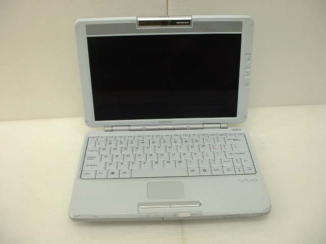
Click to zoom
Application Details
- Equipment Class
- DTS - Digital Transmission System
- Date of Grant
- Aug 26, 2003
- Application Purpose
- Original Equipment
- Date of Application
- Aug 26, 2003
- Equipment Note
- PCG-492L Notebook computer with WLAN
- Frequency Range
- 2412.00000000 - 2462.00000000
- Company
- Sony Group Corporation
- Country
- Japan
Documents & Files
Document Text
Text extracted from the exhibit documents filed with the FCC. Open a document above to read the original.
Users Manual
T60H677.02 WLAN 802.11b/g User Manual Chapter 1 About the AMBIT WLAN 802.11b/g device............................................. 3 1-1 Introduction .......................................................................................................... 3 1-2 Using a Wireless Local Area Network ................................................................. 3 1-3 Features and Requirements................................................................................... 4 Chapter 2 Network Configuring and Planning ............................................................ 5 2-1 Ad-Hoc Network................................................................................................... 5 2-2 Access Point (Infrastructure) Network ................................................................. 6 Chapter 3 Atheros Client Utility Installation............................................................... 7 3-1 Atheros Client Utility Installation......................................................................... 7 Chapter 4 Atheros Client Utility (ACU) Configuration ............................................ 10 4-1 Atheros Client Utility icon.................................................................................. 10 4-2 Current Status Tab .............................................................................................. 11 4-3 Profile Management ........................................................................................... 13 4-3-1 Create or Modify a Profile ...................................................................... 14 4-3-2 Security Settings in Profile Management................................................ 16 4-3-3 Advanced settings in Profile Management.............................................. 20 4-4 Diagnostic Tab .................................................................................................... 21 4-5 Action Menu ....................................................................................................... 22 4-5-1 Enable/Disable Radio .............................................................................. 22 4-5-2 Enable/Disable Tray Icon ........................................................................ 22 Chapter 5 Wireless Configuration using Windows XP..................................................... 23 5-1 Configuring Your Wireless Networking Settings ............................................... 23 5-2 Advanced Wireless Settings................................................................................ 23 5-3 Disabling the Radio ............................................................................................ 24 5-4 Help and Support Information ............................................................................ 24 Appendix A - Atheros Client Utility Uninstall Process .................................................... 25 Appendix B - Glossary...................................................................................................... 28 Appendix C – Wireless Notice.......................................................................................... 29 Chapter 1 About the AMBIT WLAN 802.11b/g device 1-1 Introduction The AMBIT WLAN 802.11b/g device allows you to access Wireless Local Area Networks (WLANs), share a local printer and files with others in your network, access the Internet, and roam about the office—wirelessly. This wireless Local Area Network solution is designed for both large and small businesses, and it is scalable so that you can add users and new network features as your networking needs grow. The AMBIT WLAN 802.11b/g device is a 2.4Ghz WLAN technology that will operate with at a maximum data rate of 11Mbps with 802.11b and maximum data rate of 54Mbps with 802.11g wireless networks. The AMBIT WLAN 802.11b/g device will automatically detect and seamlessly roam between both 802.11b and 802.11g wireless networks. 1-2 Using a Wireless Local Area Network A wireless LAN provides the same functionality of a wired network, but it eliminates the need to install networking cables and other networking equipment. Not only is a wireless LAN easier to deploy, but it also allows for mobility through “roaming.” For example the AMBIT WLAN 802.11b/g device can roam from a conference room to an office without being disconnected from the network. 1-3 Features and Requirements The AMBIT WLAN 802.11b/g device includes the following features: Wireless Features • Support for the IEEE 802.11b standard • Support for the IEEE 802.11g standard • Operates within the 2.4-GHz band • Maximum data rate of up to 11 Mbps (802.11b) • Maximum data rate of up to 54 Mbps (802.11g) Interoperability • WiFi certified at 2.4GHz to ensure wireless interoperability with other WiFi (802.11b) certified devices. Security • Cisco Client Extension compatibility (including LEAP) • Wired Equivalent Privacy (WEP) encryption, operating with 64bit, 128bit or 152 bit encryption • AES-CCM Encryption support • Support for Windows 802.1X supplicants Chapter 2 Network Configuring and Planning A wireless LAN can be configured for two different modes of operation. While each method has its advantages, one may be better suited for your needs. Review the following configurations to determine which mode is best for you. • Ad-Hoc Network • Access Point (Infrastructure) Network 2-1 Ad-Hoc Network An Ad-Hoc network is the simplest to deploy and is ideal for small offices. Ad-Hoc wireless networks can be comprised of two or more wireless client configured to communicate with one another. All Ad-hoc clients communicate directly with each other without using an access point (AP). As a user on this type of network, you are able to quickly build up a wireless network in order to share files with other employees, print to a shared office printer, and access the Internet through a single shared connection. Ad-hoc networking is cost effective, because no other devices components …
Text truncated - open the document above for the full version.
Cover Letter(s)
American Telecommunications Certification Body Inc. 6731 Whittier Ave, McLean, VA 22101 August 5, 2003 RE: FCC ID: AK8PCG492L Attention: Kanako Sanda / Yoshiko Mizuta I have a few comments on this Application. 1. Please provide a drawing or photo of where the card is located in the laptop. - 2. Please note that the draft document “Operational Description.pdf” shows a reported SAR of 0.0687w/kg and the SAR report shows 0.101w/kg. Please make documentation consistent. Please correct documents to reflect the actual measured SAR levels. - 3. Please note that the maximum conducted power measured during SAR testing is 22dBm (158mW OFDM modulation on page 17 of SAR report) and the maximum measured conducted power during the EMC testing was 19.5dBm (89mW on page 37 of EMC report). Please note that while there is sometimes an allowable variance of up to 3dB for EIRP powers between the EMC and SAR reports, the FCC requires that the maximum variance between the maximum conducted power in the EMC report and the maximum conducted power in the SAR report be no more than 5%. Please note that the variance between the SAR report values and the EMC report values in your application is almost 45%. This is not acceptable. Please provide EMC and SAR reports that are within 5% of each other for maximum conducted power measurements. - 4. While I see that before and after conducted power measurements were made and provided on page 17 of the SAR report, please explain why power drift was provided only on the validation plots and not provided on the data plots are requested by the FCC. - 5. Please note that the manual indicates that this device is for use in the EU also. Please note that, as you may know, the frequency channels used in the EU are different that in the US (i.e. 2412 to 2462 MHz operation only in the US). Please also note that the FCC has stated that under no circumstance can any other channels than channels 1 through 11 be used in the US, and under no circumstance can selection of any other channels than these be possible for a device used in the US. Please confirm that there is no software or hardware switch, setting or other capability that will allow the selection of channels 12 or higher in this device. - 6. Please note that Sony not Hewlett Packard is the grantee of this device. Consequently Sony is the responsible party. Please note that on page 29 of the manual you state, “The FCC requires the user to be notified that any changes or modifications made to device that are not expressly approved by the Hewlett-Packard Company may void the user's authority to operate the equipment.” This is not a proper statement as HP has no authority over this device. Please correct the non-modification statement by replacing Hewlett Packard with Sony’s name. - Dennis Ward mailto:[email protected] The items indicated above must be submitted before processing can continue on the above referenced application. Failure to provide the requested information may result in application termination. Correspondence should be considered part of the permanent submission and may be viewed from the Internet after a Grant of Equipment Authorization is issued. Please do not respond to this correspondence using the email reply button. In order for your response to be processed expeditiously, you must submit your documents through the AmericanTCB.com website. Also, please note that partial responses increase processing time and should not be submitted. Any questions about the content of this correspondence should be directed to the sender.
Cover Letter(s)
20 August, 2003 Subject : FCC ID: AK8PCG492L Dear Mr. Dennis Ward, Regarding to your comments for FCC ID: AK8PCG492L in August 5, 2003, please find the following replies; 1. Please see Page.2 of Antenna Information. 2. Please see the revised Operational Description, page 10 on the website. 3. Please find Data of Peak output power(Conducted) on the web site. 4. Under consideration. 5. Please see the revised Technical Specification, page 5 on the website. 6. Please see the revised User’s manual, page 29 on the website. Sincerely yours, Kanako Sanda (Ms.) UL Apex Co., Ltd.
External Photos
FCC ID : AK8PCG492L External Photo Sony Corporation Front Back FCC ID : AK8PCG492L External Photo Sony Corporation Right Left FCC ID : AK8PCG492L External Photo Sony Corporation Top Cover closed
Internal Photos
FCC ID : AK8PCG492L Internal Photo (PWB) Sony Corporation Front with cover FCC ID : AK8PCG492L Internal Photo (PWB) Sony Corporation Front without cover FCC ID : AK8PCG492L Internal Photo (PWB) Sony Corporation Back
RF Exposure Info
Test report No. : 23LE0006-HO-3 Page : 2 of 95 Issued date : August 01,2003 FCC ID : AK8PCG492L UL Apex Co., Ltd. Head Office EMC Lab. 4383-326 Asama-cho, Ise-shi, Mie-ken 516-0021 JAPAN Telephone: +81 596 24 8116 Facsimile: +81 596 24 8124 CONTENTS PAGE SECTION 1 : Client information 3 SECTION 2 : Equipment under test (E.U.T.) 3 SECTION 3 : Requirements for compliance testing defined by the FCC 4 SECTION 4 : Dosimetric assessment setup 4 SECTION 5 : Test system specifications 7 SECTION 6 : Test setup of EUT 8 SECTION 7 : Measurement uncertainty 11 SECTION 8 : Simulated tissue liquid parameter 12 SECTION 9 : System validation data 14 SECTION 10 : Evaluation procedure 15 SECTION 11 : Exposure limit 16 SECTION 12 : SAR Measurement results 17 SECTION 13 : Equipment & calibration information 21 SECTION 14 : References 22 SECTION 15 : APPENDIX 22 APPENDIX 1 : Photographs of test setup APPENDIX 2 : SAR Measurement data APPENDIX 3 : Validation Measurement data APPENDIX 4 : System Validation Dipole (D2450V2,S/N: 713) APPENDIX 5 : Dosimetric E-Field Probe Calibration(ET3DV6,S/N: 1684) Test report No. : 23LE0006-HO-3 Page : 3 of 95 Issued date : August 01,2003 FCC ID : AK8PCG492L UL Apex Co., Ltd. Head Office EMC Lab. 4383-326 Asama-cho, Ise-shi, Mie-ken 516-0021 JAPAN Telephone: +81 596 24 8116 Facsimile: +81 596 24 8124 SECTION 1 : Client information Company Name : Sony Corporation Brand Name : SONY Address : 6-7-35 Kita-Sinagawa Sinagawa –ku Tokyo, Japan Telephone Number : +81-3-5795-8033 Facsimile Number : +81-3-5795-8346 Contact Person : Kaoru Ichimura SECTION 2 : Equipment under test (E.U.T.) 2.1 Identification of E.U.T. APPLICANT : Sony Corporation Type of Equipment : Notebook Personal Computer Model No. : PCG-492L Serial No. : DVT26 Rating : DC 3.1V ~ 3.46 V Country of Manufacture : JAPAN Receipt Date of Sample : July 08,2003 Condition of EUT : Enginieering prototype Tx Frequency : 2412MHz~2462MHz Modulation : OFDM, DSSS[DQPSK,DBPSK and CCK] Max.Output Power Tested : 22.1dBm Peak Conducted Antenna Type : λ/4-Monopole Antenna Position of Antenna : See Photograph of right Battery option : Only one model with EUT Category Identified : Portable device Main Antenna (Right Antenna) Sub Antenna (Left Antenna) Test report No. : 23LE0006-HO-3 Page : 4 of 95 Issued date : August 01,2003 FCC ID : AK8PCG492L UL Apex Co., Ltd. Head Office EMC Lab. 4383-326 Asama-cho, Ise-shi, Mie-ken 516-0021 JAPAN Telephone: +81 596 24 8116 Facsimile: +81 596 24 8124 SECTION 3 : Requirements for compliance testing defined by the FCC The US Federal Communications Commission has released the report and order “Guidelines for Evaluating the Environmental Effects of RF Radiation", ET Docket No. 93-62 in August 1996. The order requires routine SAR evaluation prior to equipment authorization of portable transmitter devices, including portable telephones. For consumer products, the applicable limit is 1.6 mW/g for an uncontrolled environment and 8.0 mW/g for an occupational/controlled environment as recommended by the ANSI/IEEE standard C95.1-1992. According to the Supplement C of OET Bulletin 65 “Evaluating Compliance with FCC Guide-lines for Human Exposure to Radio frequency Electromagnetic Fields", released on Jun 29, 2001 by the FCC, the device should be evaluated at maximum output power (radiated from the antenna) under “worst-case” conditions for normal or intended use, incorporating normal antenna operating positions, device peak performance frequencies and positions for maximum RF energy coupling. 1 Specific Absorption Rate (SAR) is a measure of the rate of energy absorption due to exposure to an RF transmitting source (wireless portable device). 2 IEEE/ANSI Std. C95.1-1992 limits are used to determine compliance with FCC ET Docket 93-62. SECTION 4 : Dosimetry assessment setup These measurements were performed with the automated near-field scanning system DASY3 from Schmid & Partner Engineering AG (SPEAG). The system is based on a high precision robot (working range greater than 0.9 m), which positions the probes with a positional repeatability of better than +/- 0.02 mm. Special E- and H-field probes have been developed for measurements close to material discontinuity, the sensors of which are directly loaded with a Schottky diode and connected via highly resistive lines to the data acquisition unit. The SAR measurements were conducted with the dosimetry probe ET3DV6, SN: 1684 (manufactured by SPEAG), designed in the classical triangular configuration and optimized for dosimetric evaluation. The probe has been calibrated according to the procedure described in [2] with accuracy of better than +/-10%. The spherical isotropy was evaluated with the procedure described in [3] and found to be better than +/-0.25 dB. The phantom used was the SAM Twin Phantom as described in FCC supplement C, IEE P1528 and CENELEC EN50361. Test report No. : 23LE0006-HO-3 Page : 5 of 95 Issued date : August 01,2003 FCC ID : AK8PCG492L UL Apex Co., Ltd. Head Office EMC Lab. 4383-326 Asama-cho, Ise-shi, Mie-ken 516-0021 JAPAN Telephone: +81 596 24 8116 Facsimile: +81 596 24 8124 4.1 Configuration and peripherals The DASY3 system for performing compliance tests consist of the following items: 1. A standard high precision 6-axis robot (Stäubli RX family) with controller and software. 2. An arm extension for accommodating the data acquisition electronics (DAE). 3. A dosimetric probe, i.e., an isotropic E-field probe optimized and calibrated for usage in tissue simulating liquid. The probe is equipped with an optical surface detector system. 4. A data acquisition electronic (DAE), which performs the signal amplification, signal multiplexing, AD-conversion, offset measurements, mechanical surface detection, collision detection, etc. The unit is battery powered with standard or rechargeable batteries. The signal is optically transmitted to the EOC. 5. A unit to operate the optical surface detector, which is connected to the EOC. 6. The Electro-optic…
Text truncated - open the document above for the full version.
RF Exposure Info
Test report No. : 23LE0006-HO-3 Page : 31 of 95 Issued date : August 01,2003 FCC ID : AK8PCG492L UL Apex Co., Ltd. Head Office EMC Lab. 4383-326 Asama-cho, Ise-shi, Mie-ken 516-0021 JAPAN Telephone: +81 596 24 8116 Facsimile: +81 596 24 8124 APPENDIX 2 : SAR Measurement data
RF Exposure Info
Test report No. : 23LE0006-HO-3 Page : 69 of 95 Issued date : August 01,2003 FCC ID : AK8PCG492L UL Apex Co., Ltd. Head Office EMC Lab. 4383-326 Asama-cho, Ise-shi, Mie-ken 516-0021 JAPAN Telephone: +81 596 24 8116 Facsimile: +81 596 24 8124 MF058b(10.04.03) APPENDIX 3 : Validation Measurement data
RF Exposure Info
Test report No. : 23LE0006-HO-3 Page : 72 of 95 Issued date : August 01,2003 FCC ID : AK8PCG492L UL Apex Co., Ltd. Head Office EMC Lab. 4383-326 Asama-cho, Ise-shi, Mie-ken 516-0021 JAPAN Telephone: +81 596 24 8116 Facsimile: +81 596 24 8124 APPENDIX 4 : System Validation Dipole (D2450V2,S/N: 713)
RF Exposure Info
Test report No. : 23LE0006-HO-3 Page : 82 of 95 Issued date : August 01,2003 FCC ID : AK8PCG492L UL Apex Co., Ltd. Head Office EMC Lab. 4383-326 Asama-cho, Ise-shi, Mie-ken 516-0021 JAPAN Telephone: +81 596 24 8116 Facsimile: +81 596 24 8124 APPENDIX 5 : Dosimetric E-FieldProbe Calibration (ET3DV6,S/N: 1684)
Test Report
Test report No. : 23LE0006-HO-1 Page : 2 of 98 Issued date : August 1, 2003 FCC ID : AK8PCG492L UL Apex Co., Ltd. EMC Head Office Division. 4383-326 Asama-cho, Ise-shi, Mie-ken 516-0021 JAPAN Telephone : +81 596 24 8116 Facsimile : +81 596 24 8124 MF060b(10.04.03) CONTENTS PAGE SECTION 1: Client information 3 SECTION 2: Equipment under test (E.U.T.) 3 SECTION 3: Test specification, procedures and results 5 SECTION 4: Operation of E.U.T. during testing 7 SECTION 5: Conducted emission, Section 15.207 8 SECTION 6: 6dB Bandwidth, Section 15.247 (a) (2) 8 SECTION 7: Maximum Peak Output power, Section 15.247 (b) (3) 9 SECTION 8: Out of Band Emission, Section 15.247 (c) 9 And Restricted Band Edge, Section 15.247 (c) Spurious Emission, Section 15.247 (c) SECTION 9: Power Density, Section 15.247 (d) 9 CONTENTS OF APPENDIXES 10 APPENDIX 1: Photographs of test setup 11 APPENDIX 2: Test instruments 12 APPENDIX 3: Data of EMI test 13 Test report No. : 23LE0006-HO-1 Page : 3 of 98 Issued date : August 1, 2003 FCC ID : AK8PCG492L UL Apex Co., Ltd. EMC Head Office Division. 4383-326 Asama-cho, Ise-shi, Mie-ken 516-0021 JAPAN Telephone : +81 596 24 8116 Facsimile : +81 596 24 8124 MF060b(10.04.03) SECTION 1: Client information Company name : Sony Corporation Address : 6-7-35 Kita-Shinagawa, Shinagawa-ku, Tokyo, 141-0001 Japan Telephone Number : +81-3-5795-8033 Facsimile Number : +81-3-5795-8346 Contact Person : Kaoru Ichimura SECTION 2: Equipment under test (E.U.T.) 2.1 Identification of E.U.T. Type of Equipment : Notebook Personal Computer Model No. : PCG-492L Serial No. : DVT25 (only for Radiated emission testing) DVT26 (only for Conducted emission testing ) Rating : AC120V/60Hz Country of Manufacture : Japan Receipt Date of Sample : July 8, 2003 Condition of EUT : Engineering prototype Test report No. : 23LE0006-HO-1 Page : 4 of 98 Issued date : August 1, 2003 FCC ID : AK8PCG492L UL Apex Co., Ltd. EMC Head Office Division. 4383-326 Asama-cho, Ise-shi, Mie-ken 516-0021 JAPAN Telephone : +81 596 24 8116 Facsimile : +81 596 24 8124 MF060b(10.04.03) 2.2 Product Description Sony Corporation Model: PCG-492L referred to as the EUT in this report is a Notebook Personal Computer with IEEE 802.11b/g RF module (FCC ID: MCLT60H67702). The specification is as following; Equipment Type : Transceiver Frequency operation : 2412-2462MHz ISM band 1 st local frequency: 3168MHz 2 nd local frequency: 4464-4504MHz Clock frequency used in EUT : 1GHz, 100MHz, 66.6MHz, 65MHz, 48MHz, 44MHz, 33.33MHz, 27MHz, 25MHz, 24.576MHz, 14.318MHz, 12.288Hz, 10MHz Type of modulation : OFDM, DQPSK, DBPSK and CCK Transfer Rate : 1/2/5.5/6/9/11/12/18/24/36/48/54Mbps Bandwidth & Channel spacing & Channel number : 2400MHz-2483.5MHz, 5MHz, 11 Emission Designation (ITU Code) : 20M0D2D Antenna Type : Lambda/ 4 Monopole antenna Antenna Gain : Main Antenna : –2.8dBi , Sub Antenna : –2.6dBi Antenna connector : CFL connecter (Hirose) Antenna Fixing Method : Internal Transmit power : Max 16.5dBm (Average) Power supply : DC3.1V- 3.46V Operation temperature range : 0 deg. C to 55 deg. C Power & Signal Cable Length : < 3m Mode of Operation : Half Duplex *FCC Part 15.31 (e) The host device PCG-492L provide the stable power supply (DC: 3.3V), and Notebook Personal Computer complies power supply regulation. *FCC Part 15.203 Antenna requirement The standard type of antenna connector is applied; however, the EUT complies this requirement since this radio equipment is for professional installation. Test report No. : 23LE0006-HO-1 Page : 5 of 98 Issued date : August 1, 2003 FCC ID : AK8PCG492L UL Apex Co., Ltd. EMC Head Office Division. 4383-326 Asama-cho, Ise-shi, Mie-ken 516-0021 JAPAN Telephone : +81 596 24 8116 Facsimile : +81 596 24 8124 MF060b(10.04.03) SECTION 3: Test specification, procedures and results 3.1 Test Specification Test Specification : FCC Part 15 Subpart C Title : FCC 47CFR Part15 Radio Frequency Device Subpart C Intentional Radiators Section 15.207 Conducted Emissions Section 15.247 Operation within the Band 902-928MHz, 2400-2483.5MHz and 5725-5850MHz 3.2 Procedures and results No. Item Test Procedure Specification Remarks Deviation Worst margin Results 1 Conducted emission ANSI C63.4:2001 Section 15.207 - N/A 12.5dB 0.1515MHz , L Complied 2 6dB Bandwidth ANSI C63.4:2001 Section 15.247(a)(2)Conducted N/A - Complied 3 Maximum Peak Output Power ANSI C63.4:2001 Section 15.247(b)(3)Conducted N/A 9.8dB 2462MHz Complied 4 Out of Band Emission ANSI C63.4:2001 Section 15.247 (c) Radiated N/A 0.4dB 2400MHz Hor Complied 5 Restricted Band Edges ANSI C63.4:2001 Section 15.247 (c) Radiated N/A 0.6dB 2483.5MHz Hor Complied 6 Power Density ANSI C63.4:2001 Section 15.247 (d) Conducted N/A 13.3dB 2412.3MHz Complied Note: UL Apex’s EMI Work Procedures No.QPM05 3.3 Additions to Standards No addition, deviation or exclusion has been made from standards. 3.4 Confirmation UL Apex Co., Ltd. hereby confirms that E.U.T., in the configuration tested, complies with the specifications FCC Part 15 Subpart C Section 15.207 and 247. Test report No. : 23LE0006-HO-1 Page : 6 of 98 Issued date : August 1, 2003 FCC ID : AK8PCG492L UL Apex Co., Ltd. EMC Head Office Division. 4383-326 Asama-cho, Ise-shi, Mie-ken 516-0021 JAPAN Telephone : +81 596 24 8116 Facsimile : +81 596 24 8124 MF060b(10.04.03) 3.5 Uncertainty Conducted Emission Test The measurement uncertainty (with a 95% confidence level) for this test was ±1.3dB. The data listed in this test report has enough margin, more than the site margin. Out of Band Emission and Restricted Band Edges(Radiated) Test The measurement uncertainty (with a 95% confidence level) for this test using Biconical antenna is ±4.5dB. The measurement uncertainty (with a 95% confidence level) for this test using Logperiodic antenna is ±5.2dB. The measurement uncertainty (with a 95% confidence level) for this test using Horn antenna is ±6.6dB. The data listed in this test report may exceed the test limit because it does not have enough margin. 6dB…
Text truncated - open the document above for the full version.
Test Report
UL Apex Co., Ltd. Head Office EMC Lab. No.3 Measurement room Company: Sony Corp. REPORT NO: 23LE0006-HO Equipment : Notebook Personal ComputerREGULATION: Fcc Part15 Subpart C 15.247(b)(3) Model: PCG-492LTEST DISTANCE: - Sample No. : DVT26DATE: 07/16/2003 Power: AC120V/60HzTEMPERATURE: 25deg.C Mode: Transmitting (IEEE 802.11g ) Burst Frame modeHUMIDITY: 58% : OFDM, QPSK, 18Mbps FCC ID: AK8PCG492L IC No.: 409B-PCG492L ENGINEER : Hiroka Umeyama Main Antenna chFREQP/M (PK)CableATTEN.ResultLimitMargin ReadingLoss(1W) [MHz][dBm][dB][dB][dBm][dBm][dB] Low(1)2412.010.000.810.020.830.09.2 Mid(6)2437.011.100.910.022.030.08.0 High(11)2462.010.501.010.021.530.08.5 Main Antenna chFREQP/M (AV)CableATTEN.Result ReadingLoss [MHz][dBm][dB][dB][dBm] Low(1)2412.03.400.810.014.2 Mid(6)2437.04.160.910.015.1 High(11)2462.02.001.010.013.0 Sub Antenna chFREQP/M (PK)CableATTEN.ResultLimitMargin ReadingLoss(1W) [MHz][dBm][dB][dB][dBm][dBm][dB] Low(1)2412.010.300.810.021.130.08.9 Mid(6)2437.010.500.910.021.430.08.6 High(11)2462.010.400.910.021.330.08.7 Sub Antenna chFREQP/M (AV)CableATTEN.Result ReadingLoss [MHz][dBm][dB][dB][dBm] Low(1)2412.03.410.810.014.2 Mid(6)2437.04.910.910.015.8 High(11)2462.02.870.910.013.8 Sample Calculation: Result = Reading + (Cable+ATTEN.)Loss DATA OF PEAK OUTPUT POWER(CONDUCTED)
Test Report
UL Apex Co., Ltd. Head Office EMC Lab. No.3 Measurement room Company: Sony Corp. REPORT NO: 23LE0006-HO Equipment : Notebook Personal ComputerREGULATION: Fcc Part15 Subpart C 15.247(b)(3) Model: PCG-492LTEST DISTANCE: - Sample No. : DVT26DATE: 07/16/2003 Power: AC120V/60HzTEMPERATURE: 25deg.C Mode: Transmitting (IEEE 802.11g ) Burst Frame modeHUMIDITY: 58% : OFDM, QPSK, 18Mbps FCC ID: AK8PCG492L IC No.: 409B-PCG492L ENGINEER : Hiroka Umeyama Main Antenna chFREQP/M (PK)CableATTEN.ResultLimitMargin ReadingLoss(1W) [MHz][dBm][dB][dB][dBm][dBm][dB] Low(1)2412.010.000.810.020.830.09.2 Mid(6)2437.011.100.910.022.030.08.0 High(11)2462.010.501.010.021.530.08.5 Main Antenna chFREQP/M (AV)CableATTEN.Result ReadingLoss [MHz][dBm][dB][dB][dBm] Low(1)2412.03.400.810.014.2 Mid(6)2437.04.160.910.015.1 High(11)2462.02.001.010.013.0 Sub Antenna chFREQP/M (PK)CableATTEN.ResultLimitMargin ReadingLoss(1W) [MHz][dBm][dB][dB][dBm][dBm][dB] Low(1)2412.010.300.810.021.130.08.9 Mid(6)2437.010.500.910.021.430.08.6 High(11)2462.010.400.910.021.330.08.7 Sub Antenna chFREQP/M (AV)CableATTEN.Result ReadingLoss [MHz][dBm][dB][dB][dBm] Low(1)2412.03.410.810.014.2 Mid(6)2437.04.910.910.015.8 High(11)2462.02.870.910.013.8 Sample Calculation: Result = Reading + (Cable+ATTEN.)Loss DATA OF PEAK OUTPUT POWER(CONDUCTED)
Test Setup Photos
Test report No. : 23LE0006-HO-1 Page : 11 of 98 Issued date : August 1, 2003 FCC ID : AK8PCG492L UL Apex Co., Ltd. EMC Head Office Division. 4383-326 Asama-cho, Ise-shi, Mie-ken 516-0021 JAPAN Telephone : +81 596 24 8116 Facsimile : +81 596 24 8124 MF060b(10.04.03) APPENDIX 1: Photographs of test setup Conducted Emission Test report No. : 23LE0006-HO-1 Page : 12 of 98 Issued date : August 1, 2003 FCC ID : AK8PCG492L UL Apex Co., Ltd. EMC Head Office Division. 4383-326 Asama-cho, Ise-shi, Mie-ken 516-0021 JAPAN Telephone : +81 596 24 8116 Facsimile : +81 596 24 8124 MF060b(10.04.03) Spurious Emission (Radiated)
Contact Information
Applicant
Kazuyuki Hori(Chief EMC/RF Compliance Specialist)
Technical Contact
UL Apex Co, Ltd.Hironobu Shimoji
[email protected]81 596 24 8116
4383-326 Asamo-cho · Ise-shi, Mie-ken · Japan
Test Firm
UL Apex Co., Ltd.Tetsuya Hashimoto
Technical Specifications
| # | Rule Parts | Frequency Range | Power Output |
|---|---|---|---|
| 1 | 15C | 2.41 GHz - 2.46 GHz | 158.00 mW |
Other Applications from Sony Group Corporation
AK8WW81782
Aug 21, 2026Radio Equipment
Equipment Class
DSS - Part 15 Spread Spectrum TransmitterAK8CFIZCP2
Aug 03, 2026Wireless Controller
Equipment Class
DSS - Part 15 Spread Spectrum TransmitterAK8OEV321MUH
Apr 14, 2026LCD Monitor
Equipment Class
JAD - Part 15 Class A Digital DeviceAK8OEV431MUH
Apr 14, 2026LCD Monitor
Equipment Class
JAD - Part 15 Class A Digital DeviceAK8OEV271MUH
Apr 14, 2026LCD Monitor
Equipment Class
JAD - Part 15 Class A Digital Device