AK8PCG4F1LLaptop computer with GSM, WLAN and BT radios
Sony Group Corporation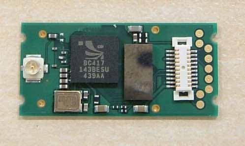
Click to zoom
Application Details
- Equipment Class
- DSS - Part 15 Spread Spectrum Transmitter
- Date of Grant
- Sep 18, 2005
- Application Purpose
- Original Equipment
- Date of Application
- Sep 18, 2005
- Equipment Note
- Laptop computer with GSM, WLAN and BT radios
- Frequency Range
- 2402.00000000 - 2480.00000000
- Company
- Sony Group Corporation
- Country
- Japan
Documents & Files
Document Text
Text extracted from the exhibit documents filed with the FCC. Open a document above to read the original.
Users Manual
Personal Computer VGN-TX600 Series SmartWi Connection Utility Guide VAIO® Computer Wireless Information 2 Table of Contents About your Computer........................................... 3 Contents .................................................................................... 3 About Wireless Connectivity .................................................... 4 About the SIM Card .................................................................. 4 About Wireless Connection Utility ...................... 9 Starting SmartWi Connection Utility........................................ 9 About the Wireless Switching Window ............ 12 Using the Wireless Switching Window .................................. 12 Using SmartWi Connection Utility .................... 13 Using the Cingular WWAN connection ................................. 13 Using the Wireless LAN connection ...................................... 15 Using the Bluetooth® connection ........................................... 20 General Functional Information ........................ 22 FAQ and Troubleshooting ................................. 23 Notice to Users ................................................... 33 About your Computer 3 About your Computer Thank you for purchasing a VAIO® VGN-TX600 Series computer! Your new machine combines state-of-the-art hardware and software to bring you unparalleled wireless connectivity. Contents These hardware components are included. * A Cingular SIM card is preinstalled in your computer. Carton Contents Computer* Power cord Battery AC adapter VAIO® Computer Wireless Information 4 About Wireless Connectivity With built-in Wireless WAN capabilities, your computer is equipped to connect wirelessly to your e-mail, the Internet, and any intranet networks with which you may be associated. To begin making use of wireless connectivity, you will need to insert a provided Subscriber Identity Module (SIM) card into the computer before turning on your computer. About the Cingular SIM Card The SIM card, provided by Cingular Wireless, is a small printed circuit board that stores data identifying the user to the network service provider. It must be inserted into the computer for you to make use of the wireless services. Inserting the Cingular SIM card The Cingular SIM card should be preinstalled; you may follow these procedures to verify that the SIM card is indeed installed in the SIM card slot at the rear of your computer. ✍ Only the Cingular SIM card is supported. It is normally preinstalled in your computer. Do not touch the SIM card connectors. As a precaution, always make sure you have a firm hold of your computer before inserting or removing the SIM card. About the Cingular SIM Card 5 1Unless preinstalled, your SIM card is contained within a larger card, about the size of a credit card. Remove the smaller SIM card by pushing it out from the larger card. 2Next, orient your computer so you are facing its rear portion. 3Locate the SIM card slot in the back of the computer and with its printed circuit side facing down, gently insert the SIM card into the slot. Check the SIM card for directions on which way to orient the card into the slot. Cingular SIM Card ✍Before inserting the SIM card into the computer, make sure your computer is turned off and the battery is not attached. VAIO® Computer Wireless Information 6 If your computer came with a preinstalled Cingular SIM card, verify that the card is indeed in the SIM card slot. If a SIM card can not be found in the unit, there are two ways to obtain the card: 1Contact Sony’s VAIO PC support line (888)-476-6972 and request a free replacement SIM card. Please note that you must have the VAIO product model number and serial number to receive the replacement SIM from Sony. Subject to availability, the replacement SIM card will be shipped from Sony to you without charge. 2Go to the local Cingular store and ask for SIM card for local service. Additional cost would apply in this process. Inserting the SIM card SIM card (printed circuit side face down) Cut-off corner oriented left About the Cingular SIM Card 7 ✍To activate your Cingular account, call Sony customer support at 888-604-VAIO (8246). When calling customer support, you may be asked for the SIM# (IMSI #) and IMEI code. To determine these values, start the Cingular Connection Manager (CCM), open Tools, and click Network Info. Alternatively, you can check the the rear of your VAIO computer. The IMEI # and SIM # (ICCID) should be printed on the back of your computer. Removing the SIM Card To remove the SIM card, again orient your computer so you are facing its rear portion. Make sure the computer is turned off. 1Locate the SIM card slot. 2Gently push in the SIM card until you hear it click, then release the card allowing the SIM card to eject. After the SIM card ejects, gently pull the card out of the slot, away from the computer. Do not touch the SIM card connectors. As a precaution, make sure you have a firm hold of your computer before inserting or removing the SIM card. VAIO® Computer Wireless Information 8 Removing the SIM Card ✍Take care not to damage the card in any way, either by bending or putting undue pressure on the card. About SmartWi Connection Utility 9 About SmartWi Connection Utility The SmartWi Connection Utility functions largely as a switch manager between the various forms of wireless connectivity: Bluetooth®, WLAN, and WWAN using Cingular Wireless software. By clicking on each of the three wireless options, the SmartWi Connection Utility switches to the corresponding one. Starting SmartWi Connection Utility At initial statup, a pop-up prompt appears from the Task Tray. Selecting Yes on the prompt launches the SmartWi Connection Utility, and then you are prompted to activate your Cingular account. If you close the program, however, and later wish to restart it, do the following: SmartWi Connection Utility main screen VAIO® Computer Wireless Information 10 1First make sure your com…
Text truncated - open the document above for the full version.
External Photos
UGPZ6 Photo Top view Bottom view No shield cover
Internal Photos
UGPZ6 Photo Top view Bottom view No shield cover UGPZ6 Antenna LDA31 top view Bottom view CAN4313359 top view Bottom view C680 top view Bottom view
RF Exposure Info
SAR Test Report No.: SAR_1008_2005_FCC_850_1900_2450 Date of Report: 8/18/2005 Appendix A Plots Page 1 of 14 System / software: SARA2 / 2.3 VPM Input Power Drift: Date / Time: 8/8/2005 11:37:54 AM DUT Battery Model/No: Filename: temp.txt Probe Serial Number: 0123 Ambient Temperature: 22.0°C Liquid Simulant: 850 Device Under Test: Sony 4F1L Relative Permittivity: 56.12 Relative Humidity: 50% Conductivity: 0.982 Phantom S/No: HeadBox_new_spout.c sv Liquid Temperature: 22.0°C Phantom Rotation: 0° Max SAR Y-axis Location: -13.00 mm DUT Position: lap Max SAR Z-axis Location: -173.90 mm Antenna Configuration: vertical Max E Field: 9.15 V/m Test Frequency: 836.6MHz SAR 1g: 0.071 W/kg Air Factors: 346 / 318 / 386 SAR 10g: 0.051 W/kg Conversion Factors: .522 / .522 / .522 SAR Start: 0.037 W/kg Type of Modulation: SAR End: 0.037 W/kg Modn. Duty Cycle: SAR Drift during Scan: 0.01 dB Diode Compression Factors (V*200): 10 / 11.7 / 7.7 Probe battery last changed: 7/25/05 Input Power Level: max Extrapolation: poly4 SAR Test Report No.: SAR_1008_2005_FCC_850_1900_2450 Date of Report: 8/18/2005 Appendix A Plots Page 2 of 14 System / software: SARA2 / 2.3 VPM Input Power Drift: Date / Time: 8/8/2005 12:12:07 PM DUT Battery Model/No: Filename: 190vert_3d.txt Probe Serial Number: 0123 Ambient Temperature: 22.0°C Liquid Simulant: 850 Device Under Test: Sony 4F1L Relative Permittivity: 56.12 Relative Humidity: 50% Conductivity: 0.982 Phantom S/No: HeadBox_new_spout.c sv Liquid Temperature: 22.0°C Phantom Rotation: 0° Max SAR Y-axis Location: -16.00 mm DUT Position: lap Max SAR Z-axis Location: -155.90 mm Antenna Configuration: horizontal Max E Field: 11.41 V/m Test Frequency: 836.6MHz SAR 1g: 0.115 W/kg Air Factors: 346 / 318 / 386 SAR 10g: 0.080 W/kg Conversion Factors: .522 / .522 / .522 SAR Start: 0.064 W/kg Type of Modulation: SAR End: 0.064 W/kg Modn. Duty Cycle: SAR Drift during Scan: 0.00 dB Diode Compression Factors (V*200): 10 / 11.7 / 7.7 Probe battery last changed: 7/25/05 Input Power Level: max Extrapolation: poly4 SAR Test Report No.: SAR_1008_2005_FCC_850_1900_2450 Date of Report: 8/18/2005 Appendix A Plots Page 3 of 14 System / software: SARA2 / 2.3 VPM Input Power Drift: Date / Time: 8/8/2005 12:47:30 PM DUT Battery Model/No: Filename: 190horz_3d.txt Probe Serial Number: 0123 Ambient Temperature: 22.0°C Liquid Simulant: 850 Device Under Test: Sony 4F1L Relative Permittivity: 56.12 Relative Humidity: 50% Conductivity: 0.982 Phantom S/No: HeadBox_new_spout.c sv Liquid Temperature: 22.0°C Phantom Rotation: 0° Max SAR Y-axis Location: -27.00 mm DUT Position: lap Max SAR Z-axis Location: -177.50 mm Antenna Configuration: detached Max E Field: 3.77 V/m Test Frequency: 836.6MHz SAR 1g: 0.011 W/kg Air Factors: 346 / 318 / 386 SAR 10g: 0.007 W/kg Conversion Factors: .522 / .522 / .522 SAR Start: 0.005 W/kg Type of Modulation: SAR End: 0.005 W/kg Modn. Duty Cycle: SAR Drift during Scan: 0.01 dB Diode Compression Factors (V*200): 10 / 11.7 / 7.7 Probe battery last changed: 7/25/05 Input Power Level: max Extrapolation: poly4 SAR Test Report No.: SAR_1008_2005_FCC_850_1900_2450 Date of Report: 8/18/2005 Appendix A Plots Page 4 of 14 System / software: SARA2 / 2.3 VPM Input Power Drift: Date / Time: 8/8/2005 1:24:24 PM DUT Battery Model/No: Filename: temp.txt Probe Serial Number: 0123 Ambient Temperature: 22.0°C Liquid Simulant: 850 Device Under Test: Sony 4F1L Relative Permittivity: 56.55 Relative Humidity: 50% Conductivity: 0.979 Phantom S/No: HeadBox_new_spout.c sv Liquid Temperature: 22.0°C Phantom Rotation: 0° Max SAR Y-axis Location: -18.00 mm DUT Position: lap Max SAR Z-axis Location: -154.10 mm Antenna Configuration: horizontal Max E Field: 9.85 V/m Test Frequency: 824.2MHz SAR 1g: 0.084 W/kg Air Factors: 346 / 318 / 386 SAR 10g: 0.059 W/kg Conversion Factors: .522 / .522 / .522 SAR Start: 0.046 W/kg Type of Modulation: SAR End: 0.046 W/kg Modn. Duty Cycle: SAR Drift during Scan: 0.01 dB Diode Compression Factors (V*200): 10 / 11.7 / 7.7 Probe battery last changed: 7/25/05 Input Power Level: max Extrapolation: poly4 SAR Test Report No.: SAR_1008_2005_FCC_850_1900_2450 Date of Report: 8/18/2005 Appendix A Plots Page 5 of 14 System / software: SARA2 / 2.3 VPM Input Power Drift: Date / Time: 8/8/2005 2:03:02 PM DUT Battery Model/No: Filename: 128horz_3d.txt Probe Serial Number: 0123 Ambient Temperature: 22.0°C Liquid Simulant: 850 Device Under Test: Sony 4F1L Relative Permittivity: 55.87 Relative Humidity: 50% Conductivity: 0.987 Phantom S/No: HeadBox_new_spout.c sv Liquid Temperature: 22.0°C Phantom Rotation: 0° Max SAR Y-axis Location: -19.00 mm DUT Position: lap Max SAR Z-axis Location: -155.90 mm Antenna Configuration: horizontal Max E Field: 11.09 V/m Test Frequency: 848.8MHz SAR 1g: 0.109 W/kg Air Factors: 346 / 318 / 386 SAR 10g: 0.078 W/kg Conversion Factors: .522 / .522 / .522 SAR Start: 0.059 W/kg Type of Modulation: SAR End: 0.060 W/kg Modn. Duty Cycle: SAR Drift during Scan: 0.10 dB Diode Compression Factors (V*200): 10 / 11.7 / 7.7 Probe battery last changed: 7/25/05 Input Power Level: max Extrapolation: poly4 SAR Test Report No.: SAR_1008_2005_FCC_850_1900_2450 Date of Report: 8/18/2005 Appendix A Plots Page 6 of 14 System / software: SARA2 / 2.3 VPM Input Power Drift: Date / Time: 8/9/2005 7:55:01 AM DUT Battery Model/No: Filename: temp.txt Probe Serial Number: 0123 Ambient Temperature: 22.0°C Liquid Simulant: 1900 Device Under Test: Sony 4F1L Relative Permittivity: 53.17 Relative Humidity: 50% Conductivity: 1.575 Phantom S/No: HeadBox_new_spout.c sv Liquid Temperature: 22.0°C Phantom Rotation: 0° Max SAR Y-axis Location: -28.00 mm DUT Position: lap Max SAR Z-axis Location: -170.30 mm Antenna Configuration: vertical Max E Field: 6.61 V/m Test Frequency: 1880MHz SAR 1g: 0.055 W/kg Air Factors: 346 / 318 / 386 SAR 10g: 0.032 W/kg Conversion Factors: 0.666 / 0.666 / 0.666 SAR Start: 0.019 W/kg Type of Modulation: SAR End: 0.019 W/kg Modn. Duty Cycle: SAR Drift during Scan: 0.00 dB Diode Com…
Text truncated - open the document above for the full version.
RF Exposure Info
SAR Test Report No: SAR_1008_2005_FCC_850_1900_2450 Date of Report: 8/18/2005 Appendix C Miscellaneous Page 1 of 11 1 Tissue Parameters 850MHz Head liquid: Recipe: The following recipe is provided in percentage by weight. 49.46% distilled water 49.46% DGBE 1.0% salt 0.1% bactericide SAR measurements were made within 24 hours of the measurement of liquid parameters. Freq. Rel. Condy Date (MHz) Perm. (S/m) 8/8/05 900 41.21 0.976 850MHz Body Liquid: Recipe: The following recipe is provided in percentage by weight. 49.8% distilled water 40.6% DGBE 8.9% salt 0.6% HEC 0.1% bactericide SAR measurements were made within 24 hours of the measurement of liquid parameters. Freq. Rel. Condy Date (MHz) Perm. (S/m) 8/8/05 824.2 56.55 0.979 8/8/05 836.6 56.12 0.982 8/8/05 848.8 55.87 0.987 SAR Test Report No: SAR_1008_2005_FCC_850_1900_2450 Date of Report: 8/18/2005 Appendix C Miscellaneous Page 2 of 11 2 1900MHz Head liquid: Recipe: The following recipe is provided in percentage by weight. 54.9% distilled water 44.92% DGBE 0.18% salt 0.1% bactericide SAR measurements were made within 24 hours of the measurement of liquid parameters. Freq. Rel. Condy Date (MHz) Perm. (S/m) 8/9/05 1900 38.41 1.415 1900MHz Body Liquid: Recipe: The following recipe is provided in percentage by weight. 69.17% distilled water 30.29% DGBE 0.44% salt 0.1% bactericide SAR measurements were made within 24 hours of the measurement of liquid parameters. Freq. Rel. Condy Date (MHz) Perm. (S/m) 8/9/05 1850.2 53.32 1.562 8/9/05 1880 53.17 1.575 8/9/05 1909.8 52.96 1.579 2450MHz Head liquid: Recipe: 53.74% distilled water 22.59% DGBE 22.59% triton X-100 0.98% salt 0.1% bactericide Di-electric constants measured on 8/10/2005. SAR measurements were made within 24 hours of the measurement of liquid parameters. SAR Test Report No: SAR_1008_2005_FCC_850_1900_2450 Date of Report: 8/18/2005 Appendix C Miscellaneous Page 3 of 11 3 Freq. Rel. Condy (MHz) Perm. (S/m) 2450 40.57 1.82 2450MHz Body Liquid: Recipe: 73.3% distilled water 12.88% DGBE 12.88% triton X-100 0.84% salt 0.1% bactericide Di-electric constants measured on 8/10/2005. SAR measurements were made within 24 hours of the measurement of liquid parameters. Freq. Rel. Condy (MHz) Perm. (S/m) 2402 50.97 1.863 2412 51.06 1.863 2437 51.09 1.912 2462 50.92 1.941 Environment: 8/8/2005 to 8/11/2005 Temperature: 22.0 °C ± 2°C Humidity: 45% _ 55 % SAR Test Report No: SAR_1008_2005_FCC_850_1900_2450 Date of Report: 8/18/2005 Appendix C Miscellaneous Page 4 of 11 4 Test Equipment Test Equipment Model Serial Instrument description Supplier / Manufacturer Model Serial No. Calibration (date) Calibration Due (date) Bench top Robot Mitsubishi supplied by IndexSAR RV-E2 EA1030108 N/A N/A SAM Phantom Upright shell phantom made by Antennessa digitized and mounted by IndexSAR SAM 03FT26 04/03 N/A Flat Phantom IndexSAR HeadBox_Spou t N/A N/A N/A Software IndexSAR SARA2 v0.420 N/A N/A N/A 900 MHz Head Tissue Simulant Cetecom Inc. 900 Head N/A 8/8/2005 N/A 850 MHz Body Tissue Simulant Cetecom Inc. 850 Body N/A 8/8/2005 N/A 1900 MHz Head Tissue Simulant Cetecom Inc. 1900 Head N/A 8/9/2005 N/A 1900 MHz Body Tissue Simulant Cetecom Inc. 1900 Body N/A 8/9/2005 N/A 2450 MHz Head Tissue Simulant Cetecom Inc. 2450 Head N/A 8/10/2005 N/A 2450 MHz body Tissue Simulant Cetecom Inc. 2450 Body N/A 8/10/2005 N/A 900 MHz Dipole IndexSAR – IEEE 1528 design IXD-900 0016 07/20/2005 07/20/2006 1900 MHz Dipole IndexSAR – IEEE 1528 design IXD-190 0016 07/20/2005 07/20/2006 2450 MHz Dipole IndexSAR – IEEE 1528 design IXD-245 0016 07/20/2005 07/20/2006 Directional coupler Werlatone C6529 11249 N/A N/A RF Amplifier Vectawave VTL5400 N/A N/A N/A SAR Probe IndexSAR IXP-050 S/N 0123 10/07/2004 10/07/2005 Probe amplifier IndexSAR IXA-010 S/N 043 N/A N/A Thermometer Control Company 4039 20410549 11/20/2001 11/20/2005 Dielectric Measurement Kit IndexSAR Di-Line N/A N/A N/A SAR Test Report No: SAR_1008_2005_FCC_850_1900_2450 Date of Report: 8/18/2005 Appendix C Miscellaneous Page 5 of 11 5 Equipment Calibration/Performance Documents: Validation Dipoles Performance Measurements: Pages 6 to 11 Please Note: (The following pages of Appendix C show calibration documents. These calibration documents are inserted into this appendix. The header information with page numbering scheme is a part of this report and is included on all pages of the report and appendixes. This header is used to track all of the contents of this report.) SAR Test Report No: SAR_1008_2005_FCC_850_1900_2450 Date of Report: 8/18/2005 Appendix C Miscellaneous Page 6 of 11 6 Report No. SN0016_090-180-190-245 July 1 st 2002 Revised 7/20/2005 INDEXSAR Validation Dipoles Type IXD-090, IXD-180, IXD-190 & IXD-245 Performance measurements S/N: 090-0016 S/N: 180-0016 S/N: 245-0016 S/N: 190-0016 MI Manning Indexsar, Oakfield House, Cudworth Lane, Newdigate, Surrey RH5 5DR. UK. Tel: +44 (0) 1306 631233 Fax: +44 (0) 1306 631834 e-mail: [email protected] SAR Test Report No: SAR_1008_2005_FCC_850_1900_2450 Date of Report: 8/18/2005 Appendix C Miscellaneous Page 7 of 11 7 1. Measurement Conditions Measurements were performed using a box-shaped phantom made of PMMA with dimensions designed to meet the accuracy criteria for reasonably-sized phantoms that do not have liquid capacities substantially in excess of the volume of liquid required to fill the Indexsar upright SAM phantoms used for SAR testing of handsets against the ear. An HP 8753B vector network analyser was used for the return loss measurements. The dipole was placed in a special holder made of low-permittivity, low-loss materials. This holder enables the dipole to be positioned accurately in the centre of the base of the Indexsar box-phantom used for flat-surface testing and validation checks. The validation dipoles are supplied with special spacers made form a low-permittivity, low-loss foam material. These spacers are fitted to the dipole arms to ensure that, when the dipole is offered up to the phantom surface, the …
Text truncated - open the document above for the full version.
RF Exposure Info
TTI-P-G 081/94-A0 ACCREDITED ACCORDING TO ISO/IEC 17025 Bluetooth Qualification Test Facility (BQTF) FCC listed # 101450 IC recognized # 3925 CETECOM Inc. 411 Dixon Landing Road Milpitas, CA 95035 U.S.A. Phone: + 1 (408) 586 6200 Fax: + 1 (408) 586 6299 E-mail: [email protected] http://www.cetecom.com CETECOM Inc. is a Delaware Corporation with Corporation number: 2113686 Board of Directors: Dr. Harald Ansorge, Dr. Klaus Matkey, Hans Peter May V.2.16M-2002-03-12 \\stupendousman\rootappsdata\emc\projects_emc\sony\1008_tx_platform\sar\report\850_1900_2450\sar_1008 _2005_fcc_850_1900_2450rev2.doc © Copyright by CETECOM SAR Test Report No.: SAR_1008_2005_FCC_850_1900_2450 for the SONY Corporation Personal Computer Model Number: VGC-TX FCC ID: AK8PCG4F1L IC-ID: 409B-PCG4F1L Date of Report: 8/18/2005 Date of issue: 8/18/2005 Report Copy No.: 01 SAR Test Report No. SAR_1008_2005_FCC_850_1900_2450 Date of Report: 8/18/2005 Page 2 of 27 This report shall not be reproduced except in full without the written approval of: CETECOM Inc. SAR 411 Dixon Landing Road Milpitas, CA 95035 U.S.A. Contents 1 ASSESSMENT ...................................................................................................................4 2 ADMINISTRATIVE DATA...................................................................................................5 2.1 Identification of the Testing Laboratory Issuing the SAR Assessment Report ...............5 2.2 Identification of the Client...........................................................................................5 2.3 Identification of the Manufacturer...............................................................................5 3 EQUIPMENT UNDER INVESTIGATION (EUI)...................................................................6 3.1 Identification of the Equipment under Investigation ...................................................6 4 SUBJECT OF INVESTIGATION ........................................................................................7 4.1 The IEEE Standard C95.1 and the FCC Exposure Criteria .......................................7 4.2 Distinction Between Exposed Population, Duration of Exposure and Frequencies...7 4.3 Distinction between Maximum Permissible Exposure and SAR Limits......................8 4.4 SAR Limit ...................................................................................................................8 5 THE FCC MEASUREMENT PROCEDURE .......................................................................9 5.1 General Requirements...............................................................................................9 5.2 Test Positions ..........................................................................................................10 5.3 Body-worn and Other Configurations.......................................................................10 5.4 Procedure for assessing the peak spatial-average SAR .........................................10 5.5 Determination of the largest peak spatial-average SAR ..........................................12 6 THE MEASUREMENT SYSTEM ......................................................................................14 6.1 Robot system specification ......................................................................................14 6.2 Probe and amplifier specification .............................................................................15 6.3 Phantoms.................................................................................................................15 6.4 SAR measurement procedure .................................................................................16 6.5 SARA2 Interpolation and Extrapolation schemes ....................................................16 6.6 Interpolation of 2D area scan...................................................................................17 6.7 Extrapolation of 3D scan..........................................................................................17 6.8 Interpolation of 3D scan and volume averaging.......................................................17 SAR Test Report No. SAR_1008_2005_FCC_850_1900_2450 Date of Report: 8/18/2005 Page 3 of 27 This report shall not be reproduced except in full without the written approval of: CETECOM Inc. SAR 411 Dixon Landing Road Milpitas, CA 95035 U.S.A. 7 UNCERTAINTY ASSESSMENT.......................................................................................19 7.1 Table of Measurement Uncertainty Values of SAR Evaluations..............................20 7.2 Table of Measurement Uncertainty Values for SAR System Verification ................20 8 TEST RESULTS SUMMARY............................................................................................22 8.1 Radiated Output Power............................................................................................22 8.2 Test Positions and Configurations ...........................................................................22 8.3 850 MHz band SAR Results for VGC-TX ................................................................23 8.4 1900 MHz band SAR Results for VGC-TX ..............................................................23 8.5 Validation Check Results .........................................................................................25 9 REFERENCES..................................................................................................................27 SAR Test Report No. SAR_1008_2005_FCC_850_1900_2450 Date of Report: 8/18/2005 Page 4 of 27 This report shall not be reproduced except in full without the written approval of: CETECOM Inc. SAR 411 Dixon Landing Road Milpitas, CA 95035 U.S.A. 1 Assessment The SONY Corporation VGC-TX Personal Computer, FCC ID: AK8PCG4F1L, is in compliance with the limits for general population uncontrolled exposure specified in FCC 2.1093. The device was tested according to m…
Text truncated - open the document above for the full version.
Test Report
TTI-P-G 081/94-A0 Accredited according to ISO/IEC 17025 Bluetooth Qualification Test Facility (BQTF) FCC listed # 101450 IC recognized # 3925 CETECOM Inc. 411 Dixon Landing Road Milpitas, CA 95035 U.S.A. Phone: + 1 (408) 586 6200 Fax: + 1 (408) 586 6299 E-mail: [email protected] http://www.cetecom.com CETECOM Inc. is a Delaware Corporation with Corporation number: 2113686 Board of Directors: Dr. Harald Ansorge, Dr. Klaus Matkey, Hans Peter May V1.1 2003-03-01 The BLUETOOTH trademarks are owned by Bluetooth SIG, Inc., U.S.A. and licensed to CETECOM Inc. © Copyright by CETECOM FCC Test Report FCC Part 15.247 for FHSS systems/ CANADA RSS-210 FOR: PERSONAL COMPUTER MODEL #: PCG-4F1L SONY CORPORATION 6-7-35, KITASHINAGAWA, SHINAGAWA-KU TOKYO 141-001 FCC ID: AK8PCG4F1L IC ID: 409B-PCG4F1L TEST REPORT #: EMC_1008_2005_BLUETOOTH DATE: AUGUST 17, 2005 Test Report #: EMC_1008_2005_BLUETOOTH Date of Report: 2005-08-17 Page 2 of 47 TABLE OF CONTENTS 1 Assessment_____________________________________________________________________ 3 2 Administrative Data _____________________________________________________________ 4 2.1 Identification of the Testing Laboratory Issuing the EMC Test Report _____________________ 4 2.2 Identification of the Client __________________________________________________________ 4 2.3 Identification of the Manufacturer ___________________________________________________ 4 3 Equipment under Test (EUT) ______________________________________________________ 5 3.1 Identification of the Equipment under Test____________________________________________ 5 4 Subject Of Investigation __________________________________________________________ 6 5 Measurements __________________________________________________________________ 7 5.1 MAXIMUM PEAK OUTPUT POWER § 15.247 (RADIATED) ___________________________ 7 5.1.1 LIMIT SUB CLAUSE § 15.247 (b) (1) (2) (3) (4)_______________________________________________ 7 5.1.2 EIRP: _________________________________________________________________________________ 7 5.2 RESTRICTED BAND EDGE COMPLIANCE RADIATED §15.247/15.205 ________________ 11 5.2.1 LIMITS _______________________________________________________________________________ 11 5.2.2 RESULTS (2402MHz) ___________________________________________________________________ 12 5.2.3 RESULTS (2480MHz) ___________________________________________________________________ 14 5.3 TRANSMITTER SPURIOUS EMISSIONS RADIATED § 15.247/15.205/15.209 ____________ 16 5.3.1 LIMITS _______________________________________________________________________________ 16 5.3.2 RESULTS _____________________________________________________________________________ 17 5.4 RECEIVER SPURIOUS RADIATION § 15.209/RSS210 ________________________________ 26 5.4.1 LIMITS _______________________________________________________________________________ 26 5.4.2 RESULTS _____________________________________________________________________________ 27 5.5 CO-LOCATION _________________________________________________________________ 32 5.5.1 RESULTS (WLAN AND BLUETOOTH)____________________________________________________ 33 5.5.2 RESULTS (PCS AND BLUETOOTH) ______________________________________________________ 38 5.6 AC POWER LINE CONDUCTED EMISSIONS § 15.107/207 ___________________________ 43 5.6.1 LIMITS _______________________________________________________________________________ 43 5.6.2 RESULTS (WLAN AND BLUETOOTH)____________________________________________________ 44 5.6.3 RESULTS (PCS AND BLUETOOTH) ______________________________________________________ 45 5.7 TEST EQUIPMENT AND ANCILLARIES USED FOR TESTS _________________________ 46 5.8 BLOCK DIAGRAMS _____________________________________________________________ 47 Test Report #: EMC_1008_2005_BLUETOOTH Date of Report: 2005-08-17 Page 3 of 47 1 Assessment The following is in compliance with the applicable criteria specified in FCC rules Part 15.247 of the Code of Federal Regulations and in compliance with the applicable criteria specified in Industry Canada rules RSS210. Company Description Model # SONY CORPORATION PERSONAL COMPUTER PCG-4F1L 2005-08-17 2005-08-17 Neelesh Raj Lothar Schmidt Project Leader Test Lab Manager The test results of this test report relate exclusively to the test item specified in Identification of the Equipment under Test. The CETECOM Inc. USA does not assume responsibility for any conclusions and generalizations drawn from the test results with regard to other specimens or samples of the type of the equipment represented by the test item. The test report may only be reproduced or published in full. Reproduction or publication of extracts from the report requires the prior written approval of the CETECOM Inc USA. Test Report #: EMC_1008_2005_BLUETOOTH Date of Report: 2005-08-17 Page 4 of 47 2 Administrative Data 2.1 Identification of the Testing Laboratory Issuing the EMC Test Report Company Name: CETECOM Inc. Department: EMC Address: 411 Dixon Landing Road Milpitas, CA 95035 U.S.A. Telephone: +1 (408) 586 6200 Fax: +1 (408) 586 6299 Responsible Test Lab Manager: Lothar Schmidt Responsible Project Leader: Neelesh Raj Date of test: 2005-08-05 to 2005-08-11 2.2 Identification of the Client Applicant’s Name: SONY Corporation Street Address: 6-7-35, Kitashinagawa, Shinagawa-ku, City/Zip Code Tokyo 141-0001 Country Japan Contact Person: Takumi Ozawa Phone No. 81-3-5795-8716 Fax: 81-3-5795-8981 e-mail: [email protected] 2.3 Identification of the Manufacturer Manufacturer’s Name: Sony EMCS Corporation Manufacturers Address: 5432 Toyoshima, Toyoshima-machi, Minamiiazumi- gun, City/Zip Code Nagano 399-8282, Country Japan Test Report #: EMC_1008_2005_BLUETOOTH Date of Report: 2005-08-17 Page 5 of 47 3 Equipment under Test (EUT) 3.1 Identification of the Equipmen…
Text truncated - open the document above for the full version.
Contact Information
Applicant
Kazuyuki Hori(Chief EMC/RF Compliance Specialist)
Test Firm
Cetecom Inc.Lothar Schmidt
Technical Specifications
| # | Rule Parts | Frequency Range | Power Output |
|---|---|---|---|
| 1 | 15C | 2.40 GHz - 2.48 GHz | 1.24 mW |
Other Applications from Sony Group Corporation
AK8WW81782
Aug 21, 2026Radio Equipment
Equipment Class
DSS - Part 15 Spread Spectrum TransmitterAK8CFIZCP2
Aug 03, 2026Wireless Controller
Equipment Class
DSS - Part 15 Spread Spectrum TransmitterAK8OEV321MUH
Apr 14, 2026LCD Monitor
Equipment Class
JAD - Part 15 Class A Digital DeviceAK8OEV431MUH
Apr 14, 2026LCD Monitor
Equipment Class
JAD - Part 15 Class A Digital DeviceAK8OEV271MUH
Apr 14, 2026LCD Monitor
Equipment Class
JAD - Part 15 Class A Digital Device