AK8PCG4H2LPersonal Computer
Sony Group Corporation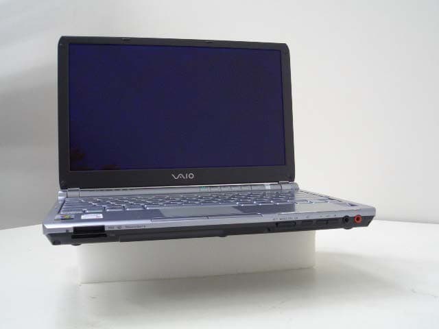
Click to zoom
Application Details
- Equipment Class
- DTS - Digital Transmission System
- Date of Grant
- Jun 07, 2006
- Application Purpose
- Original Equipment
- Date of Application
- Apr 24, 2006
- Equipment Note
- Personal Computer
- Frequency Range
- 5745.00000000 - 5825.00000000
- Company
- Sony Group Corporation
- Country
- Japan
Documents & Files
Document Text
Text extracted from the exhibit documents filed with the FCC. Open a document above to read the original.
Users Manual
N User Guide Personal Computer VGN-TX800 Series 2 nN Contents Before Use .........................................................................................................................................................................6 Documentation .............................................................................................................................................................6 Ergonomic Considerations ...........................................................................................................................................8 Getting Started .................................................................................................................................................................10 Locating Controls and Ports.......................................................................................................................................11 About the Indicator Lights ..........................................................................................................................................18 Connecting a Power Source ......................................................................................................................................20 Using the Battery Pack ..............................................................................................................................................21 Shutting Down Your Computer Safely .......................................................................................................................25 Using Your VAIO Computer .............................................................................................................................................26 Using the Keyboard ...................................................................................................................................................27 Using the Touch Pad .................................................................................................................................................29 Using Special-function Buttons ..................................................................................................................................30 Using the Optical Disc Drive ......................................................................................................................................32 Using PC Cards .........................................................................................................................................................42 Using the Memory Stick Media ..................................................................................................................................45 Using Other Memory Cards .......................................................................................................................................49 Using the Internet.......................................................................................................................................................51 Using Wireless LAN (WLAN) .....................................................................................................................................52 Using the Bluetooth Functionality ..............................................................................................................................61 3 nN Using Peripheral Devices .................................................................................................................................................66 Connecting a Port Replicator .....................................................................................................................................67 Connecting External Speakers ..................................................................................................................................71 Connecting an External Display .................................................................................................................................72 Selecting Display Modes............................................................................................................................................75 Using the Multiple Monitors Function .........................................................................................................................76 Connecting an External Microphone ..........................................................................................................................78 Connecting a Universal Serial Bus (USB) Device......................................................................................................79 Connecting a Printer ..................................................................................................................................................82 Connecting an i.LINK Device .....................................................................................................................................83 Connecting to a Network (LAN) .................................................................................................................................85 Customizing Your VAIO Computer ..................................................................................................................................86 Setting the Password .................................................................................................................................................87 Using Fingerprint Authentication ................................................................................................................................96 Using Trusted Platform Module (TPM).....................................................................................................................113 Setting Up Your Computer with VAIO Central ..........................................................................................…
Text truncated - open the document above for the full version.
Users Manual
Por favor lea detalladamente este manual de instrucciones antes de conectar y operar este equipo. Recuerde que un mal uso de su aparato podría anular la garantía. IMPORTANTE! ! Personal Computer / Computadora Personal VGN-TX800 Series Safety Information / Información de Seguridad 2 For customers in USA and Canada Pour les utilisateurs aux Etats-Unis et au Canada Owner’s Record The model number and serial number are located on the back panel of your Sony VAIO® computer. Record the model and serial number in the space provided here, and keep in a secure location. Refer to the model and serial numbers when you call your Sony Service Center. Notice © 2006 Sony Electronics Inc. Reproduction in whole or in part without written permission is prohibited. All rights reserved. This manual and the software described herein, in whole or in part, may not be reproduced, translated, or reduced to any machine-readable form without prior written approval. SONY ELECTRONICS INC. PROVIDES NO WARRANTY WITH REGARD TO THIS MANUAL, THE SOFTWARE, OR OTHER INFORMATION CONTAINED HEREIN AND HEREBY EXPRESSLY DISCLAIMS ANY IMPLIED WARRANTIES OF MERCHANTABILITY OR FITNESS FOR ANY PARTICULAR PURPOSE WITH REGARD TO THIS MANUAL, THE SOFTWARE, OR SUCH OTHER INFORMATION. IN NO EVENT SHALL SONY ELECTRONICS INC. BE LIABLE FOR ANY INCIDENTAL, CONSEQUENTIAL, OR SPECIAL DAMAGES, WHETHER BASED ON TORT, CONTRACT, OR OTHERWISE, ARISING OUT OF OR IN CONNECTION WITH THIS MANUAL, THE SOFTWARE, OR OTHER INFORMATION CONTAINED HEREIN OR THE USE THEREOF. SONY CANNOT WARRANT THAT THE FUNCTIONS DESCRIBED IN THIS GUIDE WILL BE UNINTERRUPTED OR ERROR-FREE. SONY ALSO ASSUMES NO RESPONSIBILITY, AND SHALL NOT BE LIABLE FOR ANY DAMAGES TO, OR VIRUSES THAT MAY INFECT, YOUR COMPUTER EQUIPMENT, OR OTHER PROPERTY ON ACCOUNT OF YOUR ACCESS TO, USE OF, OR BROWSING IN ANY DESCRIBED WEB SITE, OR YOUR DOWNLOADING OF ANY MATERIALS, DATA, TEXT, IMAGES, VIDEO, OR AUDIO FROM ANY DESCRIBED WEB SITE. WEB SITE INFORMATION IS OBTAINED FROM VARIOUS SOURCES AND MAY BE INACCURATE. COPIES OF COPYRIGHTED INFORMATION MAY ONLY BE MADE FOR LEGALLY PERMISSIBLE PURPOSES. Sony Electronics Inc. reserves the right to make any modification to this manual or the information contained herein at any time without notice. The software described herein is governed by the terms of a separate user license agreement. This product contains software owned by Sony and licensed by third parties. Use of such software is subject to the terms and conditions of license agreements enclosed with this product. Some of the software may not be transported or used outside the United States. Software specifications are subject to change without notice and may not necessarily be identical to current retail versions. Certain product(s) included with this computer may include features such as copy protection and content management technology. USE OF THE SOFTWARE PRODUCT(S) REQUIRES AGREEMENT TO APPLICABLE END USER AGREEMENTS AND FULL COMPLIANCE WITH APPLICABLE PRODUCT Model Number: Serial Number: 3 ACTIVATION PROCEDURES. Product activation procedures and privacy policies will be detailed during initial launch of the software product(s), or upon certain reinstallations of the software product(s), or reconfigurations of the computer, and may be completed by Internet or telephone (toll charges may apply). Updates and additions to software may require an additional charge. Subscriptions to online service providers may require a fee and credit card information. Financial services may require prior arrangements with participating financial institutions. Important information for Canadian customers: Your new VAIO computer includes certain software versions or upgrades, and Internet services or offers that are available to U.S. customers only. Sony, VAIO, the VAIO logo, VAIO Digital Studio, VAIO Media, VAIO Media Music Server, VAIO Media Photo Server, VAIO Media Video Server, Click to DVD, CLIÉ, DVgate Plus, Handycam, MagicGate, Memory Stick, the Memory Stick logo, OpenMG, MICROMV, SonicStage, ImageStation, ATRAC3, and i.LINK are trademarks or registered trademarks of Sony. Intel and Pentium are trademarks or registered trademarks of Intel Corporation. Microsoft, Windows, and the Windows logo are trademarks or registered trademarks of Microsoft Corporation. PS/2 is a registered trademark of IBM Corporation. All other trademarks are trademarks or registered trademarks of their respective owners. The International ENERGY STAR® Office Equipment Program is an international program that promotes energy saving through the use of computers and other office equipment. The program backs the development and dissemination of products with functions that effectively reduce energy consumption. It is an open system in which business proprietors can participate voluntarily. The targeted products are office equipment such as computers, displays, printers, facsimiles and copiers. Their standards and logos are uniform among participating nations. ENERGY STAR is a U.S. registered trademark of the Environmental Protection Agency. As an ENERGY STAR® Partner, Sony Corporation has determined that this product meets the ENERGY STAR® guidelines for energy efficiency. 4 Reverse engineering or disassembly is prohibited. i.LINK is a trademark of Sony used only to designate that a product contains an IEEE 1394 connection. The i.LINK connection may vary, depending on the software applications, operating system, and compatible i.LINK devices. All products with an i.LINK connection may not communicate with each other. Please refer to the documentation that came with your compatible i.LINK device for information on operating conditions and proper connection. Before connecting compatible i.LINK PC peripherals to your system, such as a CD-RW or hard disk drive, confirm their operating system compatibility and required operating conditions. All other trademarks are trademarks of their respective owners. End User / Product Activation Requirements…
Text truncated - open the document above for the full version.
External Photos
External Photo Sony Corporation Personal Computer (Model: PCG-4H2L) FCC ID: AK8PCG4H2L Back (Closed) Back (Open) External Photo Sony Corporation Personal Computer (Model: PCG-4H2L) FCC ID: AK8PCG4H2L Front (Closed) Front (Open) External Photo Sony Corporation Personal Computer (Model: PCG-4H2L) FCC ID: AK8PCG4H2L Side 1 (Closed) Side 2 (Closed)
Internal Photos
Internal Photo Sony Corporation Personal Computer (Model: PCG-4H2L) FCC ID: AK8PCG4H2L WLAN module Internal View 1 (WLAN module location) Bluetooth module Internal View 2 (Bluetooth module location) Internal Photo Sony Corporation Personal Computer (Model: PCG-4H2L) FCC ID: AK8PCG4H2L WLAN module (with cover) WLAN module (Cover off) Internal Photo Sony Corporation Personal Computer (Model: PCG-4H2L) FCC ID: AK8PCG4H2L WLAN module Bottom Internal Photo Sony Corporation Personal Computer (Model: PCG-4H2L) FCC ID: AK8PCG4H2L Bluetooth Module Internal Photo Sony Corporation Personal Computer (Model: PCG-4H2L) FCC ID: AK8PCG4H2L AUX ANTENNA MAIN ANTENNA Front Panel (Cover off)
RF Exposure Info
Test report No. : 26HE0320-HO-D-1 Page : 2 of 136 Issued date : April 24, 2006 Revised date : June 2, 2006 FCC ID : AK8PCG4H2L UL Apex Co., Ltd. Head Office EMC Lab. 4383-326 Asama-cho, Ise-shi, Mie-ken 516-0021 JAPAN Telephone: +81 596 24 8116 Facsimile: +81 596 24 8124 CONTENS Page SECTION 1 : Client information ........................................................................................................................................... 3 SECTION 2 : Equipment under test (E.U.T.) ....................................................................................................................... 4 2.2 Product description............................................................................................................................................. 4 SECTION 3 : Test standard information .............................................................................................................................. 6 3.1 Requirements for compliance testing defined by the FCC ................................................................................. 6 3.2 Exposure limit .................................................................................................................................................... 7 SECTION 4 : Test result ......................................................................................................................................................... 8 4.1 Result of Max. SAR value.................................................................................................................................. 8 4.2 Test Location...................................................................................................................................................... 8 SECTION 5 : Operation of E.U.T. during testing ................................................................................................................ 9 5.1 Operating modes ................................................................................................................................................ 9 5.2 Measurement procedure ..................................................................................................................................... 10 5.3 Test setup of EUT .............................................................................................................................................. 12 SECTION 6 : Test surrounding.............................................................................................................................................. 13 6.1 Measurement uncertainty ................................................................................................................................... 13 SECTION 7 : Confirmation before testing ............................................................................................................................ 14 7.1 Conducted power of Main Antenna Port ............................................................................................................ 14 7.2 Conducted power of Aux Antenna Port.............................................................................................................. 15 7.3 Conducted power of Bluetooth Antenna port ..................................................................................................... 16 SECTION 8 : Measurement results ....................................................................................................................................... 17 8.1 SAR measurement results..................................................................................................................................... 17 APPENDIX 1 : Photographs of test setup ........................................................................................................................... 22 1. Photograph of EUT............................................................................................................................................. 23 2. Antenna Location ............................................................................................................................................... 24 3. Photograph of Setup ........................................................................................................................................... 25 APPENDIX 2 : Test instruments.......................................................................................................................................... 39 Equipment & calibration information ..................................................................................................................... 40 1. Equipment used .................................................................................................................................................. 40 2. Dosimetry assessment setup ............................................................................................................................... 41 3. Configuration and peripherals ............................................................................................................................ 42 4. System components ............................................................................................................................................ 43 5. Test system specifications .................................................................................................................................. 45 6. Simulated Tissues Composition.......................................................................................................................... 46 7. Simulated Tissue Liquid Parameter confirmation............................................................................................... 46 8. System validation data.........................................................................................................................…
Text truncated - open the document above for the full version.
RF Exposure Info
Test report No. : 26HE0320-HO-D-1 Page : 76 of 136 Issued date : April 24, 2006 Revised date : June 2, 2006 FCC ID : AK8PCG4H2L UL Apex Co., Ltd. Head Office EMC Lab. 4383-326 Asama-cho, Ise-shi, Mie-ken 516-0021 JAPAN Telephone: +81 596 24 8116 Facsimile: +81 596 24 8124 13. Dosimetric E-Field Probe Calibration (EX3DV3,S/N: 3507) Test report No. : 26HE0320-HO-D-1 Page : 77 of 136 Issued date : April 24, 2006 Revised date : June 2, 2006 FCC ID : AK8PCG4H2L UL Apex Co., Ltd. Head Office EMC Lab. 4383-326 Asama-cho, Ise-shi, Mie-ken 516-0021 JAPAN Telephone: +81 596 24 8116 Facsimile: +81 596 24 8124 Test report No. : 26HE0320-HO-D-1 Page : 78 of 136 Issued date : April 24, 2006 Revised date : June 2, 2006 FCC ID : AK8PCG4H2L UL Apex Co., Ltd. Head Office EMC Lab. 4383-326 Asama-cho, Ise-shi, Mie-ken 516-0021 JAPAN Telephone: +81 596 24 8116 Facsimile: +81 596 24 8124 Test report No. : 26HE0320-HO-D-1 Page : 79 of 136 Issued date : April 24, 2006 Revised date : June 2, 2006 FCC ID : AK8PCG4H2L UL Apex Co., Ltd. Head Office EMC Lab. 4383-326 Asama-cho, Ise-shi, Mie-ken 516-0021 JAPAN Telephone: +81 596 24 8116 Facsimile: +81 596 24 8124 Test report No. : 26HE0320-HO-D-1 Page : 80 of 136 Issued date : April 24, 2006 Revised date : June 2, 2006 FCC ID : AK8PCG4H2L UL Apex Co., Ltd. Head Office EMC Lab. 4383-326 Asama-cho, Ise-shi, Mie-ken 516-0021 JAPAN Telephone: +81 596 24 8116 Facsimile: +81 596 24 8124 Test report No. : 26HE0320-HO-D-1 Page : 81 of 136 Issued date : April 24, 2006 Revised date : June 2, 2006 FCC ID : AK8PCG4H2L UL Apex Co., Ltd. Head Office EMC Lab. 4383-326 Asama-cho, Ise-shi, Mie-ken 516-0021 JAPAN Telephone: +81 596 24 8116 Facsimile: +81 596 24 8124 Test report No. : 26HE0320-HO-D-1 Page : 82 of 136 Issued date : April 24, 2006 Revised date : June 2, 2006 FCC ID : AK8PCG4H2L UL Apex Co., Ltd. Head Office EMC Lab. 4383-326 Asama-cho, Ise-shi, Mie-ken 516-0021 JAPAN Telephone: +81 596 24 8116 Facsimile: +81 596 24 8124 Test report No. : 26HE0320-HO-D-1 Page : 83 of 136 Issued date : April 24, 2006 Revised date : June 2, 2006 FCC ID : AK8PCG4H2L UL Apex Co., Ltd. Head Office EMC Lab. 4383-326 Asama-cho, Ise-shi, Mie-ken 516-0021 JAPAN Telephone: +81 596 24 8116 Facsimile: +81 596 24 8124 Test report No. : 26HE0320-HO-D-1 Page : 84 of 136 Issued date : April 24, 2006 Revised date : June 2, 2006 FCC ID : AK8PCG4H2L UL Apex Co., Ltd. Head Office EMC Lab. 4383-326 Asama-cho, Ise-shi, Mie-ken 516-0021 JAPAN Telephone: +81 596 24 8116 Facsimile: +81 596 24 8124 Test report No. : 26HE0320-HO-D-1 Page : 85 of 136 Issued date : April 24, 2006 Revised date : June 2, 2006 FCC ID : AK8PCG4H2L UL Apex Co., Ltd. Head Office EMC Lab. 4383-326 Asama-cho, Ise-shi, Mie-ken 516-0021 JAPAN Telephone: +81 596 24 8116 Facsimile: +81 596 24 8124 Test report No. : 26HE0320-HO-D-1 Page : 86 of 136 Issued date : April 24, 2006 Revised date : June 2, 2006 FCC ID : AK8PCG4H2L UL Apex Co., Ltd. Head Office EMC Lab. 4383-326 Asama-cho, Ise-shi, Mie-ken 516-0021 JAPAN Telephone: +81 596 24 8116 Facsimile: +81 596 24 8124 14. References [1]ANSI, ANSI/IEEE C95.1-1992: IEEE Standard for Safety Levels with Respect to Human Exposure to Radio Frequency Electromagnetic Fields, 3 kHz to 300 GHz, The Institute of Electrical and Electronics Engineers, Inc., New York, NY 10017, 1992. [2] Katja Pokovic, Thomas Schmid, and Niels Kuster, “Robust setup for precise calibration of E-field probes in tissue simulating liquids at mobile communications frequencies”, in ICECOM ‘97, Dubrovnik, October 15-17, 1997, pp. 120-124. [3] Katja Pokovic, Thomas Schmid, and Niels Kuster, “E-_field probe with improved isotropy in brain simulating liquids”, in Proceedings of the ELMAR, Zadar, Croatia, 23-25 June, 1996, pp.172-175. [4] W. Gander, Computermathematik, Birkhaeuser, Basel, 1992. [5] W. H. Press, S. A. Teukolsky,W. T. Vetterling, and B. P. Flannery, Numerical Recepies in C, The Art of Scientific Computing, Second Edition, Cambridge University Press, 1992. [6]SPEAG uncertainty document for DASY 4 System from SPEAG (Shimid & Partner Engineering AG). [7]SPEAG uncertainty document for "the 5-6GHz Extension" from SPEAG (Shimid & Partner Engineering AG). Test report No. : 26HE0320-HO-D-1 Page : 87 of 136 Issued date : April 24, 2006 Revised date : June 2, 2006 FCC ID : AK8PCG4H2L UL Apex Co., Ltd. Head Office EMC Lab. 4383-326 Asama-cho, Ise-shi, Mie-ken 516-0021 JAPAN Telephone: +81 596 24 8116 Facsimile: +81 596 24 8124 APPENDIX 3 : SAR Measurement data Test report No. : 26HE0320-HO-D-1 Page : 88 of 136 Issued date : April 24, 2006 Revised date : June 2, 2006 FCC ID : AK8PCG4H2L UL Apex Co., Ltd. Head Office EMC Lab. 4383-326 Asama-cho, Ise-shi, Mie-ken 516-0021 JAPAN Telephone: +81 596 24 8116 Facsimile: +81 596 24 8124 1. Evaluation procedure The evaluation was performed with the following procedure: Step 1: Measurement of the E-field at a fixed location above the ear point or central position of flat phantom was used as a reference value for assessing the power drop. Step 2: The SAR distribution at the exposed side of head or body position was measured at a distance of each device from the inner surface of the shell. The area covered the entire dimension of the antenna of EUT and the horizontal grid spacing was [20 mm x 20 mm] or [10mm x 10mm]. Based on these data, the area of the maximum absorption was determined by spline interpolation. Step 3: Around this point found in the Step 2 (area scan) , a volume of 25.8 mm x 25.8 mm x 21 mm was assessed by measuring 7 x 7 x 7 points. And for any secondary peaks found in the Step2 which are within 2dB of maximum peak and not with this Step3 (Zoom scan) is repeated. On the basis of this data set, the spatial peak SAR value was evaluated under the following procedure: (1). The data at the surface were extrapolated, since the center of the dipoles is 1mm away from the tip of the probe and the distance between the surface and the lowest measuring point is 1.3 mm. The extrapolation was b…
Text truncated - open the document above for the full version.
RF Exposure Info
Test report No. : 26HE0320-HO-E-1 Page : 2 of 107 Issued date : April 24, 2006 Revised date : June 2, 2006 FCC ID : AK8PCG4H2L UL Apex Co., Ltd. Head Office EMC Lab. 4383-326 Asama-cho, Ise-shi, Mie-ken 516-0021 JAPAN Telephone: +81 596 24 8116 Facsimile: +81 596 24 8124 CONTENS Page SECTION 1 : Client information ........................................................................................................................................... 3 SECTION 2 : Equipment under test (E.U.T.) ....................................................................................................................... 4 2.1 Identification of E.U.T. ...................................................................................................................................... 4 2.2 Product description............................................................................................................................................. 4 SECTION 3 : Test standard information .............................................................................................................................. 6 3.1 Requirements for compliance testing defined by the FCC ................................................................................. 6 3.2 Exposure limit .................................................................................................................................................... 7 SECTION 4 : Test result ......................................................................................................................................................... 8 4.1 Result of Max. SAR value.................................................................................................................................. 8 4.3 Test location ....................................................................................................................................................... 8 SECTION 5 : Operation of E.U.T. during testing ................................................................................................................ 9 5.1 Operating modes ................................................................................................................................................ 9 5.2 Measurement procedure ..................................................................................................................................... 10 5.4 Test setup of EUT .............................................................................................................................................. 11 SECTION 6 : Test surrounding.............................................................................................................................................. 12 6.1 Measurement uncertainty ..................................................................................................................................... 12 SECTION 7 : Confirmation before testing ............................................................................................................................ 13 7.1 Conducted power of Main Antenna Port ............................................................................................................ 13 7.2 Conducted power of Aux Antenna Port.............................................................................................................. 14 7.3 Conducted power of Bluetooth Antenna port ..................................................................................................... 15 SECTION 8 : Measurement results ....................................................................................................................................... 16 8.1 SAR measurement results..................................................................................................................................... 16 APPENDIX 1 : Photographs of test setup ........................................................................................................................... 19 1. Photograph of EUT............................................................................................................................................. 20 2. Antenna Location ............................................................................................................................................... 21 APPENDIX 2 : Test instruments.......................................................................................................................................... 35 1. Equipment used .................................................................................................................................................. 36 2. Dosimetry assessment setup ............................................................................................................................... 37 3. Configuration and peripherals ....................................…
Text truncated - open the document above for the full version.
Contact Information
Applicant
Kazuyuki Hori(Chief EMC/RF Compliance Specialist)
Technical Contact
UL Apex Co., Ltd.Tetsuo Maeno
[email protected]+81-596-24-8116
4383-326 Asama-cho, · Ise-shi, Mie-ken · Japan
Non-Technical Contact
UL Apex Co., Ltd.Yoshinobu Asai
[email protected]+81-596-24-8116
Test Firm
UL Japan, Inc. Yokowa EMC Lab.Masamichi Ishii
Technical Specifications
| # | Rule Parts | Frequency Range | Power Output |
|---|---|---|---|
| 2 | 15C | 5.75 GHz - 5.83 GHz | 46.00 mW |
Other Applications from Sony Group Corporation
AK8WW81782
Aug 21, 2026Radio Equipment
Equipment Class
DSS - Part 15 Spread Spectrum TransmitterAK8CFIZCP2
Aug 03, 2026Wireless Controller
Equipment Class
DSS - Part 15 Spread Spectrum TransmitterAK8OEV321MUH
Apr 14, 2026LCD Monitor
Equipment Class
JAD - Part 15 Class A Digital DeviceAK8OEV431MUH
Apr 14, 2026LCD Monitor
Equipment Class
JAD - Part 15 Class A Digital DeviceAK8OEV271MUH
Apr 14, 2026LCD Monitor
Equipment Class
JAD - Part 15 Class A Digital Device