AK8PCG6J1LLaptop with wireless radios
Sony Group Corporation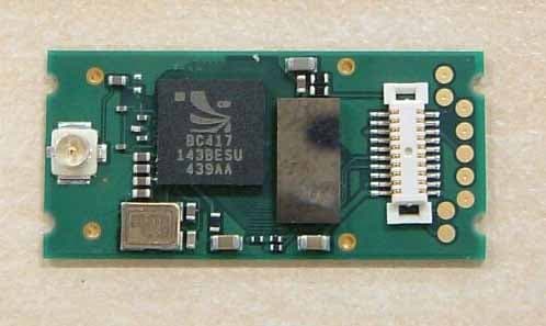
Click to zoom
Application Details
- Equipment Class
- PCB - PCS Licensed Transmitter
- Date of Grant
- Apr 09, 2006
- Application Purpose
- Original Equipment
- Date of Application
- Feb 01, 2006
- Equipment Note
- Laptop with wireless radios
- Frequency Range
- 1850.20000000 - 1909.80000000
- Company
- Sony Group Corporation
- Country
- Japan
Documents & Files
Document Text
Text extracted from the exhibit documents filed with the FCC. Open a document above to read the original.
Users Manual
N User Guide Personal Computer VGN-SZ100 Series 2 nN Contents Before Use .........................................................................................................................................................................6 Documentation .............................................................................................................................................................6 Ergonomic Considerations ...........................................................................................................................................8 Getting Started .................................................................................................................................................................10 Locating Controls and Ports.......................................................................................................................................11 About the Indicator Lights ..........................................................................................................................................17 Connecting a Power Source ......................................................................................................................................19 Using the Battery Pack ..............................................................................................................................................20 Shutting Down Your Computer Safely .......................................................................................................................25 Using Your VAIO Computer .............................................................................................................................................26 Using the Keyboard ...................................................................................................................................................27 Using the Touch Pad .................................................................................................................................................29 Using Special-function Buttons ..................................................................................................................................30 Using the Built-in MOTION EYE Camera...................................................................................................................31 Using the Optical Disc Drive ......................................................................................................................................32 Using PC Cards .........................................................................................................................................................42 Using the ExpressCard/34 Media ..............................................................................................................................45 Using the Memory Stick Media ..................................................................................................................................48 Using Other Memory Cards .......................................................................................................................................53 Using the Internet.......................................................................................................................................................57 Using Wireless LAN (WLAN) .....................................................................................................................................58 Using the Bluetooth Functionality ..............................................................................................................................68 3 nN Using Peripheral Devices .................................................................................................................................................75 Connecting a Docking Station....................................................................................................................................76 Connecting External Speakers ..................................................................................................................................85 Connecting an External Display .................................................................................................................................86 Selecting Display Modes............................................................................................................................................90 Using the Multiple Monitors Function .........................................................................................................................91 Connecting an External Microphone ..........................................................................................................................93 Connecting a Universal Serial Bus (USB) Device......................................................................................................94 Connecting a Printer ..................................................................................................................................................97 Connecting an i.LINK Device .....................................................................................................................................98 Connecting to a Network (LAN) ...............................................................................................................................100 Customizing Your VAIO Computer ................................................................................................................................102 Selecting Performance Modes .................................................................................................................................103 Setting the Password ..................................................................................................................................…
Text truncated - open the document above for the full version.
Users Manual
Personal Computer VGN-TX600 Series SmartWi Connection Utility Guide VAIO® Computer Wireless Information 2 Table of Contents About your Computer........................................... 3 Contents .................................................................................... 3 About Wireless Connectivity .................................................... 4 About the SIM Card .................................................................. 4 About Wireless Connection Utility ...................... 9 Starting SmartWi Connection Utility........................................ 9 About the Wireless Switching Window ............ 12 Using the Wireless Switching Window .................................. 12 Using SmartWi Connection Utility .................... 13 Using the Cingular WWAN connection ................................. 13 Using the Wireless LAN connection ...................................... 15 Using the Bluetooth® connection ........................................... 20 General Functional Information ........................ 22 FAQ and Troubleshooting ................................. 23 Notice to Users ................................................... 33 About your Computer 3 About your Computer Thank you for purchasing a VAIO® VGN-TX600 Series computer! Your new machine combines state-of-the-art hardware and software to bring you unparalleled wireless connectivity. Contents These hardware components are included. * A Cingular SIM card is preinstalled in your computer. Carton Contents Computer* Power cord Battery AC adapter VAIO® Computer Wireless Information 4 About Wireless Connectivity With built-in Wireless WAN capabilities, your computer is equipped to connect wirelessly to your e-mail, the Internet, and any intranet networks with which you may be associated. To begin making use of wireless connectivity, you will need to insert a provided Subscriber Identity Module (SIM) card into the computer before turning on your computer. About the Cingular SIM Card The SIM card, provided by Cingular Wireless, is a small printed circuit board that stores data identifying the user to the network service provider. It must be inserted into the computer for you to make use of the wireless services. Inserting the Cingular SIM card The Cingular SIM card should be preinstalled; you may follow these procedures to verify that the SIM card is indeed installed in the SIM card slot at the rear of your computer. ✍ Only the Cingular SIM card is supported. It is normally preinstalled in your computer. Do not touch the SIM card connectors. As a precaution, always make sure you have a firm hold of your computer before inserting or removing the SIM card. About the Cingular SIM Card 5 1Unless preinstalled, your SIM card is contained within a larger card, about the size of a credit card. Remove the smaller SIM card by pushing it out from the larger card. 2Next, orient your computer so you are facing its rear portion. 3Locate the SIM card slot in the back of the computer and with its printed circuit side facing down, gently insert the SIM card into the slot. Check the SIM card for directions on which way to orient the card into the slot. Cingular SIM Card ✍Before inserting the SIM card into the computer, make sure your computer is turned off and the battery is not attached. VAIO® Computer Wireless Information 6 If your computer came with a preinstalled Cingular SIM card, verify that the card is indeed in the SIM card slot. If a SIM card can not be found in the unit, there are two ways to obtain the card: 1Contact Sony’s VAIO PC support line (888)-476-6972 and request a free replacement SIM card. Please note that you must have the VAIO product model number and serial number to receive the replacement SIM from Sony. Subject to availability, the replacement SIM card will be shipped from Sony to you without charge. 2Go to the local Cingular store and ask for SIM card for local service. Additional cost would apply in this process. Inserting the SIM card SIM card (printed circuit side face down) Cut-off corner oriented left About the Cingular SIM Card 7 ✍To activate your Cingular account, call Sony customer support at 888-604-VAIO (8246). When calling customer support, you may be asked for the SIM# (IMSI #) and IMEI code. To determine these values, start the Cingular Connection Manager (CCM), open Tools, and click Network Info. Alternatively, you can check the the rear of your VAIO computer. The IMEI # and SIM # (ICCID) should be printed on the back of your computer. Removing the SIM Card To remove the SIM card, again orient your computer so you are facing its rear portion. Make sure the computer is turned off. 1Locate the SIM card slot. 2Gently push in the SIM card until you hear it click, then release the card allowing the SIM card to eject. After the SIM card ejects, gently pull the card out of the slot, away from the computer. Do not touch the SIM card connectors. As a precaution, make sure you have a firm hold of your computer before inserting or removing the SIM card. VAIO® Computer Wireless Information 8 Removing the SIM Card ✍Take care not to damage the card in any way, either by bending or putting undue pressure on the card. About SmartWi Connection Utility 9 About SmartWi Connection Utility The SmartWi Connection Utility functions largely as a switch manager between the various forms of wireless connectivity: Bluetooth®, WLAN, and WWAN using Cingular Wireless software. By clicking on each of the three wireless options, the SmartWi Connection Utility switches to the corresponding one. Starting SmartWi Connection Utility At initial statup, a pop-up prompt appears from the Task Tray. Selecting Yes on the prompt launches the SmartWi Connection Utility, and then you are prompted to activate your Cingular account. If you close the program, however, and later wish to restart it, do the following: SmartWi Connection Utility main screen VAIO® Computer Wireless Information 10 1First make sure your com…
Text truncated - open the document above for the full version.
Cover Letter(s)
Page 1 of 1 CETECOM Inc. 411 Dixon Landing Road Milpitas, CA 95035 U.S.A. Phone: + 1 408 586 6200 Fax: + 1 408 586 6299 e-mail: [email protected] URL: www.cetecom.com Statement The photographs mentioned in the temporary confidentiality letter include • Internal photos • External photos • Test setup photos Lothar Schmidt
Cover Letter(s)
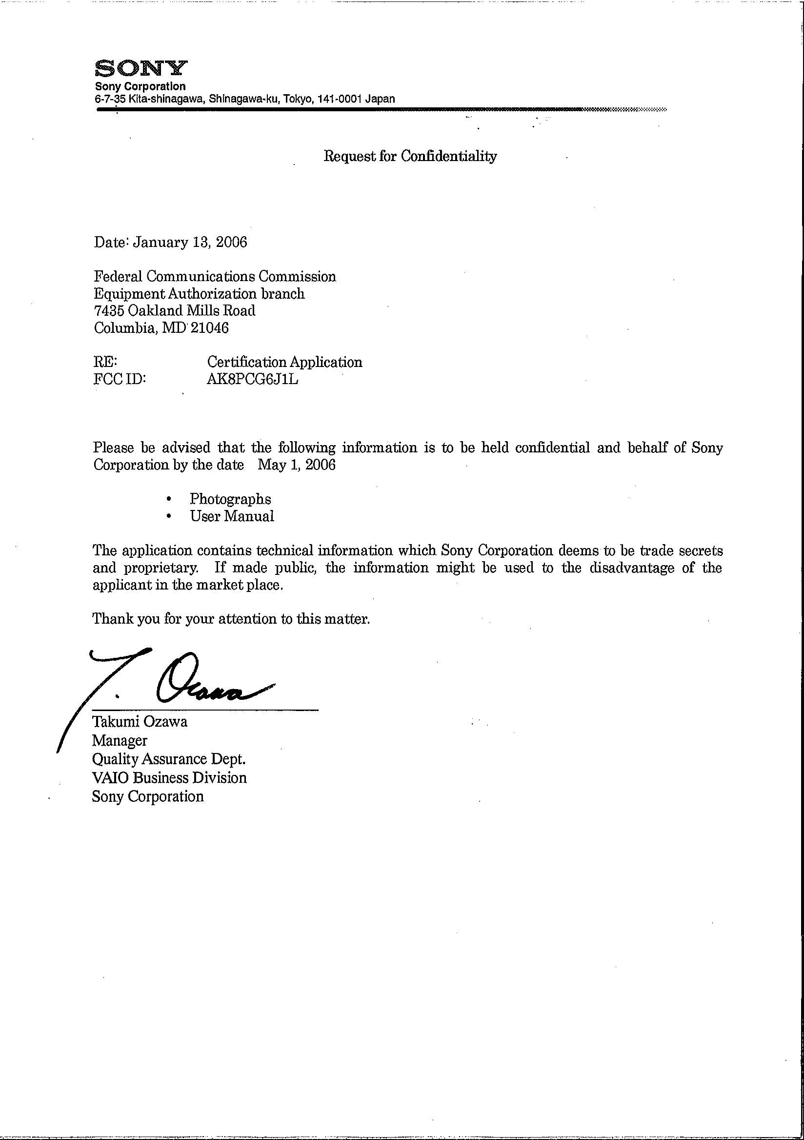
Federal Communication Commission Equipment Authorization Division, Application Processing Branch 7435 Oakland Mills Road Columbia, MD 21048 April 03, 2006 TO WHOM IT MAY CONCERN Pursuant to Paragraphs §0.457 and 0.459 of the Commission’s Rules (47 C.F.R.) and Section §552(b)(4) of the Freedom of Information Act, Sony Corporation requests confidentiality for the following products: FCC ID Number Product Title/Model AK8PCG6J1L Laptop PCG-6J1L, PCG-6L1L For the product stated above, we request that the following information be held confidential: 1) Electrical Schematics of the Circuitry 2) Block diagrams 3) Operational descriptions 4) Tune up procedures No other items submitted as part of the equipment authorization filing process are deemed confidential. The above exhibits contain Sony Corporation trade secrets and proprietary information that could be of benefit to our competitors regarding the design of our mobile handset. This material is not customarily available to the general public and we request that it be withheld from public inspection. If you have any questions, please feel free to contact me at the address shown below. Sincerely, Technical Manager CETECOM Inc.
External Photos
UGPZ6 Photo Top view Bottom view No shield cover
Internal Photos
UGPZ6 Photo Top view Bottom view No shield cover UGPZ6 Antenna LDA31 top view Bottom view CAN4313359 top view Bottom view C680 top view Bottom view
Internal Photos
PCG-6J1L Regulatory Antenna Information 1/4 PCG- 6J1L Regulatory Antenna Information Sony Corporation PCG-6J1L Regulatory Antenna Information 2/4 Section 1. Host Platform Information PCG-6J1L platform correlated to antenna data Section 2. Antenna Host Platform Location Information Include a dimensioned photos or dimensioned drawings of WLAN main and auxiliary antenna placements. 226.7 mm 314.2 mm 175.0 mm 218.1 mm AUX ANTENNA MAIN ANTENNA 218.1 mm PCG-6J1L Regulatory Antenna Information 3/4 Section 3. Antenna dimensional information for SAR evaluation Include a dimensioned photos or dimensioned drawings showing the distance (mm) between the transmit (main) antenna and the user (excluding hands, wrist, feet, and ankle) EDGE Antenna 232.5 247.0 289.5 Main Antenna PCG-6J1L Regulatory Antenna Information 4/4 Section 4. Diagram Example of Co-Location Antenna Separation Indicate distance between WLAN module antennas and Bluetooth/other radio antenna element. Indicate distance between EDGE module antennas and Bluetooth/other radio antenna element. Wireless WAN (EDGE) and Wireless LAN transmitter do not operates simultaneously. (Note: Due to the evolving rules regarding co-location, each platform will need to be reviewed on a case basis) 5.9 mm 153.9 mm OTHER ANTENNA (BLUETOOTH) 211.4 mm 200.0 mm OTHER MODULE (BLUETOOTH) WLAN MODULE 14.6 mm 2.0 mm 324.3 mm 223.2 mm AUX ANTENNA MAIN ANTENNA 85 mm 50 mm 106.5mm EDGE MODULE EDGE ANTENNA 175.0mm 297.0 mm
RF Exposure Info
TTI-P-G 081/94-A0 ACCREDITED ACCORDING TO ISO/IEC 17025 Bluetooth Qualification Test Facility (BQTF) FCC listed # 101450 IC recognized # 3925 CETECOM Inc. 411 Dixon Landing Road Milpitas, CA 95035 U.S.A. Phone: + 1 (408) 586 6200 Fax: + 1 (408) 586 6299 E-mail: [email protected] http://www.cetecom.com CETECOM Inc. is a Delaware Corporation with Corporation number: 2113686 Board of Directors: Dr. Harald Ansorge, Dr. Klaus Matkey, Hans Peter May V.2.16M-2002-03-12 \\stupendousman\rootappsdata\emc\projects_emc\sony_electronics\sonye_004_05002_ pcg_6jil_d_platform\2_test_reports\sar\sonye_001_05002_sar_fcc_850_1900.doc © Copyright by CETECOM SAR Test Report No.: SONYE_0014_05002_SAR_FCC_850_1900_2450 for the SONY Corporation Personal Computer Model Number: PCG-6J1L FCC ID: AK8PCG6J1L IC-ID: 409B-BPCG6J1L Date of Report: 1/20/2006 Date of issue: 1/20/2006 Report Copy No.: 01 SAR Test Report No. SONYE_0014_05002_SAR_FCC_850_1900_2450 Date of Report: 1/20/2006 Page 2 of 26 This report shall not be reproduced except in full without the written approval of: CETECOM Inc. SAR 411 Dixon Landing Road Milpitas, CA 95035 U.S.A. Contents 1 ASSESSMENT ...................................................................................................................4 2 ADMINISTRATIVE DATA...................................................................................................5 2.1 Identification of the Testing Laboratory Issuing the SAR Assessment Report ...............5 2.2 Identification of the Client...........................................................................................5 2.3 Identification of the Manufacturer...............................................................................5 3 EQUIPMENT UNDER INVESTIGATION (EUI)...................................................................6 3.1 Identification of the Equipment under Investigation ...................................................6 4 SUBJECT OF INVESTIGATION ........................................................................................7 4.1 The IEEE Standard C95.1 and the FCC Exposure Criteria .......................................7 4.2 Distinction Between Exposed Population, Duration of Exposure and Frequencies...7 4.3 Distinction between Maximum Permissible Exposure and SAR Limits......................8 4.4 SAR Limit ...................................................................................................................8 5 THE FCC MEASUREMENT PROCEDURE .......................................................................9 5.1 General Requirements...............................................................................................9 5.2 Test Positions ..........................................................................................................10 5.3 Body-worn and Other Configurations.......................................................................10 5.4 Procedure for assessing the peak spatial-average SAR .........................................10 5.5 Determination of the largest peak spatial-average SAR ..........................................12 6 THE MEASUREMENT SYSTEM ......................................................................................14 6.1 Robot system specification ......................................................................................14 6.2 Probe and amplifier specification .............................................................................15 6.3 Phantoms.................................................................................................................15 6.4 SAR measurement procedure .................................................................................16 6.5 SARA2 Interpolation and Extrapolation schemes ....................................................16 6.6 Interpolation of 2D area scan...................................................................................17 6.7 Extrapolation of 3D scan..........................................................................................17 6.8 Interpolation of 3D scan and volume averaging.......................................................17 SAR Test Report No. SONYE_0014_05002_SAR_FCC_850_1900_2450 Date of Report: 1/20/2006 Page 3 of 26 This report shall not be reproduced except in full without the written approval of: CETECOM Inc. SAR 411 Dixon Landing Road Milpitas, CA 95035 U.S.A. 7 UNCERTAINTY ASSESSMENT.......................................................................................19 7.1 Table of Measurement Uncertainty Values of SAR Evaluations..............................20 7.2 Table of Measurement Uncertainty Values for SAR System Verification ................20 8 TEST RESULTS SUMMARY............................................................................................22 8.1 Radiated Output Power............................................................................................22 8.2 Test Positions and Configurations ...........................................................................22 8.3 BT colocated ............................................................................................................22 8.4 1900 MHz band SAR Results for PCG-6J1L ...........................................................23 8.5 Validation Check Results .........................................................................................24 9 REFERENCES..................................................................................................................26 SAR Test Report No. SONYE_0014_05002_SAR_FCC_850_1900_2450 Date of Report: 1/20/2006 Page 4 of 26 This report shall not be reproduced except in full without the written approval of: CETECOM Inc. SAR 411 Dixon Landing Road Milpitas, CA 95035 U.S.A. 1 Assessment The SONY Corporation PCG-6J1L Personal Computer, FCC ID: AK8PCG6J1L, is in compliance with the limits for general population uncontro…
Text truncated - open the document above for the full version.
RF Exposure Info
SAR Test Report No.: SONYE_004_05002_SAR_FCC_850_1900 Date of Report: 01/20/2006 Appendix A Plots Page 1 of 8 System / software: SARA2 / 2.3 VPM Input Power Drift: Date / Time: 1/16/2006 10:23:21 AM DUT Battery Model/No: Filename: 190lapv_3d.txt Probe Serial Number: 0123 Ambient Temperature: 22.0°C Liquid Simulant: 850 Device Under Test: Sony D platform Relative Permittivity: 55.55 Relative Humidity: 50% Conductivity: 0.987 Phantom S/No: HeadBox_new_spout.c sv Liquid Temperature: 22.0°C Phantom Rotation: 0° Max SAR Y-axis Location: -22.67 mm DUT Position: lap Max SAR Z-axis Location: -165.00 mm Antenna Configuration: vertical Max E Field: 13.02 V/m Test Frequency: 836.6MHz SAR 1g: 0.149 W/kg Air Factors: 346 / 318 / 386 SAR 10g: 0.106 W/kg Conversion Factors: .522 / .522 / .522 SAR Start: 0.072 W/kg Type of Modulation: SAR End: 0.073 W/kg Modn. Duty Cycle: SAR Drift during Scan: 0.03 dB Diode Compression Factors (V*200): 10 / 11.7 / 7.7 Probe battery last changed: 01/11/2006 Input Power Level: max Extrapolation: poly4 SAR Test Report No.: SONYE_004_05002_SAR_FCC_850_1900 Date of Report: 01/20/2006 Appendix A Plots Page 2 of 8 . System / software: SARA2 / 2.3 VPM Input Power Drift: Date / Time: 1/16/2006 11:22:51 AM DUT Battery Model/No: Filename: 190laph_3d.txt Probe Serial Number: 0123 Ambient Temperature: 22.0°C Liquid Simulant: 850 Device Under Test: Sony D platform Relative Permittivity: 55.55 Relative Humidity: 50% Conductivity: 0.987 Phantom S/No: HeadBox_new_spout.c sv Liquid Temperature: 22.0°C Phantom Rotation: 0° Max SAR Y-axis Location: 0.00 mm DUT Position: lap Max SAR Z-axis Location: -146.40 mm Antenna Configuration: horizontal Max E Field: 10.23 V/m Test Frequency: 836.6MHz SAR 1g: 0.091 W/kg Air Factors: 346 / 318 / 386 SAR 10g: 0.063 W/kg Conversion Factors: .522 / .522 / .522 SAR Start: 0.043 W/kg Type of Modulation: SAR End: 0.043 W/kg Modn. Duty Cycle: SAR Drift during Scan: 0.00 dB Diode Compression Factors (V*200): 10 / 11.7 / 7.7 Probe battery last changed: 01/11/2006 Input Power Level: max Extrapolation: poly4 SAR Test Report No.: SONYE_004_05002_SAR_FCC_850_1900 Date of Report: 01/20/2006 Appendix A Plots Page 3 of 8 System / software: SARA2 / 2.3 VPM Input Power Drift: Date / Time: 1/16/2006 12:46:27 PM DUT Battery Model/No: Filename: 128lapv_3d.txt Probe Serial Number: 0123 Ambient Temperature: 22.0°C Liquid Simulant: 850 Device Under Test: Sony D platform Relative Permittivity: 56.07 Relative Humidity: 50% Conductivity: 0.973 Phantom S/No: HeadBox_new_spout.c sv Liquid Temperature: 22.0°C Phantom Rotation: 0° Max SAR Y-axis Location: -16.00 mm DUT Position: lap Max SAR Z-axis Location: -164.00 mm Antenna Configuration: vertical Max E Field: 12.65 V/m Test Frequency: 824.2MHz SAR 1g: 0.138 W/kg Air Factors: 346 / 318 / 386 SAR 10g: 0.096 W/kg Conversion Factors: .522 / .522 / .522 SAR Start: 0.064 W/kg Type of Modulation: SAR End: 0.065 W/kg Modn. Duty Cycle: SAR Drift during Scan: 0.05 dB Diode Compression Factors (V*200): 10 / 11.7 / 7.7 Probe battery last changed: 01/11/2006 Input Power Level: max Extrapolation: poly4 SAR Test Report No.: SONYE_004_05002_SAR_FCC_850_1900 Date of Report: 01/20/2006 Appendix A Plots Page 4 of 8 System / software: SARA2 / 2.3 VPM Input Power Drift: Date / Time: 1/16/2006 2:37:33 PM DUT Battery Model/No: Filename: 251lapv_3d.txt Probe Serial Number: 0123 Ambient Temperature: 22.0°C Liquid Simulant: 850 Device Under Test: Sony D platform Relative Permittivity: 55.46 Relative Humidity: 50% Conductivity: 0.983 Phantom S/No: HeadBox_new_spout.c sv Liquid Temperature: 22.0°C Phantom Rotation: 0° Max SAR Y-axis Location: -6.00 mm DUT Position: lap Max SAR Z-axis Location: -174.67 mm Antenna Configuration: vertical Max E Field: 22.67 V/m Test Frequency: 848.8MHz SAR 1g: 0.130 W/kg Air Factors: 346 / 318 / 386 SAR 10g: 0.085 W/kg Conversion Factors: .522 / .522 / .522 SAR Start: 0.054 W/kg Type of Modulation: SAR End: 0.054 W/kg Modn. Duty Cycle: SAR Drift during Scan: 0.00 dB Diode Compression Factors (V*200): 10 / 11.7 / 7.7 Probe battery last changed: 01/11/2006 Input Power Level: max Extrapolation: poly4 SAR Test Report No.: SONYE_004_05002_SAR_FCC_850_1900 Date of Report: 01/20/2006 Appendix A Plots Page 5 of 8 . System / software: SARA2 / 2.3 VPM Input Power Drift: Date / Time: 1/11/2006 1:53:17 PM DUT Battery Model/No: Filename: lap661v_3d.txt Probe Serial Number: 0123 Ambient Temperature: 22.0°C Liquid Simulant: 1900 Device Under Test: Sony D platform Relative Permittivity: 53.21 Relative Humidity: 50% Conductivity: 1.577 Phantom S/No: HeadBox_new_spout.c sv Liquid Temperature: 22.0°C Phantom Rotation: 0° Max SAR Y-axis Location: -28.00 mm DUT Position: lap Max SAR Z-axis Location: -156.00 mm Antenna Configuration: vertical Max E Field: 9.57 V/m Test Frequency: 1880MHz SAR 1g: 0.118 W/kg Air Factors: 346 / 318 / 386 SAR 10g: 0.065 W/kg Conversion Factors: 0.666 / 0.666 / 0.666 SAR Start: 0.036 W/kg Type of Modulation: SAR End: 0.036 W/kg Modn. Duty Cycle: SAR Drift during Scan: 0.01 dB Diode Compression Factors (V*200): Probe battery last changed: 10 / 11.7 / 7.7 01/11/2006 Input Power Level: Extrapolation: max poly4 SAR Test Report No.: SONYE_004_05002_SAR_FCC_850_1900 Date of Report: 01/20/2006 Appendix A Plots Page 6 of 8 System / software: Input Power Drift: SARA2 / 2.3 VPM Date / Time: DUT Battery Model/No: 1/11/2006 3:05:39 PM Filename: lap661h_3d.txt Probe Serial Number: 0123 Ambient Temperature: 22.0°C Liquid Simulant: 1900 Device Under Test: Relative Permittivity: Sony D platform 53.21 Relative Humidity: 50% Conductivity: 1.577 HeadBox_new_spout.c sv Liquid Temperature: Phantom S/No: 22.0°C Phantom Rotation: 0° Max SAR Y-axis Location: -23.33 mm DUT Position: lap Max SAR Z-axis Location: -162.00 mm Antenna Configuration: horizontal Max E Field: 10.91 V/m Test Frequency: 1880MHz SAR 1g: 0.157 W/kg Air Factors: SAR 10g: 346 / 318 / 386 0.094 W/kg Conversion Factors: SAR Start: 0.666 / 0.666 / 0.666 0.047 W/kg Type of Modu…
Text truncated - open the document above for the full version.
RF Exposure Info
CETECOM Inc. 411 Dixon Landing Road Milpitas, CA 95035 Federal Communication Commission 02/02/2006 Authorization and Evaluation Division 7435 Oakland Mills Road Columbia, MD 21046 Attention: Reviewing Engineer Company: Sony Corporation Model: PCG-6J1L FCC ID: AK8PCG6J1L Due to the construction and the position of the antenna a distance under normal operating conditions of more than 20 cm is guaranteed. Regarding MPE limits, GPUC environment limits maximum exposure to 1 mW/cm 2. The power density is: S = E 2 /3770=-13 H 2 = limit < 1 mW/cm 2 Where: S = Power density (mW/cm 2) E = electrical field strength (V/m) This formula converted using the EIRP is P out *G/4π*r 2 mW/cm 2 Maximum EIRP 2400 MHz band: 0.56W at 2412 MHz 560/4π*400 = 0.11 mW/cm 2 at 20 cm. Maximum EIRP 5000 MHz band: 0.186W at 5825 MHz 186/4π*400 = 0.04 mW/cm 2 at 20 cm. Calculations are based on standard formula for calculating field strength at a distance and converting power density using free space impedance. If you should have any questions regarding this submission, please feel free to contact the undersigned. Yours truly, Lothar Schmidt Technical Manager EMC/Radio CETECOM Inc.
Test Report
CETECOM ICT Services GmbH Untertürkheimer Str. 6-10, 66117 Saarbruecken Phone: +49 (0) 681 598-0 Fax: -9075 RSC-Laboratory Phone: +49 (0) 681 598-0 Fax: -9075 Test report no.: 2-3875-01-01/05 Date: 2005-02-21 Page 1 of 80 Recognized by the Federal Communications Commission Anechoic chamber registration no.: 90462 (FCC) Anechoic chamber registration no.: 3463 (IC) TCB ID: DE 0001 Accredited by the German Accreditation Council DAR–Registration Number TTI–P–G 081/94-D0 Independent ETSI compliance test house ETSI Accredited Bluetooth ® Test Facility (BQTF) Test report no. : 2-3875-01-01/05 Applicant :Sony Ericsson Mobile Communication AB Type :Sony Ericsson EE52 type FAF- 1031021-BV Test Standard :FCC Part 22, 24 RSS132, 133 FCC ID :PY7FF031021 Certification No. IC :4170B-FF031021 CETECOM ICT Services GmbH Untertürkheimer Str. 6-10, 66117 Saarbruecken Phone: +49 (0) 681 598-0 Fax: -9075 RSC-Laboratory Phone: +49 (0) 681 598-0 Fax: -9075 Test report no.: 2-3875-01-01/05 Date: 2005-02-21 Page 2 of 80 Table of contents 1 GENERAL INFORMATION ................................................................................................................................... 3 1.1. ADMINISTRATIVE DATA OF THE TEST FACILITY..................................................................................................... 3 1.1.1 Identification of the testing laboratory ......................................................................................................... 3 1.2. NOTES................................................................................................................................................................... …
Text truncated - open the document above for the full version.
Contact Information
Applicant
Kazuyuki Hori(Chief EMC/RF Compliance Specialist)
Technical Contact
CETECOM Inc.Lothar Schmidt
[email protected]408-586-6214
411 Dixon Landing Road · Milpitas, California · United States
Non-Technical Contact
CETECOM Inc.Lothar Schmidt
[email protected]408 586 6214
Test Firm
Cetecom Inc.Lothar Schmidt
Technical Specifications
| # | Rule Parts | Frequency Range | Power Output | Emission | Tolerance |
|---|---|---|---|---|---|
| 2 | 24E | 1.85 GHz - 1.91 GHz | 740.00 mW | 300KGXW | 0.0346 ppm |
Other Applications from Sony Group Corporation
AK8WW81782
Aug 21, 2026Radio Equipment
Equipment Class
DSS - Part 15 Spread Spectrum TransmitterAK8CFIZCP2
Aug 03, 2026Wireless Controller
Equipment Class
DSS - Part 15 Spread Spectrum TransmitterAK8OEV321MUH
Apr 14, 2026LCD Monitor
Equipment Class
JAD - Part 15 Class A Digital DeviceAK8OEV431MUH
Apr 14, 2026LCD Monitor
Equipment Class
JAD - Part 15 Class A Digital DeviceAK8OEV271MUH
Apr 14, 2026LCD Monitor
Equipment Class
JAD - Part 15 Class A Digital Device