AK8PCG9D1RNotebook Personal Computer with built in WLAN card
Sony Group Corporation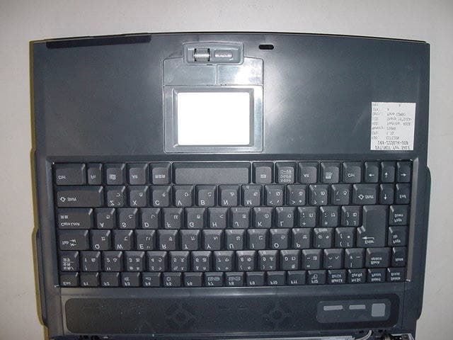
Click to zoom
Application Details
- Equipment Class
- DSS - Part 15 Spread Spectrum Transmitter
- Date of Grant
- Apr 17, 2002
- Application Purpose
- Original Equipment
- Date of Application
- Apr 17, 2002
- Equipment Note
- Notebook Personal Computer with built in WLAN card
- Frequency Range
- 2412.00000000 - 2462.00000000
- Company
- Sony Group Corporation
- Country
- Japan
Documents & Files
Document Text
Text extracted from the exhibit documents filed with the FCC. Open a document above to read the original.
Users Manual
VAIO® Computer Safety Information PCG-NV170 Series Notes on Use 2 Notice to Users © 2002 Sony Electronics Inc. All rights reserved. This manual and the software described herein, in whole or in part, may not be reproduced, translated, or reduced to any machine-readable form without prior written approval. SONY ELECTRONICS INC. PROVIDES NO WARRANTY WITH REGARD TO THIS MANUAL, THE SOFTWARE, OR OTHER INFORMATION CONTAINED HEREIN AND HEREBY EXPRESSLY DISCLAIMS ANY IMPLIED WARRANTIES OF MERCHANTABILITY OR FITNESS FOR ANY PARTICULAR PURPOSE WITH REGARD TO THIS MANUAL, THE SOFTWARE, OR SUCH OTHER INFORMATION. IN NO EVENT SHALL SONY ELECTRONICS INC. BE LIABLE FOR ANY INCIDENTAL, CONSEQUENTIAL, OR SPECIAL DAMAGES, WHETHER BASED ON TORT, CONTRACT, OR OTHERWISE, ARISING OUT OF OR IN CONNECTION WITH THIS MANUAL, THE SOFTWARE, OR OTHER INFORMATION CONTAINED HEREIN OR THE USE THEREOF. Sony Electronics Inc. reserves the right to make any modification to this manual or the information contained herein at any time without notice. The software described herein is governed by the terms of a separate user license agreement. This product contains software owned by Sony and licensed by third parties. Use of such software is subject to the terms and conditions of license agreements enclosed with this product. Some of the software may not be transported or used outside the United States. Software specifications are subject to change without notice and may not necessarily be identical to current retail versions. Updates and additions to software may require an additional charge. Subscriptions to online service providers may require a fee and credit card information. Financial services may require prior arrangements with participating financial institutions. The International ENERGY STAR® Office Equipment Program is an international program that promotes energy saving through the use of computers and other office equipment. The program backs the development and dissemination of products with functions that effectively reduce energy consumption. It is an open system in which business proprietors can participate voluntarily. The targeted products are office equipment such as computers, displays, printers, facsimiles and copiers. Their standards and logos are uniform among participating nations. ENERGY STA R i s a U . S . registered mark. As an ENERGY STAR® Partner, Sony Corporation has determined that this product meets the ENERGY STAR® guidelines for energy efficiency. Notice to Users 3 Sony, DVgate, Handycam, i.LINK, Mavica, MagicGate™ Memory Stick and , Memory Stick and , MovieShaker, PictureToy, VAIO, and the VAIO logo are trademarks of Sony Corporation. Microsoft, Windows Media, Windows, Windows NT, and the Windows logo are registered trademarks of Microsoft Corporation. Intel, SpeedStep, and Pentium are trademarks or registered trademarks of Intel Corporation. PS/2 is a registered trademark of IBM. Acrobat Reader, Photoshop, Photoshop Elements, and Premiere are trademarks of Adobe Systems Incorporated. PowerPanel is a trademark of Phoenix Technologies Ltd. This product incorporates copyright protection technology that is protected by method claims of certain U.S. patents and other intellectual property rights owned by Macrovision Corporation and other rights owners. Use of this copyright protection technology must be authorized by Macrovision Corporation, and is intended for home and other limited viewing uses only unless otherwise authorized by Macrovision Corporation. Reverse engineering or disassembly is prohibited. i.LINK is a trademark of Sony used only to designate that a product contains an IEEE 1394 connection. The i.LINK connection may vary, depending on the software applications, operating system, and compatible i.LINK devices. All products with an i.LINK connection may not communicate with each other. Please refer to the documentation that came with your compatible i.LINK device for information on operating conditions and proper connection. Before connecting compatible i.LINK PC peripherals to your system, such as a CD-RW or hard disk drive, confirm their operating system compatibility and required operating conditions. All other trademarks are trademarks of their respective owners. Microsoft note Certain software product(s) included with this computer may include features such as copy protection and content management technology. Use of the software product(s) requires agreement to applicable end user agreements and full compliance with applicable product activation procedures. Product activation procedures and privacy policies will be detailed during initial launch of the software product(s), or upon certain reinstallations of the software product(s) or reconfiguration of the computer, and may be completed by Internet or telephone (toll charges may apply). The Wireless LAN PC card * which is incorporated into this unit has passed Wi-Fi certification, and complies with the interoperability specifications established by WECA (Wireless Ethernet Compatibility Alliance). * Wireless LAN PC card is available in selected models. MEMORY STICK TM Notes on Use 4 Owner’s Record The model number and serial number are located on the bottom of your Sony VAIO Computer. Refer to the model and serial number when you call your Sony Service Center. Model Numbers: PCG-9D1L, PCG-9D6L, PCG-9D1R, PCG-9D2R Serial Number:________________________ Safety Information WARNING ❑ To prevent fire or shock hazard, do not expose your computer to rain or moisture. ❑To avoid electrical shock, do not open the cabinet. Refer servicing to qualified personnel only. ❑Never install modem or telephone wiring during a lightning storm. ❑Never install telephone jacks in wet locations unless the jack is specifically designed for wet locations. ❑Never touch uninsulated telephone wire or terminals unless the telephone line has been disconnected at the network interface. ❑Use caution when installing or modifying telephone lines. ❑Avoid using the …
Text truncated - open the document above for the full version.
Users Manual
1 Contents Welcome.......................................................9 Using Your VAIO Computer .....................11 Using the Keyboard...................................................12 Combinations and functions with the Windows key .........14 Indicators ...........................................................................15 Indicator lights ...................................................................15 Combinations and functions with the Fn key ....................16 Using the Touchpad ..................................................18 VAIO Action Setup ...................................................20 Using the Center Jog Dial Control ............................21 Using the center Jog Dial Control......................................21 Launcher mode ..................................................................22 Guide mode ........................................................................23 Center Jog Dial back button...............................................23 Using the center Jog Dial Control with Sony software .....24 Using the center Jog Dial Control with other software .....24 Using the Optical Disc Drive ....................................25 To insert a disc ...................................................................25 To eject a disc ....................................................................26 To play a DVD...................................................................27 To play an audio CD ..........................................................28 Notes on CD and DVD discs .............................................28 To write data to a CD-RW or CD-R disc...........................29 Change text in this variable definition to document title. 2 Using PC Cards......................................................... 30 To insert a PC Card ........................................................... 30 To remove a PC Card........................................................ 31 Using Memory Stick Media.................................... 32 Types of Memory Stick media.......................................... 32 Write-protecting Memory Stick media ............................. 34 Formatting Memory Stick media ...................................... 34 Notes on using Memory Stick media ................................ 35 Using the Multipurpose Bay ..................................... 37 To install a device into the multipurpose bay ................... 37 To remove the device from the multipurpose bay ............ 38 Notes on using a device in the multipurpose bay.............. 38 Using the Floppy Disk Drive .................................... 39 To insert a floppy disk into the floppy disk drive ............. 39 To remove a floppy disk from the floppy disk drive ........ 40 Notes on handling floppy disks......................................... 40 Using Power Saving Modes...................................... 41 Normal mode..................................................................... 41 Standby mode.................................................................... 41 Hibernate mode ................................................................. 41 Notes on power saving modes .......................................... 42 Using a Telephone Cable .......................................... 43 Using a Local Area Network .................................... 44 Setting up your Ethernet connection ................................. 44 3 Using Wireless LAN .................................................45 Turning On Wireless LAN ................................................45 The Wireless LAN Access Point .......................................46 Communicating with an Access Point (infrastructure) ......47 Communicating without an access point (ad-hoc).............48 Checking your connection status .......................................50 Turning Off Wireless LAN ................................................50 Notes on using Wireless LAN ...........................................51 Connecting Peripheral Devices ...............53 Connecting a USB Device.........................................54 To connect a USB device...................................................54 Connecting a USB Printer .........................................55 To connect a USB printer ..................................................55 Connecting a Parallel Port Printer .............................56 To connect to a parallel port printer...................................56 Connecting an Audio Device ....................................57 To connect an audio device ...............................................57 Connecting an Audio-Video Device .........................58 To connect an AV device...................................................58 To change the display ........................................................59 Connecting an i.LINK Audio-Video Device.............60 To connect a digital video camera recorder .......................60 Notes on connecting an i.LINK device..............................61 Connecting an External Display................................62 To connect a computer display ..........................................62 To connect a multimedia computer display .......................62 To connect a projector .......................................................63 Changing the display when connecting an external computer display or projector ............................................................64 Change text in this variable definition to document title. 4 Connecting with another VAIO computer................ 65 To connect two VAIO computers ..................................... 65 Connecting External Speakers .................................. 67 To connect external speakers ............................................ 67 Notes on connecting external speakers ............................. 67 Connecting an External Microphone ........................ 68 To connect an ext…
Text truncated - open the document above for the full version.
External Photos
Sony Corporation FCC ID: AK8PCG9D1R External Photos: Top Bottom Sony Corporation FCC ID: AK8PCG9D1R Front Back Sony Corporation FCC ID: AK8PCG9D1R Left Right Sony Corporation FCC ID: AK8PCG9D1R Palm Antenna Position Sony Corporation FCC ID: AK8PCG9D1R Antenna Left Position Antenna Left Position Sony Corporation FCC ID: AK8PCG9D1R Antenna Right Position Antenna Right Position Sony Corporation FCC ID: AK8PCG9D1R Antenna (Side A) Antenna (Side B)
Operational Description
COMPANY CONFIDENTIAL REV.1.0 2002/03/2211 1 T 60H424.00 MRS.doc T60H424.00 MINIPCI IIIB Wireless LAN Card Marketing Requirements Specification COMPANY CONFIDENTIAL REV.1.0 2002/03/2211 2 T 60H424.00 MRS.doc 0. REVISION HISTORY.............................................................................................................................................. 3 1. INTRODUCTION..................................................................................................................................................... 4 1. INTRODUCTION..................................................................................................................................................... 4 1.1 SCOPE................................................................................................................................................................... 4 1.2 W IRELESS LAN F UNCTION ................................................................................................................................... 4 2. PRODUCT REQUIREMENTS ............................................................................................................................... 5 2.1 G ENERAL E LECTRICAL S PECIFICATIONS ................................................................................................................ 5 2.2 HARDWARE ARCHITECTURE................................................................................................................................. 5 2.3 M ECHANICAL R EQUIREMENTS .............................................................................................................................. 6 2.4 WEIGHT................................................................................................................................................................ 6 2.5 ANTENNA CONNECTION........................................................................................................................................ 6 3. RELIABILITY, MAINTAINABILITY AND QUALITY...................................................................................... 7 3.1 R ELIABILITY .......................................................................................................................................................... 7 3.2 MAINTAINABILITY................................................................................................................................................. 7 3.3 QUALITY............................................................................................................................................................... 7 4. ENVIRONMENTAL REQUIREMENTS ............................................................................................................... 7 4.1 TEMPERATURE...................................................................................................................................................... 7 4.1.1 Operating Temperature Conditions.............................................................................................................. 7 4.1.2 Non-Operating Temperature Conditions...................................................................................................... 7 4.2 H UMIDITY ............................................................................................................................................................. 7 4.2.1 Operating Humidity Conditions ................................................................................................................... 7 4.2.2 Non-Operating Humidity conditions ............................................................................................................ 7 COMPANY CONFIDENTIAL REV.1.0 2002/03/2211 3 T 60H424.00 MRS.doc 0. Revision History Date: June 11, 2001 REV.0.1 Date: June 22, 2001 REV.0.2 Date: Mar 21, 2001 REV.1.0 COMPANY CONFIDENTIAL REV.1.0 2002/03/2211 4 T 60H424.00 MRS.doc 1. Introduction Project Name : MINIPCI IIIB Wireless LAN Card Project Code : T60H424.00 This documentation describes the marketing requirements specification of the Ambit MINIPCI IIIB Wireless LAN card using a RF Module based on Intersil’s Prism 2.5 chipsets. It is a confidential document of AMBIT. 1.1 Scope AMBIT MINIPCI IIIB WLAN Card complied with IEEE 802.11b 11Mbps Standard. The WLAN application is implemented via a RF module. This RF module is developed for Wireless LAN application complied with IEEE 802.11b 11Mbps standard in ISM band. It can be used to provide a variety of low-cost wireless network interfaces to build your wireless connection via simply SMT procedure to speed the time to market. Three Intersil’s chips are implemented in the RF module including ISL3984, ISL3685, HFA3783. 1.2 Wireless LAN Function z Compatible with IEEE 802.11b high rate standard to provide wireless Ethernet speeds of 11Mbps data rate z Dynamic data rate switching with 11, 5.5, 2 and 1Mbps z Allows auto fallback data rate for optimized reliability, throughput and transmission range z Supports wireless data encryption with 64/128-bit WEP standard for security z Dual diversity antenna connectors supported for the multi-path environment z Drivers supports Windows 95, 98, 98SE, NT, ME, 2000, XP . COMPANY CONFIDENTIAL REV.1.0 2002/03/2211 5 T 60H424.00 MRS.doc 2. Product Requirements 2.1 General Electrical Specifications Radio Technology IEEE 802.11b Direct Sequence Spread Spectrum Operating Frequency 2400 ~ 2474MHz ISM band Modulation Schemes DQPSK, DBPSK and CCK Channel Numbers IEEE 802.11b compliant 11 channels for United States Data Rate 11Mbps with fall back rates of 5.5, 2, and 1Mbps Spreading 11-chip Barker Sequence Media Access Protocol CSMA/CA with ACK Transmitter Output Power 15dBm typically Receiver Sensitivity Typical –85dBm for 11Mbps @ 8% PER Typical –90dBm for 2Mbps @ 8% PER Antenna Type Integrated diversity switch with HRS connectors for connecting dual diversity antennas Operating Voltage 3.3VDC …
Text truncated - open the document above for the full version.
RF Exposure Info
RF Exposure Statement No. : 22GE0004-YW-1 Applicant: SONY Corporation Type of Equipment: Notebook Personal Computer Model No.: PCG-9D1R FCC ID: AK8PCG9D1R A-PEX International Co., Ltd. YOKOWA LAB. 108 Yokowa-cho, Ise-shi, Mie-ken 516-1106 JAPAN Telephone:int +81 596 39 1485 Facsimile: int +81 596 39 0232 Page 1 FCC Radiation Exposure Statement: SONY Corporation Model : PCG-9D1R complies with FCC radiation exposure requirement specified in the FCC Rules 15.247(b)(4). Notice in Installation Manual CAUTION This equipment complies with FCC radiation exposure limits set forth for an uncontrolled environment. This equipment should be installed and operated with minimum distance 20cm between the radiator and body (excluding extremities: hands, wrists and feet) and must not be co-located or operated with any antenna or transmitter. RF Exposure Calculations: The following information provides the minimum separation distance for the highest gain antenna provided with the “PCG-9D1R” as calculated from FCC OET 65 Appendix B, Table (B) Limits for General Population / Uncontrolled Exposure. This calculation is based on the highest EIRP possible from the system, considering maximum power and antenna gain, and considering a 1.0m W/cm^2 uncontrolled exposure limit. The Fires formula used was: S = (P * G) / (4* * r^2) or r = (P * G) / (4 * * S) Where S = 1.0 mW/cm^2 for 2400 MHz P = 8.9mW (Maximum Conducted Power) G = 1.64(Half wavelength antenna gain : Converted absolute value) r = Minimum safe distance from antenna (cm) For: PCG-9D1R r = 1.1cm
Test Report
Page: 1 of 13 A-pex International Co., Ltd. YOKOWA LAB. 108 Yokowa-cho, Ise-shi, Mie-ken 516-1106 JAPAN Telephone:int +81 596 39 1485 Facsimile: int +81 596 39 0232 EMI TEST REPORT Test Report No. : 22GE0004-YW-1 Applicant: Sony Corporation Type of Equipment: Notebook Personal Computer (Wireless LAN built in PC) Model No.:PCG-9D1R FCC ID:AK8PCG9D1R Test standard:FCC Part15 Subpart C, Section 15.247 *Except FCC 15.247(e) Processing Gain Test Result:Complied This report may not be reproduced in full, partial reproduction may only be made with the written consent of the laboratory. The results in this report apply only to the sample tested. Date of test: March 11 and 12, 2002 Issued date: March 20, 2002 Tested by: Approved by: Naoki Sakamoto Kazutoyo Nakanishi Group Leader of EMC section Site Operation Manager of EMC section Test report FCC ID : AK8PCG9D1R Our reference : 22GE0004-YW-1 Page: 2 of 13 Issued date: March 20, 2002 A-pex International Co., Ltd. YOKOWA LAB. 108 Yokowa-cho, Ise-shi, Mie-ken 516-1106 JAPAN Telephone:int +81 596 39 1485 Facsimile: int +81 596 39 0232 Table of Contents Page 1 GENERAL INFORMATION3 1.1 Tested Methodology4 1.2 Test Facility4 2 PRODUCT DESCRIPTION5 2.1Test system Details5 3 SYSTEM TEST CONFIGURATION6 3.1 Justification6 3.2.Configuration of Tested System6 4 MEASUREMENT UNCERTAINTY7 5 SUMMARY OF TEST8 5.1 §15.207 Conducted Emissions8 5.2 §15.247(a)(2) 6dB Bandwidth (Antenna Port Conducted)8 5.3 §15.247(b) Maximum Peak Out Put Power (Antenna Port Conducted)9 5.4 §15.247(c) Out of Band Emissions (Radiated)9 5.5 §15.247(c) Out of Band Emissions (Antenna Port Conducted)10 5.6 §15.247(d) Power Density (Antenna Port Conducted)10 Photographs of test setup 11-12 APPENDIX13 Test dataA1toA33 Test Instruments A34 Test report FCC ID : AK8PCG9D1R Our reference : 22GE0004-YW-1 Page: 3 of 13 Issued date: March 20, 2002 A-pex International Co., Ltd. YOKOWA LAB. 108 Yokowa-cho, Ise-shi, Mie-ken 516-1106 JAPAN Telephone:int +81 596 39 1485 Facsimile: int +81 596 39 0232 1 GENERAL INFORMATION APPLICANT: Sony Corporation ADDRESS: 6-7-35 Kitashinagawa, Shinagawa-ku, Tokyo 141-0001 Japan TEL: 81-3-5795-8716 FAX: 81-3-5795-8981 REGULATION(S): FCC Part15 Subpart C, Section 15.247 *Except FCC 15.247(e) Processing Gain MODEL NUMBER: PCG-9D1R SERIAL NUMBER: 2230DVT1 0000057 (Conducted Antenna Port Emission test) 2230DVT1 0000067 (Conducted AC Mains and Radiated Emission test) KIND OF EQUIPMENT: Notebook Personal Computer (Wireless LAN built in PC) TESTED DATE: March 11 and 12, 2002 RECEIPT DATE OF SAMPLE : March 11, 2002 REPORT FILE NUMBER: 22GE0004-YW-1 TEST SITE : A-PEX Yokowa No.3 Open Test Sites Test report FCC ID : AK8PCG9D1R Our reference : 22GE0004-YW-1 Page: 4 of 13 Issued date: March 20, 2002 A-pex International Co., Ltd. YOKOWA LAB. 108 Yokowa-cho, Ise-shi, Mie-ken 516-1106 JAPAN Telephone:int +81 596 39 1485 Facsimile: int +81 596 39 0232 1.1 Tested Methodology The measurement was performed according to the procedures in ANSI C63.4(1992). 1.2 Test Facility The open area site measurement facilities used to collect the radiated data are located at 108, Yokowa-cho, Ise-shi, Mie-ken, 516-1106 Japan. These sites have been fully described in reports submitted to the FCC office. No.1 and No.3 test site has filed to the FCC on September 12, 2000 as number: 90412 and is accepted by Industry Canada on May 01, 2001 as number IC2973-3. Test report FCC ID : AK8PCG9D1R Our reference : 22GE0004-YW-1 Page: 5 of 13 Issued date: March 20, 2002 A-pex International Co., Ltd. YOKOWA LAB. 108 Yokowa-cho, Ise-shi, Mie-ken 516-1106 JAPAN Telephone:int +81 596 39 1485 Facsimile: int +81 596 39 0232 2 PRODUCT DESCRIPTION Sony Corporation, Model PCG-9D1R (referred to as the EUT in this report) is a Notebook Personal Computer. The specification is as following : LAN Module Frequency characteristies: 2412MHz through 2462MHz No. of channels / channel spacing : 11 channels / 5MHz channel spacing Modulation: DSSS:Direct sequence spread spectrum.(IEEE 802.11b) Antenna type: Half wavelength type capasitance coupled antenna Antenna Gain: 2.14dBi (Peak) *FccPart15.31(e) The host device PCG-9D1R provide the LAN Module with stable power supply (DC:3.3V), and the LAN Module complies power supply regulation. *FccPart15.203 Antenna requirement Wireless LAN Module and its antenna comply with this requirement since they are built in host device PCG-9D1R when they are put up for sale and they are used with a particular antenna connector. 2.1 Test System Details Model FCC ID Description (1) Sony Corporation AK8PCG9D1RNotebook Personal Computer M/N: PCG-9D1R(Wireless LAN built in PC) S/N: 2230DVT1 0000057 (Conducted Antenna Port Emission test) 2230DVT1 0000067 (Conducted AC Mains and Radiated Emission test) *FccPart15 Subpart B Class B Digital Device DOC (2) Sony Corporation DOC AC Adapter M/N: PCGA-AC19V4 (Conducted Antenna Port Emission test) PCGA-AC16V3 (Conducted AC Mains and Radiated Emission test) S/N: 0203 A 0000234 (Conducted Antenna Port Emission test) 0151 A 0000310 (Conducted AC Mains and Radiated Emission test) Test report FCC ID : AK8PCG9D1R Our reference : 22GE0004-YW-1 Page: 6 of 13 Issued date: March 20, 2002 A-pex International Co., Ltd. YOKOWA LAB. 108 Yokowa-cho, Ise-shi, Mie-ken 516-1106 JAPAN Telephone:int +81 596 39 1485 Facsimile: int +81 596 39 0232 3 SYSTEM TEST CONFIGURATION 3.1 Justification The system was configured in typical fashion (as a customer would normally use it) for testing. Test mode : Transmitting mode (11Mbps) Performed the test about channels 1(low), 6(mid) and 11(high) among 11 channels of all Carrier frequencies. *Antenna on the top of display is the Auxiary antenna and is basically for receiving only. Thus, the product was tested with the main antenna on the left side of display transmitting. Receiving mode 3.2 Configuration of Tested System AC 120V/60Hz 2 1 Wooden table (1)EUT (2) * Cabling was taken into consideration and test data was taken under worst case conditions. …
Text truncated - open the document above for the full version.
Test Report
FCC Processing Gain report of Intersil MiniPCI 2.4 GHz WLAN transceiver model ISL37400M for: -channel 1 at 11Mbps -channel 6 at 2 Mbps -channel 6 at 11 Mbps -channel 11 at 11 Mbps intersil PRISM radio Jamming Margin Test _________________________________________________________________________________________________________ _____________________________________________________________________________________ intersil Page 1 Testing for compliance with FCC rules 15-247e Carl Andren intersil Corporation [email protected] 321-724-7535 Scope This report presents the test procedure, test configuration and test data associated with a FCC Part 15.247 (e) Jamming Margin test for the indirect measurement of processing gain. Applicable Reference Documents. 1. ìOperation within the bands 902-928 MHz, 2400-2483.5, and 5725-5850 MHzî Title 47 Part 15 section 247 (e) Code of Federal Regulations. (47 CFR 15.247). 2. ìReport and Order: Amendment of Parts 2 and 15 of the Commissionís Rules Regarding Spread Spectrum Transmitters. Appendix C: ëGuidance on Measurements for Direct Sequence Spread Spectrum Systemsî FCC 97-114. ET Docket No. 96-8, RM-8435, RM-8608, RM-8609. 3. ìISL3874 Direct Sequence Spread Spectrum Baseband Processor 4. ì M-ary Orthogonal Keying BER Curveî, Test Background and Procedure. According to FCC regulations [1], a direct sequence spread spectrum system must have a processing gain, G p of at least 10 dB. Compliance to this requirement can be shown by demonstrating a relative bit-error-ratio (BER) performance improvement (and corresponding signal to noise ratio per symbol improvement of at least 10 dB) between the case where spread spectrum processes (coding, modulation) are engaged relative to the processes being bypassed. In some practical systems, the spread spectrum processing cannot simply be bypassed. In these cases, the processing gain can be indirectly measured by a jamming margin test [2]. In accordance with the new NPRM 99-231, if the vendor has a system with less than 10 chips per symbol, the CW jamming results must be supported by a theoretical explanation of the system processing gain. intersil PRISM radio Jamming Margin Test _________________________________________________________________________________________________________ _____________________________________________________________________________________ intersil Page 2 Theoretical calculations The processing gain is related to the jamming margin as follows [2]: system output p L S J N S G+ + = Where BER REFERENCE is the reference bit error ratio with its corresponding, theoretical output signal to noise ratio per symbol, (S/N) output , (J/S) is the jamming margin (jamming signal power relative to desired signal power), and L system are the system implementation losses. The maximum allowed total system implementation loss is 2 dB. The ISL3874 direct sequence spread spectrum baseband processor uses CCK modulation which is a form of M-ary Orthogonal Keying. The BER performance curve is given by [5]: ì The probability of error for generalized M-ary Orthogonal signaling using coherent demodulation is given by: PPQz E z dz ec b M S N =− =−−+ − − − ∞ ∫ 11 1 2 212 2 1 2 1 2 01 0 π η ()exp This integral cannot be solved in closed form, and numerical integration must be used. This is done in a MATHCAD environment and is displayed in graphical format. intersil PRISM radio Jamming Margin Test _________________________________________________________________________________________________________ _____________________________________________________________________________________ intersil Page 3 1.1 1000 byte PER vs. Es/No 15.51616.517 10 -2 10 -1 10 0 11 Mbps CCK in Thermal Noise Es/No (dB) 1000 byte Packet Error Rate The reference PER is specified as 8% . The corresponding Es/No (signal to noise ratio per symbol) is 16.4 dB. The Es/No required to achieve the desired BER with maximum system im…
Text truncated - open the document above for the full version.
Contact Information
Applicant
Kazuyuki Hori(Chief EMC/RF Compliance Specialist)
Technical Contact
A-Pex International Co. LtdNaoki Sakamoto
[email protected]81-596-39-1485
108 Yokwa-cho · Ise-shi, Mie-ken · Japan
Non-Technical Contact
A-Pex International Co. LtdYukari Ito
[email protected]81-596-24-8116
Test Firm
UL Japan, IncMitsuru Fujimura
Technical Specifications
| # | Rule Parts | Frequency Range | Power Output |
|---|---|---|---|
| 1 | 15C | 2.41 GHz - 2.46 GHz | 8.90 mW |
Other Applications from Sony Group Corporation
AK8WW81782
Aug 21, 2026Radio Equipment
Equipment Class
DSS - Part 15 Spread Spectrum TransmitterAK8CFIZCP2
Aug 03, 2026Wireless Controller
Equipment Class
DSS - Part 15 Spread Spectrum TransmitterAK8OEV321MUH
Apr 14, 2026LCD Monitor
Equipment Class
JAD - Part 15 Class A Digital DeviceAK8OEV431MUH
Apr 14, 2026LCD Monitor
Equipment Class
JAD - Part 15 Class A Digital DeviceAK8OEV271MUH
Apr 14, 2026LCD Monitor
Equipment Class
JAD - Part 15 Class A Digital Device