AK8PCWAC800SWireless LAN PC Card
Sony Group Corporation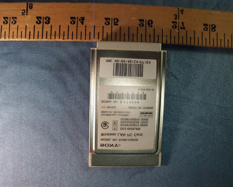
Click to zoom
Application Details
- Equipment Class
- DTS - Digital Transmission System
- Date of Grant
- Jan 29, 2004
- Application Purpose
- Original Equipment
- Date of Application
- Nov 30, 2003
- Equipment Note
- Wireless LAN PC Card
- Frequency Range
- 2412.00000000 - 2462.00000000
- Company
- Sony Group Corporation
- Country
- Japan
Documents & Files
Document Text
Text extracted from the exhibit documents filed with the FCC. Open a document above to read the original.
Users Manual
4Click the button that corresponds to your type of CD-ROM drive. If you are using an external CD-ROM drive, follow the instructions on the screen and copy the contents of the CD-ROM to your hard disk. When the copy is complete, click “Main Menu”. The Main Menu of the Easy Installation Wizard appears. 5Click “Install Driver”. 6When prompted, insert the Wireless LAN PC Card in the PC card slot. You do not need to turn off your computer when you insert the Wireless LAN PC Card. Notes • If your computer has two PC Card slots, insert the Wireless LAN PC Card into the top slot. If inserted into the bottom slot, the antenna of the Wireless LAN PC Card will block the top slot. • Depending on the depth and configuration of PC card slots on your computer, you may not be able to insert the Wireless LAN PC Card. Push the Wireless LAN PC Card into the slot until it is firmly seated. If the card does not fit easily, do not force it in. Take the card out and try reinserting it. When you insert the Wireless LAN PC Card, the device driver installed automatically. Wait until the installation is complete. 7When installation is complete, the following screen appears. Click “Continue”. Continuing allows you to install the utility software. 8Click “Install Software Utility”. The utility installation starts. Overview Important Computer Firewall Functions When using the Windows XP “Internet Connection Firewall” function Enabling the Windows XP “Internet Connection Firewall” function may prevent you from being able to access your computer through wireless communication. (This function is inactive under the Windows XP operating system default settings.) Because of this function, you may not be able to connect to your network when you change your Access Point settings. If this happens, deactivate the “Internet Connection Firewall” function, connect to the network, and then reactivate the function. For details, refer to Windows XP Help. Notes Network security is an important issue. You are urged to consider carefully how best to protect your computer. When using a personal firewall function provided by virus scanning or network security software Virus scanning and network security software sometimes includes a function called a “personal firewall” that is designed to prevent illegal access by outside entities. Depending on the software, the security level of this function may be initially set to a high level. If this high security level setting is left in effect, it may be impossible for an outside entity to access your computer. This can cause problems such as not being able to connect to the network when changing the Access Point’s settings. In this event, lower the security level in order to permit the network connection. For details, refer to the manuals provided with your software. Notes • Pay special attention to security issues. • For questions regarding firewall functions, please contact your firewall software manufacturer. 1When using the Wireless LAN PC Card in Access Point Network Connection mode, turn on the Access Point. zHint The Access Point Network connection mode is used when building a network around an access point (sold separately). The Peer to Peer Network connection mode is used when a network is composed mainly of computers with wireless capabilities (i.e. that do not need to connect through an access point). 2Insert the supplied CD-ROM into the CD-ROM drive of your computer. The Easy Installation Wizard starts automatically. zHint If the Easy Installation Wizard does not appear when you insert the supplied CD-ROM into your CD-ROM drive, double-click “Setup.exe” () on the CD-ROM. Depending on the settings of your computer, the file name may be “Setup”. 3When the following message appears, click “OK”. To remove the Wireless LAN PC Card 1Quit any software accessing the wireless LAN (e.g. Internet Explorer). 2Clickon your Windows operating system taskbar. 3Click “Safely remove Sony 802.11g Wireless LAN Adapter” or “Stop Sony 802.11g Wireless LAN Adapter” on the shortcut menu that appears. If your computer has two PC Card slots • When using a computer which has two PC Card slots arranged vertically (one above the other), insert the Wireless LAN PC Card into the top slot. If inserted into the bottom slot, the antenna of the Wireless LAN PC Card will block the top slot. • If you insert the Wireless LAN PC Card into a slot other than the one you usually use, the computer treats the card as a new device and automatically begins installing device drivers for it. Completing the driver installation makes it possible to use the Wireless LAN PC Card in that slot. Installation is performed automatically by the installation wizard. (For instructions on how to uninstall the Wireless LAN PC Card driver, see page 50.) zHint If you are using the Windows Me or Windows 2000 operating system, you can register up to 32 networks for each PC card slot. However, you have to register each network individually. You cannot share the settings across slots. To PC Card slot Insert in arrow direction The Wireless LAN PC Card (2.4 GHz/5 GHz IEEE 802.11a/b/g) PCWA-C800S is a PC Card type wireless network card. With this card, you can build a wireless LAN. This guide explains how to use the supplied CD-ROM to install the Wireless LAN PC Card device driver and Wireless Panel. You must insert the Wireless LAN PC Card into your computer before installing the device driver and Wireless Panel. 1Installing the software 4-679-929-11(1) PCWA-C800S © 2003 Sony Corporation Printed in Japan Wireless LAN PC Card (2.4 GHz/5 GHz IEEE 802.11a/b/g ) Quick Start Guide Before reading this guide, be sure to read the “Read This First” supplement. This guide explains how to install the software required to use of the Wireless LAN PC Card (2.4 GHz/5 GHz IEEE 802.11a/ b/g ) PCWA-C800S and the necessary settings to establish a connection with Access Point. Step 1Making Access Point The installation procedures are performed with an easy-to-use wizard. …
Text truncated - open the document above for the full version.
Cover Letter(s)
To: Bette Taube FCC [email protected] From: Helen Zhao Compliance Certification Services [email protected] Sent: Tuesday, December 02, 2003 4:00 PM Subject: Change of document lists that request confidentiality Dear Betty, We did FCC submission (composite device) yesterday for the following application: Applicant: Sony Corporation FCC ID: AK8PCWAC800S Confirmation #: EA400106 (DTS) Confirmation #: EA655154 (UNII) During the submission, only "Block Diagram", "Schematics", and "Theory of Operation" were checked as confidential, however today the client decided to include "Antenna Specification" in their Request for Confidentiality letter. Attached please find the file. Please kindly help us to update the filing in FCC database accordingly. I will upload this letter along with Request for Confidentiality letter to FCC today. Thank you! Helen
ID Label/Location Info
FCC ID LABEL LOCATION
RF Exposure Info
in accordance with the requirements of FCC Report and Order: ET Docket 93-62, and OET Bulletin 65 Supplement C for 802.11a/b/g Dual-Band Wireless LAN PCMCIA Card with Laptop Computers Host # 1: Sony, dynabook E7/518CME Host # 2: Sony, PCG-91L Host # 3: Sony, PCG661L Model: PCWA-C800S FCC ID: AK8PCWAC800S December 8, 2003 REPORT NO: 03I2353-3 Prepared for SONY Corporation 6-7-35 Kitasahinawa Shinagawa-Ku Tokyo Prepared by COMPLIANCE CERTIFICATION SERVICES 561F MONTEREY ROAD MORGAN HILL, CA 95037 USA TEL: (408) 463-0885 REPORT NO: 03I2353-3 DATE: December 8, 2003 FCC ID: AK8PCWAC800S COMPLIANCE CERTIFICATION SERVICES Page: 2 of 29 This report shall not be reproduced except in full, without the written approval of CCS. This document may be altered or revised by Compliance Certification Services personnel only, and shall be noted in the revision section of the document. CERTIFICATE OF COMPLIANCE (SAR EVALUATION) Dates of Tests: December 6 & 8, 2003 APPLICANT: SONY Corporation ADDRESS: 6-7-35 Kitasahinawa Shinagawa-Ku Tokyo BRAND/MODEL NAME: SONY / PCWA-C800S FCC ID: AK8PCWAC800S DEVICE CATEGORY: PORTABLE DEVICES EXPOSURE CATEGORY: GENERAL POPULATION/UNCONTROLLED EXPOSURE Test Sample is a: Production unit Modulation type: 802.11b Direct Sequence Spread Spectrum (DSSS) 802.11g Orthogonal Frequency Division Multiplexing (OFDM) Tx Frequency: 2412 MHz to 2462 MHz Max. O/P Power: (Conducted/Average) 14.79 dBm (DSSS) 14.72 dBm (OFDM) Max. SAR (1g): Host # 1: 0.382 mW/g Host # 2: 0.309 mW/g Host # 3: 0.234 mW/g Application Type: Certification FCC Rule Part(s): 15E Host devices: Host # 1: Sony, model dynabook E7/518CME Host # 2: Sony, model PCG-91L Host # 3: Sony, model PCG661L Note: This Report is only applicable for 802.11b/g This wireless portable device has been shown to be capable of compliance for localized specific absorption rate (SAR) for uncontrolled environment/general population exposure limits specified in ANSI/IEEE Std. C95.1-1992 and had been tested in accordance with the measurement procedures specified in FCC OET 65 Supplement C (released on 6/29/2001 see Test Report). I attest to the accuracy of data. All measurements reported herein were performed by me or were made under my supervision and are correct to the best of my knowledge and belief. I assume full responsibility for the completeness of these measurements and vouch for the qualifications of all persons taking them. Steve Cheng EMC Engineering Manager REPORT NO: 03I2353-3 DATE: December 8, 2003 FCC ID: AK8PCWAC800S COMPLIANCE CERTIFICATION SERVICES Page: 3 of 29 This report shall not be reproduced except in full, without the written approval of CCS. This document may be altered or revised by Compliance Certification Services personnel only, and shall be noted in the revision section of the document. TABLE OF CONTENTS 1. EQUIPMENT UNDER TEST (EUT) DESCRIPTION...........................................................4 2. REQUIREMENTS FOR COMPLIANCE TESTING DEFINED BY THE FCC...............................4 3. DOSIMETRIC ASSESSMENT SYSTEM..........................................................................4 3.1. MEASUREMENT SYSTEM DIAGRAM.....................................................................................................5 3.2. SYSTEM COMPONENTS......................................................................................................................6 4. EVALUATION PROCEDURES.....................................................................................8 5. MEASUREMENT UNCERTAINTY...............................................................................11 6. EXPOSURE LIMIT..................................................................................................12 7. MEASUREMENT RESULTS......................................................................................13 7.1. SIMULATING LIQUIDS PARAMETER CHECK.........................................................................................13 7.2. SYSTEM PERFORMANCE CHECK.......................................................................................................15 7.3. SAR MEASUREMENTS RESULTS.......................................................................................................17 7.4. PHOTOS .........................................................................................................................................23 8. EQUIPMENT LIST & CALIBRATION STATUS...............................................................27 9. REFERENCES......................................................................................................28 10. ATTACHMENTS....................................................................................................29 REPORT NO: 03I2353-3 DATE: December 8, 2003 FCC ID: AK8PCWAC800S COMPLIANCE CERTIFICATION SERVICES Page: 4 of 29 This report shall not be reproduced except in full, without the written approval of CCS. This document may be altered or revised by Compliance Certification Services personnel only, and shall be noted in the revision section of the document. 1. EQUIPMENT UNDER TEST (EUT) DESCRIPTION The following is the information provided by the applicant. Type of EUT: 802.11a/b/g Dual-Band Wireless LAN PCMCIA Card tested with the following host devices: Host # 1: Sony, model dynabook E7/518CME Host # 2: Sony, model PCG-91L Host # 3: Sony, model PCG661L Type/Model No.: PCWA-C800S Modulation Type: Direct Sequence Spread Spectrum (DSSS) Orthogonal Frequency Division Multiplexing (OFDM) TX Frequency: 2412 MHz to 2462 MHz Power Supply: Power supplied through the laptop computer 2. REQUIREMENTS FOR COMPLIANCE TESTING DEFINED BY THE FCC The US Federal Communications Commission has released the report and order “Guidelines for Evaluating the Environmental Effects of RF Radiation", ET Docket No. 93-62 in August 1996 [1]. The order requires routine SAR evaluation prior to equipment authorization of portable transmitter devices, including portable …
Text truncated - open the document above for the full version.
RF Exposure Info
Date/Time: 12/06/03 21:56:12 Test Laboratory: Compliance Certification Services D2450V2SN706_Probe 3021_120603 DUT: Dipole 2450 MHz; Type: D2450V2; Serial: D2450V2 - SN:706 Program Name: System Performance Check at 2450 MHz Ambient Temperature: 24.5 deg C; Liquid Temperature: 23.0 deg C Communication System: CW - 2450 MHz; Frequency: 2450 MHz;Duty Cycle: 1:1 Medium: Head 2450 MHz (σ = 1.8761 mho/m, ε r = 40.5891, ρ = 1000 kg/m 3 ) Phantom section: Flat Section DASY4 Configuration: z Probe: ES3DV2 - SN3021; ConvF(4.5, 4.5, 4.5); Calibrated: 7/29/2003 z Sensor-Surface: 4mm (Mechanical Surface Detection) z Electronics: DAE3 Sn427; Calibrated: 2/4/2003 z Phantom: SAM 1; Type: SAM 1; Serial: 1185 z Measurement SW: DASY4, V4.1 Build 47; Postprocessing SW: SEMCAD, V1.8 Build 62 d=10mm, Pin=250mW/Area Scan (7x7x1): Measurement grid: dx=15mm, dy=15mm Reference Value = 90.4 V/m Power Drift = 0.1 dB Maximum value of SAR = 14.5 mW/g d=10mm, Pin=250mW/Zoom Scan (5x5x7)/Cube 0: Measurement grid: dx=7.5mm, dy=7.5mm, dz=5mm Peak SAR (extrapolated) = 29.0 W/kg SAR(1 g) = 13.2 mW/g; SAR(10 g) = 6.23 mW/g Reference Value = 90.4 V/m Power Drift = 0.1 dB Maximum value of SAR = 14.8 mW/g 0 dB = 15.3mW/g Date/Time: 12/06/03 21:56:12 Test Laboratory: Compliance Certification Services D2450V2SN706_Probe 3021_120603 DUT: Dipole 2450 MHz; Type: D2450V2; Serial: D2450V2 - SN:706 DASY4 Configuration: z Probe: ES3DV2 - SN3021; ConvF(4.5, 4.5, 4.5); Calibrated: 7/29/2003 z Sensor-Surface: 0mm (Fix Surface) z Electronics: DAE3 Sn427; Calibrated: 2/4/2003 z Phantom: SAM 1; Type: SAM 1; Serial: 1185 z Measurement SW: DASY4, V4.1 Build 47; Postprocessing SW: SEMCAD, V1.8 Build 62 d=10mm, Pin=250mW/Z Scan (1x1x51): Measurement grid: dx=20mm, dy=20mm, dz=2mm Reference Value = 90.4 V/m Power Drift = 0.1 dB Maximum value of SAR = 21.9 mW/g Date/Time: 12/08/03 11:28:56 Test Laboratory: Compliance Certification Services D2450V2SN706_Probe 3021_120803 DUT: Dipole 2450 MHz; Type: D2450V2; Serial: D2450V2 - SN:706 Program Name: System Performance Check at 2450 MHz Ambient Temperature: 24.5 deg C; Liquid Temperature: 23.0 deg C Communication System: CW - 2450 MHz; Frequency: 2450 MHz;Duty Cycle: 1:1 Medium: Head 2450 MHz (σ = 1.7981 mho/m, ε r = 40.2697, ρ = 1000 kg/m 3 ) Phantom section: Flat Section DASY4 Configuration: z Probe: ES3DV2 - SN3021; ConvF(4.5, 4.5, 4.5); Calibrated: 7/29/2003 z Sensor-Surface: 4mm (Mechanical Surface Detection) z Electronics: DAE3 Sn427; Calibrated: 2/4/2003 z Phantom: SAM 1; Type: SAM 1; Serial: 1185 z Measurement SW: DASY4, V4.1 Build 47; Postprocessing SW: SEMCAD, V1.8 Build 62 d=10mm, Pin=250mW/Area Scan (7x7x1): Measurement grid: dx=15mm, dy=15mm Reference Value = 89.2 V/m Power Drift = 0.0 dB Maximum value of SAR = 14.7 mW/g d=10mm, Pin=250mW/Zoom Scan (5x5x7)/Cube 0: Measurement grid: dx=7.5mm, dy=7.5mm, dz=5mm Peak SAR (extrapolated) = 27.7 W/kg SAR(1 g) = 12.9 mW/g; SAR(10 g) = 5.57 mW/g Reference Value = 89.2 V/m Power Drift = 0.0 dB Maximum value of SAR = 14.8 mW/g 0 dB = 13.8mW/g Date/Time: 12/08/03 11:28:56 Test Laboratory: Compliance Certification Services D2450V2SN706_Probe 3021_120803 DUT: Dipole 2450 MHz; Type: D2450V2; Serial: D2450V2 - SN:706 DASY4 Configuration: z Probe: ES3DV2 - SN3021; ConvF(4.5, 4.5, 4.5); Calibrated: 7/29/2003 z Sensor-Surface: 0mm (Fix Surface) z Electronics: DAE3 Sn427; Calibrated: 2/4/2003 z Phantom: SAM 1; Type: SAM 1; Serial: 1185 z Measurement SW: DASY4, V4.1 Build 47; Postprocessing SW: SEMCAD, V1.8 Build 62 d=10mm, Pin=250mW/Z Scan (1x1x51): Measurement grid: dx=20mm, dy=20mm, dz=2mm Reference Value = 89.2 V/m Power Drift = 0.0 dB Maximum value of SAR = 21.7 mW/g
RF Exposure Info
Date/Time: 12/07/03 01:56:06 Test Laboratory: Compliance Certification Services EUT Setup Configuration 1_Host # 1 DUT: Sony Corporation; Type: PCWA-C800S; Serial: N/A Program Name: EUT Setup Configuration 1 Ambient Temperature: 24.5 deg C; Liquid Temperature: 23.0 deg C Communication System: DSSS; Frequency: 2412 MHz;Duty Cycle: 1:1.11 Medium: Muscle 2450 MHz (σ = 2.0165 mho/m, ε r = 52.3478, ρ = 1000 kg/m 3 ) Phantom section: Flat Section DASY4 Configuration: z Probe: ES3DV2 - SN3021; ConvF(4.1, 4.1, 4.1); Calibrated: 7/29/2003 z Sensor-Surface: 4mm (Mechanical Surface Detection) z Electronics: DAE3 Sn427; Calibrated: 2/4/2003 z Phantom: SAM 2; Type: SAM 2; Serial: 1050 z Measurement SW: DASY4, V4.1 Build 47; Postprocessing SW: SEMCAD, V1.8 Build 62 Low Channel/Area Scan (7x11x1): Measurement grid: dx=15mm, dy=15mm Reference Value = 10.4 V/m Power Drift = 0.0 dB Maximum value of SAR = 0.195 mW/g Low Channel/Zoom Scan (5x5x7)/Cube 0: Measurement grid: dx=7.5mm, dy=7.5mm, dz=5mm Peak SAR (extrapolated) = 0.420 W/kg SAR(1 g) = 0.217 mW/g; SAR(10 g) = 0.111 mW/g Reference Value = 10.4 V/m Power Drift = 0.0 dB Maximum value of SAR = 0.237 mW/g 0 dB = 0.237mW/g Date/Time: 12/07/03 01:56:06 Test Laboratory: Compliance Certification Services EUT Setup Configuration 1_Host # 1 DUT: Sony Corporation; Type: PCWA-C800S; Serial: N/A Program Name: EUT Setup Configuration 1 Ambient Temperature: 24.5 deg C; Liquid Temperature: 23.0 deg C Communication System: DSSS; Frequency: 2437 MHz;Duty Cycle: 1:1.11 Medium: Muscle 2450 MHz (σ = 2.0165 mho/m, ε r = 52.3478, ρ = 1000 kg/m 3 ) Phantom section: Flat Section DASY4 Configuration: z Probe: ES3DV2 - SN3021; ConvF(4.1, 4.1, 4.1); Calibrated: 7/29/2003 z Sensor-Surface: 4mm (Mechanical Surface Detection) z Electronics: DAE3 Sn427; Calibrated: 2/4/2003 z Phantom: SAM 2; Type: SAM 2; Serial: 1050 z Measurement SW: DASY4, V4.1 Build 47; Postprocessing SW: SEMCAD, V1.8 Build 62 Middle Channel/Area Scan (7x11x1): Measurement grid: dx=15mm, dy=15mm Reference Value = 12.6 V/m Power Drift = 0.0 dB Maximum value of SAR = 0.308 mW/g Middle Channel/Zoom Scan (5x5x7)/Cube 0: Measurement grid: dx=7.5mm, dy=7.5mm, dz=5mm Peak SAR (extrapolated) = 0.673 W/kg SAR(1 g) = 0.343 mW/g; SAR(10 g) = 0.168 mW/g Reference Value = 12.6 V/m Power Drift = 0.0 dB Maximum value of SAR = 0.387 mW/g Date/Time: 12/07/03 01:56:06 Test Laboratory: Compliance Certification Services EUT Setup Configuration 1_Host # 1 DUT: Sony Corporation; Type: PCWA-C800S; Serial: N/A DASY4 Configuration: z Probe: ES3DV2 - SN3021; ConvF(4.1, 4.1, 4.1); Calibrated: 7/29/2003 z Sensor-Surface: 0mm (Fix Surface) z Electronics: DAE3 Sn427; Calibrated: 2/4/2003 z Phantom: SAM 2; Type: SAM 2; Serial: 1050 z Measurement SW: DASY4, V4.1 Build 47; Postprocessing SW: SEMCAD, V1.8 Build 62 Middle Channel/Z Scan (1x1x51): Measurement grid: dx=20mm, dy=20mm, dz=2mm Reference Value = 12.6 V/m Power Drift = -0.0 dB Maximum value of SAR = 0.275 mW/g Date/Time: 12/07/03 01:56:06 Test Laboratory: Compliance Certification Services EUT Setup Configuration 1_Host # 1 DUT: Sony Corporation; Type: PCWA-C800S; Serial: N/A Program Name: EUT Setup Configuration 1 Ambient Temperature: 24.5 deg C; Liquid Temperature: 23.0 deg C Communication System: DSSS; Frequency: 2462 MHz;Duty Cycle: 1:1.11 Medium: Muscle 2450 MHz (σ = 2.0165 mho/m, ε r = 52.3478, ρ = 1000 kg/m 3 ) Phantom section: Flat Section DASY4 Configuration: z Probe: ES3DV2 - SN3021; ConvF(4.1, 4.1, 4.1); Calibrated: 7/29/2003 z Sensor-Surface: 4mm (Mechanical Surface Detection) z Electronics: DAE3 Sn427; Calibrated: 2/4/2003 z Phantom: SAM 2; Type: SAM 2; Serial: 1050 z Measurement SW: DASY4, V4.1 Build 47; Postprocessing SW: SEMCAD, V1.8 Build 62 High Channel/Area Scan (7x11x1): Measurement grid: dx=15mm, dy=15mm Reference Value = 10 V/m Power Drift = 0.1 dB Maximum value of SAR = 0.221 mW/g High Channel/Zoom Scan (5x5x7)/Cube 0: Measurement grid: dx=7.5mm, dy=7.5mm, dz=5mm Peak SAR (extrapolated) = 0.443 W/kg SAR(1 g) = 0.223 mW/g; SAR(10 g) = 0.108 mW/g Reference Value = 10 V/m Power Drift = 0.1 dB Maximum value of SAR = 0.242 mW/g Date/Time: 12/07/03 01:56:06 Test Laboratory: Compliance Certification Services EUT Setup Configuration 1_Host # 1 DUT: Sony Corporation; Type: PCWA-C800S; Serial: N/A Program Name: EUT Setup Configuration 1 Ambient Temperature: 24.5 deg C; Liquid Temperature: 23.0 deg C Communication System: DSSS; 802.11g mode, Frequency: 2412 MHz;Duty Cycle: 1:1.11 Medium: Muscle 2450 MHz (σ = 2.0165 mho/m, ε r = 52.3478, ρ = 1000 kg/m 3 ) Phantom section: Flat Section DASY4 Configuration: z Probe: ES3DV2 - SN3021; ConvF(4.1, 4.1, 4.1); Calibrated: 7/29/2003 z Sensor-Surface: 4mm (Mechanical Surface Detection) z Electronics: DAE3 Sn427; Calibrated: 2/4/2003 z Phantom: SAM 2; Type: SAM 2; Serial: 1050 z Measurement SW: DASY4, V4.1 Build 47; Postprocessing SW: SEMCAD, V1.8 Build 62 Low Channel 2/Area Scan (7x11x1): Measurement grid: dx=15mm, dy=15mm Reference Value = 10.4 V/m Power Drift = -0.1 dB Maximum value of SAR = 0.197 mW/g Low Channel 2/Zoom Scan (5x5x7)/Cube 0: Measurement grid: dx=7.5mm, dy=7.5mm, dz=5mm Peak SAR (extrapolated) = 0.405 W/kg SAR(1 g) = 0.209 mW/g; SAR(10 g) = 0.107 mW/g Reference Value = 10.4 V/m Power Drift = -0.1 dB Maximum value of SAR = 0.226 mW/g Date/Time: 12/07/03 01:56:06 Test Laboratory: Compliance Certification Services EUT Setup Configuration 1_Host # 1 DUT: Sony Corporation; Type: PCWA-C800S; Serial: N/A Program Name: EUT Setup Configuration 1 Ambient Temperature: 24.5 deg C; Liquid Temperature: 23.0 deg C Communication System: DSSS; 802.11g mode, Frequency: 2437 MHz;Duty Cycle: 1:1.11 Medium: Muscle 2450 MHz (σ = 2.0165 mho/m, ε r = 52.3478, ρ = 1000 kg/m 3 ) Phantom section: Flat Section DASY4 Configuration: z Probe: ES3DV2 - SN3021; ConvF(4.1, 4.1, 4.1); Calibrated: 7/29/2003 z Sensor-Surface: 4mm (Mechanical Surface Detection) z Electronics: DAE3 Sn427; Calibrated: 2/4/2003 z Phantom: SAM 2; Type: SAM 2; Serial: 1050 z …
Text truncated - open the document above for the full version.
Test Report
FCC CFR47 PART 15 SUBPART C CERTIFICATION TEST REPORT FOR EUT: WIRELESS LAN PC CARD MODEL NUMBER: PCWA-C800S FCC ID: AK8PCWAC800S REPORT NUMBER: 03I2353-1 ISSUE DATE: NOVEMBER 26, 2003 Prepared for SONY CORPORATION 6-7-35 KITASHINAGAWA SHINAGAWA-KU TOKYO, 141-0001 JAPAN Prepared by COMPLIANCE CERTIFICATION SERVICES 561F MONTEREY ROAD, MORGAN HILL, CA 95037, USA TEL: (408) 463-0885 FAX: (408) 463-0888 REPORT NO: 03I2353-1 DATE: NOVEMBER 26, 2003 EUT: WIRELESS LAN PC CARD FCC ID: AK8PCWAC800S Page 2 of 96 COMPLIANCE CERTIFICATION SERVICES DOCUMENT NO: CCSUP4031A 561F MONTEREY ROAD, MORGAN HILL, CA 95037 USA TEL: (408) 463-0885 FAX: (408) 463-0888 This report shall not be reproduced except in full, without the written approval of CCS. This document may be altered or revised by Compliance Certification Services personnel only, and shall be noted in the revision section of the document. TABLE OF CONTENTS 1. TEST RESULT CERTIFICATION.................................................................................................3 2. EUT: WIRELESS LAN PC CARD DESCRIPTION......................................................................4 3. TEST METHODOLOGY..................................................................................................................5 4. FACILITIES AND ACCREDITATION..........................................................................................5 5. CALIBRATION AND UNCERTAINTY.........................................................................................6 5.1. MEASURING INSTRUMENT CALIBRATION............................................................................6 5.2. MEASUREMENT UNCERTAINTY..............................................................................................6 5.3. TEST AND MEASUREMENT EQUIPMENT...............................................................................7 6. SETUP OF EQUIPMENT UNDER TEST.......................................................................................8 7. APPLICABLE LIMITS AND TEST RESULTS...........................................................................10 7.1. 6 dB BANDWIDTH.....................................................................................................................10 7.2. 99% BANDWIDTH.....................................................................................................................18 7.3. PEAK OUTPUT POWER...........................................................................................................26 7.4. MAXIMUM PERMISSIBLE EXPOSURE...................................................................................35 7.5. AVERAGE POWER....................................................................................................................38 7.6. PEAK POWER SPECTRAL DENSITY.......................................................................................39 7.7. CONDUCTED SPURIOUS EMISSIONS...................................................................................47 7.8. RADIATED EMISSIONS............................................................................................................62 7.8.1. TRANSMITTER RADIATED SPURIOUS EMISSIONS................................................62 7.8.2. TRANSMITTER RADIATED EMISSIONS ABOVE 1 GHZ..........................................65 7.8.3. WORST-CASE RADIATED EMISSIONS BELOW 1 GHZ............................................84 7.9. POWERLINE CONDUCTED EMISSIONS................................................................................88 8. SETUP PHOTOS..............................................................................................................................92 REPORT NO: 03I2353-1 DATE: NOVEMBER 26, 2003 EUT: WIRELESS LAN PC CARD FCC ID: AK8PCWAC800S Page 3 of 96 COMPLIANCE CERTIFICATION SERVICES DOCUMENT NO: CCSUP4031A 561F MONTEREY ROAD, MORGAN HILL, CA 95037 USA TEL: (408) 463-0885 FAX: (408) 463-0888 This report shall not be reproduced except in full, without the written approval of CCS. This document may be altered or revised by Compliance Certification Services personnel only, and shall be noted in the revision section of the document. 1. TEST RESULT CERTIFICATION COMPANY NAME: SONY CORPORATION 6-7-35 KITASHINAGAWA SHINAGAWA-KU TOKYO, 141-0001 JAPAN EUT: WIRELESS LAN PC CARD DESCRIPTION MODEL: PCWA-C800S DATE TESTED: NOVEMBER 18 – 26, 2003 APPLICABLE STANDARDS STANDARD TEST RESULTS FCC PART 15 SUBPART C NO NON-COMPLIANCE NOTED Compliance Certification Services, Inc. tested the above equipment in accordance with the requirements set forth in the above standards. The test results show that the equipment tested is capable of demonstrating compliance with the requirements as documented in this report. Note: This document reports conditions under which testing was conducted and results of tests performed. This document may not be altered or revised in any way unless done so by Compliance Certification Services and all revisions are duly noted in the revisions section. Any alteration of this document not carried out by Compliance Certification Services will constitute fraud and shall nullify the document. Note: The 2.4 GHz band is applicable to this report; another band of operation (5.2 GHz) is documented in a separate report. Approved & Released For CCS By: Tested By: MIKE HECKROTTE THANH NGUYEN CHIEF ENGINEER EMC TECHNICIAN COMPLIANCE CERTIFICATION SERVICES COMPLIANCE CERTIFICATION SERVICES REPORT NO: 03I2353-1 DATE: NOVEMBER 26, 2003 EUT: WIRELESS LAN PC CARD FCC ID: AK8PCWAC800S Page 4 of 96 COMPLIANCE CERTIFICATION SERVICES DOCUMENT NO: CCSUP4031A 561F MONTEREY ROAD, MORGAN HILL, CA 95037 USA TEL: (408) 463-0885 FAX: (408) 463-0888 This report shall not be reproduced except in full, without the written approval of CCS. This document may be altered or revised by Compliance Certification Services personnel only, and shall be noted in the revision section of the document. 2. EUT: WIRELESS LAN PC CARD DES…
Text truncated - open the document above for the full version.
Test Report
Peak/Average Output power re-measurement under same setup Plot 1_11a Mid channel 5260M Peak vs. Ave Plot 2_11a Turbo Mid channel 5250M Peak vs. Ave Plot 3_11b Mid channel 2437M Peak vs. Ave Plot 4_11g Mid channel 2437M Peak vs. Ave Plot 5_11g Turbo Mid channel 2437M Peak vs. Ave Plot 6_11a Mid channel 5260M Peak vs. Ave with Peak Detection without RMS pwer average.Ave Plot 7_Test setup
Test Setup Photos
REPORT NO: 03I2353-1 DATE: NOVEMBER 26, 2003 EUT: WIRELESS LAN PC CARD FCC ID: AK8PCWAC800S Page 92 of 96 COMPLIANCE CERTIFICATION SERVICES DOCUMENT NO: CCSUP4031A 561F MONTEREY ROAD, MORGAN HILL, CA 95037 USA TEL: (408) 463-0885 FAX: (408) 463-0888 This report shall not be reproduced except in full, without the written approval of CCS. This document may be altered or revised by Compliance Certification Services personnel only, and shall be noted in the revision section of the document. 8. SETUP PHOTOS ANTENNA PORT CONDUCTED RF MEASUREMENT SETUP ANTENNA PORT CONDUCTED PHOTO REPORT NO: 03I2353-1 DATE: NOVEMBER 26, 2003 EUT: WIRELESS LAN PC CARD FCC ID: AK8PCWAC800S Page 93 of 96 COMPLIANCE CERTIFICATION SERVICES DOCUMENT NO: CCSUP4031A 561F MONTEREY ROAD, MORGAN HILL, CA 95037 USA TEL: (408) 463-0885 FAX: (408) 463-0888 This report shall not be reproduced except in full, without the written approval of CCS. This document may be altered or revised by Compliance Certification Services personnel only, and shall be noted in the revision section of the document. RADIATE…
Text truncated - open the document above for the full version.
Contact Information
Applicant
Kazuyuki Hori(Chief EMC/RF Compliance Specialist)
Technical Contact
COMPLIANCE CERTIFICATION SERVICESSTEVE CHENG
[email protected]408-463-0885
561F MONTEREY ROAD · MORGAN HILL, California · United States
Test Firm
Compliance Certification Services IncSteve Cheng
Technical Specifications
| # | Rule Parts | Frequency Range | Power Output |
|---|---|---|---|
| 1 | 15C | 2.41 GHz - 2.46 GHz | 158.49 mW |
Other Applications from Sony Group Corporation
AK8WW81782
Aug 21, 2026Radio Equipment
Equipment Class
DSS - Part 15 Spread Spectrum TransmitterAK8CFIZCP2
Aug 03, 2026Wireless Controller
Equipment Class
DSS - Part 15 Spread Spectrum TransmitterAK8OEV321MUH
Apr 14, 2026LCD Monitor
Equipment Class
JAD - Part 15 Class A Digital DeviceAK8OEV431MUH
Apr 14, 2026LCD Monitor
Equipment Class
JAD - Part 15 Class A Digital DeviceAK8OEV271MUH
Apr 14, 2026LCD Monitor
Equipment Class
JAD - Part 15 Class A Digital Device