AK8PEGAWL110Compact Flash Wireless LAN Card
Sony Group Corporation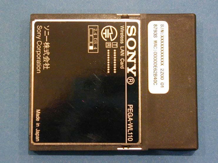
Click to zoom
Application Details
- Equipment Class
- DTS - Digital Transmission System
- Date of Grant
- Mar 25, 2003
- Application Purpose
- Original Equipment
- Date of Application
- Mar 25, 2003
- Equipment Note
- Compact Flash Wireless LAN Card
- Frequency Range
- 2412.00000000 - 2462.00000000
- Company
- Sony Group Corporation
- Country
- Japan
Documents & Files
Document Text
Text extracted from the exhibit documents filed with the FCC. Open a document above to read the original.
Users Manual
4-672-978-21 (1) Wireless LAN Card Operating Instructions Mode d’emploi 2003 Sony Corporation PEGA-WL110 US FR 2 US Owner’s Record The model number and serial number are located at the rear of the product. Record the model number and the serial number in the space provided below. Refer to them whenever you call upon your Sony dealer regarding this product. Model Number : PEGA-WL110 Serial Number : __________________ For customers in the U.S.A. and Canada : NOTICE This equipment has been tested and found to comply with the limits for a Class B digital device, pursuant to part 15 of the FCC Rules. These limits are designed to provide reasonable protection against harmful interference in a residential installation. This equipment generates, uses and can radiate radio frequency energy and, if not installed and used in accordance with the instructions, may cause harmful interference to radio communications. However, there is no guarantee that interference will not occur in a particular installation. If this equipment does cause harmful interference to radio or television reception, which can be determined by turning the equipment off and on, the user is encouraged to try to correct the interference by one or more of the following measures: —Change the direction and position of the receiving antenna. —Increase the distance between the equipment and receiver. —Connect the equipment into an outlet on a circuit different from that to which the receiver is connected. —Consult the dealer or an experienced radio/TV technician for help. FCC WARNING Changes or modifications not expressly approved by the party responsible for compliance could void the user’s authority to operate the equipment. 3 US Declaration of Conformity Trade Name: SONY Model No.: PEGA-WL110 Responsible Party : Sony Electronics Inc. Address: 680 Kinderkamack Road, Oradell, NJ 07649 USA Telephone No.: 201-930-6972 This device complies with part 15 of the FCC Rules. Operation is subject to the following two conditions: (1) This device may not cause harmful interference, and (2) this device must accept any interference received, including interference that may cause undesired operation. FCC Radiation Exposure Statement: The available scientific evidence does not show that any health problems are associated with using low power wireless devices. There is no proof, however, that these low power wireless devices are absolutely safe. Low power Wireless devices emit low levels of radio frequency energy (RF) in the microwave range while being used. Whereas high levels of RF can produce health effects (by heating tissue), exposure to low level RF that does not produce heating effects causes no known adverse health effects. Many studies of low level RF exposures have not found any biological effects. Some studies have suggested that some biological effects might occur, but such findings have not been confirmed by additional research. The Wireless LAN Card (PEGA-WL110) has been tested and found to comply with the Federal Communications Commission (FCC) guidelines on radio frequency energy (RF) exposures. The maximum SAR levels tested for the Wireless LAN Card (PEGA-WL110) has been shown to be 0.962 W/kg at body. The term “IC:” before the radio certification number only signifies that Industry Canada technical specifications were met. Operation is subject to the following two conditions: (1) this device may not cause interference, and (2) this device must accept any interference, including interference that may cause undesired operation of the device. Continued on next page US 4 US To prevent radio interference to the licensed service, this device is intended to be operated indoors and away from windows to provide maximum shielding. Equipment (or its transmit antenna) that is installed outdoors is subject to licensing. IC Exposure of Humans to RF Fields The installer of this radio equipment must ensure that the antenna is located or pointed such that it does not emit RF field in excess of Health Canada limits for the general population; consult Safety Code 6, obtainable from Health Canada’s website:www.hc-sc.gc.ca/rpb This Class B digital apparatus complies with Canadian ICES-003. For customers in European Countries: Sony Corporation hereby declares that this Wireless LAN Card is in compliance with the essential requirements and other relevant provisions of the European Directive 1999/5/EC (R&TTE). To obtain a copy of the Declaration of Conformity (DoC) with the R&TTE Directive, please access the following URL address: http://www.compliance.sony.de In some countries the use of the Wireless LAN Card is restricted. Before using it, make sure you read the Wireless LAN Regulations leaflet of this product. Warnings •In some situations or environments, the use of the IEEE 802.11b technology might be restricted by the proprietor of the building or responsible representatives of the organization, for example on board of airplanes, in hospitals or in any other environment where the risk of interference with other devices or services is perceived or identified as harmful. •If you are uncertain about the policy applying to the use of IEEE 802.11b technology in a specific organization or environment, you are encouraged to first ask for authorization prior to switching it on. •Consult your physician or the manufacturer of personal medical devices (pacemakers, hearing aids, etc.) regarding any restrictions on the use of IEEE 802.11b technology. 5 US •Sony, , CLIÉ, , CLIÉ GEAR, , , Jog Dial and Memory Stick are trademarks of Sony Corporation. •Palm OS and HotSync are registered trademarks of Palm, Inc. or its subsidiaries. Palm Desktop and HotSync logo are trademarks of Palm, Inc. or its subsidiaries. •Microsoft, Windows and Windows NT are registered trademarks of Microsoft Corporation in the United States and/or other countries. •Adobe and Adobe Acrobat Reader are trademarks of Adobe Systems Incorporated. •All other names of systems, products and services …
Text truncated - open the document above for the full version.
Cover Letter(s)
American Telecommunications Certification Body Inc. 6731 Whittier Ave, McLean, VA 22101 March 11, 2003 RE: FCC ID: AK8PEGAWL110_ATCB000278 Attention: Keijiro Kumagai / Hiroka Umeyama I have a few comments on this Application. 1. The Form Factor has not been clearly identified. IT appears to be PCMCIA. Please disclose the correct form factor for this device. 2. Even though the device was tested stand alone using a laptop, the device appears to be primarily for PDA use. This then brings the question as to the applicability of the EMC as well as the SAR testing performed. The manufacturer states the intent of this device is for use in a PDA. As well. Consequently, while there are PCMCIA ‘adapters’ commonly available and while the device may be purchased and used in this adapter, since the intent of this device is for PDA also, this is how the SAR should also have been tested in test setup measurements 1, 2 and 3. Please explain why a PDA configuration was not used. 3. Your manual reports only Body SAR. It appears that this device can and will find its way into PDAs that may have or will have cell phone type uses. This means that they will be used next to the head. What steps have you taken to test the product in this obvious use situation? Alternately, since this device will be sold to stores that market the device for use with and in the adapters listed in item 1 and since this device as sold, can also be used in potential PDA situations as stated in this item, please explain how the manufacturer can make this device unusable in the PDA cell phone configuration (i.e. how can the manufacturer limit this device for use solely in Sony and other manufacturer PDAs not having only PCMCIA slot and not having cell phone capabilities?). 4. If this device can be used with a PDA that has cell phone capabilities and can transmit simultaneously with that transmitter, it may fall under the TCB exclusion list II(e) which states that “devices containing multiple transmitters that transmit simultaneously, when routine SAR evaluation is required for the highest output (dominant) transmitter, and any of the other (non- dominant) transmitters is operating at higher than 5 mW “ Please explain this possibility. 5. Normally, modules are used in specific configurations. This then means that the OEM must install the module. However, the manual clearly indicates that this device is meant to plug in and out of the PDA or notebook using the PCMCIA adapter by the end user. This is typically against the intent of the FCC classification of a module. PCMCIA type devices are not strictly classified as “modular” devices. This appears to be of the PCMCIA type classification (i.e. plugs into a ‘PCMCIA” external type card slot. How does the manufacturer prevent incorrect use of this device in the PDA? ( I.e. does the manufacturer only sell this to OEM and require OEM installation? If so, how does he control OEM use or resale in a ‘plug and play’ PDA/Cell phone or CFA form factor to PCMCIA adapter configuration). 6. Again, the SAR report states Notebook computer use, yet the manual specifically states PDA use. (While the SAR report correctly identified the Notebook use, the manufacturer incorrectly only identifies sole PDA use.) Please clarify. Dennis Ward mailto:[email protected] The items indicated above must be submitted before processing can continue on the above referenced application. Failure to provide the requested information may result in application termination. Correspondence should be considered part of the permanent submission and may be viewed from the Internet after a Grant of Equipment Authorization is issued. z Page 2 March 11, 2003 Please do not respond to this correspondence using the email reply button. In order for your response to be processed expeditiously, you must submit your documents through the AmericanTCB.com website. Also, please note that partial responses increase processing time and should not be submitted. Any questions about the content of this correspondence should be directed to the sender.
Cover Letter(s)
1 dward From: [email protected] Sent: Wednesday, March 19, 2003 4:53 AM To: [email protected]; [email protected] Cc: [email protected]; [email protected]; Bill Graff Subject: RE: New Project Wireless LAN Card(FCC ID:AK8PEGAWL110) Dear Dennis, I suppose there are slight difference of opinion between us about this matter. Anyway our customer is pushing us to obtain grant for this device everyday so we have to solve these problems as soon as possible. Please give us your immediate advice and help. 1. About EMC report Is there any problem with the report? 2. About SAR Report 1) We will conduct additional test with using PDA. 2) We will only test with one PDA, because the power of WLAN card is below 100mW. 3) We will test the device with body SAR measurement. The reasons are as follows. - While Card of GSM have possibility to use as cell phone, the WLAN card of 802.11b is not used for PDA as cell phone. - Please refer to the test report of "FCC ID: P4JDTE-3" on FCC web site. This device have GSM function, so there is no wonder if they apply Head SAR measurement. However, this test report does not include the result of Head SAR measurement. 3. Form Factor This card is CompactFlash Card and can be inserted into PCMCIA slot with using adapter. Mostly It can be inserted directly into PDA. So how can we explain about Form Factor, please give us advice. 4. Co-located (Co-operating) This is not applicable for WLAN card itself, testing is only required for PC or PDA which is using this WLAN card. Therefore, "must not be co-located or operating in conjunction" will be stated in grant as assumption of approval. I appreciate for your speedy response about this matter and I am looking forward to hearing from you. Best Regards, Keijiro Kumagai A-Pex International Co.Ltd. 4383-326 Asama-cho Ise-shi Mie-ken 516-0021 JAPAN TEL +81-596-24-8116 FAX +81-596-24-8124 E-mail: [email protected] 2003/03/15 6:19:48、"dward"さんは「RE: New Project Wireless LAN Card(FCC ID:AK8PEGAWL110)」で書きました > Hi Keijiro 2 > The 'form factor' in this situation is talking about the method used > to connect to another device and the size of the device. For example, > the card > can be plugged into an adapter which could then be plugged into a > normal PCMCAI slot. The connection between the card and the adapter > however, has > not been clearly identified. I cannot assume that it is a PCMCIA nor > can I > assume that it is not a mini/PCMCIA form factor. This information > needs to > be provided. > > For SAR, please note that the FCC is specifically concerned about > these new > type devices that can be used in cell phone PDA arrangements. Please note > that there are a number of PDA 'phones" that are used held to the head and > there is no indication that steps have been taken in the design of > this item > to prevent use in that situation. While the antenna(s) for these > devices may not be actually against the head, the manner in which > these phones are > held is in the typical cell phone position next to the head. Consequently, > body SAR is inappropriate for this type configuration. > > If you can show that the device could not be used in any currently available > PDA cell phone configurations, then you may only need to do body SAR > for the > PDA shown in the manual. However, simply stating that it is not recommended > is not enough. There must be methods in place to prevent such use. Since > it is highly unlikely that such use can be prevented and since SAR is very > dependent on the type device, SAR for the PDA will have to be done. > SAR in > the PDA Sony mentions can be done using Body SAR, however, again, > since this > device WILL find it way into a PDA cell phone, Sony needs to address > this issue as well (head SAR). > 3 > Also, please note that if the device can operate simultaneously with a PDA > cell phone, then the FCC may have to issue the grant in that scenario. > > Thanks > Dennis > > -----Original Message----- > From: [email protected] [mailto:[email protected]] > Sent: Friday, March 14, 2003 3:57 AM > To: [email protected]; [email protected] > Cc: [email protected]; [email protected] > Subject: RE: New Project Wireless LAN Card(FCC ID:AK8PEGAWL110) > > > > > Dear Dennis, > > Please check our reply for your comments. Please confirm. > > 1. I do not understand what "Form Factor" is? Please explain this > comment in more detail. > > 2. At the moment, this WLAN card is intended for PDA, however, for > expand the possibilities for PC, we conducted SAR testing with 3 PC. > We wanted to > test this device with PDA, however, for the licensing reason, we could not > set software for testing transmission for PDA. Because of that, we > tested this device with worst condition using extension board > additionally. Is it > acceptable? We are aware that if output power of the device is higher than > 100mW, we are required to test with using 3 host device. > > eg. make usable for PC and PDA --> We have to test with 3 of each host > device(PC1, PC2, PC3, PDA1, PDA2, PDA3). > > If a device is under 100mW, what do we do? Please inform us. > > eg. make usable for PC and PDA --> We need to test with only 1 of each host > device (PC1, PDA1). > > Am I correct about case of under 100mW? > > 3. We understand what you mean but we do not think most of PDA can > use as > cell phone with touching directly to face. So could we just use any > PDA 4 to > measure Head SAR with Body SAR position? > > 4. In our opinion, it is not a problem of LAN card itself, but it is a > problem for a device which use WLAN card. For LAN card we need to put > following statement in the manual. "This transmitter must not be > co-located with any other transmitter or antenna" > > 5. The answer for this comment contains in answer No.4 above. > > 6. The answer for this comment contains in answer No.2 above. > > Please confirm. > > > Best Regards, > > Keijiro Kumagai > A-Pex International Co.Ltd. > 4383-326 Asama-cho Ise-shi > Mie-ken 516-0021 J…
Text truncated - open the document above for the full version.
External Photos
External Photo Sony Corporation Model Name: PEGA-WL110 FCC ID: AK8PEGAWL110 Wireless LAN Card (Top) Wireless LAN Card (Bottom) External Photo Sony Corporation Model Name: PEGA-WL110 FCC ID: AK8PEGAWL110 Wireless LAN Card (Left) Wireless LAN Card (Right) External Photo Sony Corporation Model Name: PEGA-WL110 FCC ID: AK8PEGAWL110 Wireless LAN Card (Front) Wireless LAN Card (Back)
Internal Photos
Internal Photo Sony Corporation Model Name: PEGA-WL110 FCC ID: AK8PEGAWL110 Module-Top Module-Bottom with RF Shield Internal Photo Sony Corporation Model Name: PEGA-WL110 FCC ID: AK8PEGAWL110 Module-Bottom without RF Shield
Operational Description
Block Diagram description of PEGA-WL110 [Receiver path] The 2.4GHz RF signal enters via antenna (1) and band pass filter (2) the RF/IF converter ISL3685IR (3) to be converted to 374MHz IF. The 374MHz IF signal then goes through a band pass saw filter (4) to the IQ demodulator HFA3783 (5) to be amplified and IQ demodulated. The demodulated signal goes to the MAC controller/ Base Band Processor ISL3873B (6) where the IQ signals are converted into data bits. The data bits are processed by the MAC controller on IEEE 802.11b HR protocol level. This MAC controller is equipped with an SRAM and Flash Memory (7) and also controls the CFA interface (8) with the host. [Transmitter Path] Data packets coming from the CFA interface (8) are processed by the MAC controller ISL3873B (6) on IEEE802.11b HR protocol level. The Base band processor then spreads and IQ modulates the signal, which is then converted to 374MHz IF by HFA3783 (5). This 374Mhz IF signal is filtered by band pass filter (4) and then converted to 2.4GHz RF signal by RF/ IF converter ISL3685IR (3). The 2.4GHz RF signal is then filtered by Band pass filter (9) and amplified by RF Power Amplifier ISL3984 (10) and finally emitted via the antenna (1)
RF Exposure Info
Test report No. : 23FE0021-HO-3 Page : 2 of 83 Issued date : March 25,2003 FCC ID : AK8PEGAWL110 A-PEX International Co., Ltd. EMC Head Office Division. 4383-326 Asama-cho, Ise-shi, Mie-ken 516-0021 JAPAN Telephone: +81 596 24 8116 Facsimile: +81 596 24 8124 CONTENTS PAGE SECTION 1 : Client information 4 SECTION 2 : Equipment under test (E.U.T.) 4 SECTION 3 : Requirements for compliance testing defined by the FCC 5 SECTION 4 : Dosimetric assessment setup 5 4.1 : Configuration and peripherals 6 4.2 : System components 7 SECTION 5 : Test system specifications 8 SECTION 6 : Evaluation procedure 9 SECTION 7 : Exposure limit 10 SECTION 8 : Measurement outline 11 SECTION 9 : Measurement 1 (PCG-Z600HEK) 13 9.1 : Test setup of EUT 13 9.2 : Simulated tissue liquid parameter 14 9.3 : System validation data 15 SECTION 10 : Measurement 2 (Extension) 16 12.1 : Test setup of EUT 16 12.2 : Simulated tissue liquid parameter 18 12.3 : System validation data 19 SECTION 11 : Measurement 3 (PEG-NZ90/U) 20 13.1 : Test setup of EUT 20 13.2 : Simulated tissue liquid parameter 22 13.3 : System validation data 23 SECTION 12 : Measurement uncertainty 24 SECTION 13 : SAR Measurement results 25 13.1 : Measurement 1 (PCG-Z600HEK) 25 13.2 : Measurement 2 (Extension) 26 13.3 : Measurement 3 (PEG-NZ90/U) 27 SECTION 14 : Equipment & calibration information 28 Test report No. : 23FE0021-HO-3 Page : 3 of 83 Issued date : March 25,2003 FCC ID : AK8PEGAWL110 A-PEX International Co., Ltd. EMC Head Office Division. 4383-326 Asama-cho, Ise-shi, Mie-ken 516-0021 JAPAN Telephone: +81 596 24 8116 Facsimile: +81 596 24 8124 SECTION 15 : References 29 SECTION 16 : APPENDIX 30 APPENDIX 1 : Photographs of test setup APPENDIX 2 : SAR Measurement data APPENDIX 3 : Validation Measurement data APPENDIX 4 : System Validation Dipole (D2450V2,S/N: 713) APPENDIX 5 : Dosimetric E-Field Probe Calibration(ET3DV6,S/N: 1684) Test report No. : 23FE0021-HO-3 Page : 4 of 83 Issued date : March 25,2003 FCC ID : AK8PEGAWL110 A-PEX International Co., Ltd. EMC Head Office Division. 4383-326 Asama-cho, Ise-shi, Mie-ken 516-0021 JAPAN Telephone: +81 596 24 8116 Facsimile: +81 596 24 8124 SECTION 1 : Client information Company Name : Sony Corporation Brand Name : SONY Address : 6-7-35 Kita-Sinagawa Sinagawa –ku Tokyo,141-0001,Japan Telephone Number : +81-3-5795-8712 Facsimile Number : +81-3-5795-8981 Contact Person : Masaharu abe SECTION 2 : Equipment under test (E.U.T.) 2.1 Identification of E.U.T. APPLICANT : Sony Corporation Type of Equipment : Wireless LAN card Model No. : PEGA-WL110 Serial No. : No.8 (PC and exetension) : No.4 (PDA) Rating : DC3.3V Country of Manufacture : JAPAN Receipt Date of Sample : January 20,2003 Condition of EUT : Production prototype Tx Frequency : 2412MHz~2462MHz Modulation : DSSS Max.Output Power Tested : 16.4 dBm Peak Conducted Antenna Type : Internal (Monopole Antenna) Category Identified : Portable device Test report No. : 23FE0021-HO-3 Page : 5 of 83 Issued date : March 25,2003 FCC ID : AK8PEGAWL110 A-PEX International Co., Ltd. EMC Head Office Division. 4383-326 Asama-cho, Ise-shi, Mie-ken 516-0021 JAPAN Telephone: +81 596 24 8116 Facsimile: +81 596 24 8124 SECTION 3 : Requirements for compliance testing defined by the FCC The US Federal Communications Commission has released the report and order “Guidelines for Evaluating the Environmental Effects of RF Radiation", ET Docket No. 93-62 in August 1996. The order requires routine SAR evaluation prior to equipment authorization of portable transmitter devices, including portable telephones. For consumer products, the applicable limit is 1.6 mW/g for an uncontrolled environment and 8.0 mW/g for an occupational/controlled environment as recommended by the ANSI/IEEE standard C95.1-1992. According to the Supplement C of OET Bulletin 65 “Evaluating Compliance with FCC Guide-lines for Human Exposure to Radio frequency Electromagnetic Fields", released on Jun 29, 2001 by the FCC, the device should be evaluated at maximum output power (radiated from the antenna) under “worst-case” conditions for normal or intended use, incorporating normal antenna operating positions, device peak performance frequencies and positions for maximum RF energy coupling. 1 Specific Absorption Rate (SAR) is a measure of the rate of energy absorption due to exposure to an RF transmitting source (wireless portable device). 2 IEEE/ANSI Std. C95.1-1992 limits are used to determine compliance with FCC ET Docket 93-62. SECTION 4 : Dosimetry assessment setup These measurements were performed with the automated near-field scanning system DASY3 from Schmid & Partner Engineering AG (SPEAG). The system is based on a high precision robot (working range greater than 0.9 m), which positions the probes with a positional repeatability of better than +/- 0.02 mm. Special E- and H-field probes have been developed for measurements close to material discontinuity, the sensors of which are directly loaded with a Schottky diode and connected via highly resistive lines to the data acquisition unit. The SAR measurements were conducted with the dosimetry probe ET3DV6, SN: 1684 (manufactured by SPEAG), designed in the classical triangular configuration and optimized for dosimetric evaluation. The probe has been calibrated according to the procedure described in [2] with accuracy of better than +/-10%. The spherical isotropy was evaluated with the procedure described in [3] and found to be better than +/-0.25 dB. The phantom used was the SAM Twin Phantom as described in FCC supplement C, IEEP1528 and CENELEC EN50361. Test report No. : 23FE0021-HO-3 Page : 6 of 83 Issued date : March 25,2003 FCC ID : AK8PEGAWL110 A-PEX International Co., Ltd. EMC Head Office Division. 4383-326 Asama-cho, Ise-shi, Mie-ken 516-0021 JAPAN Telephone: +81 596 24 8116 Facsimile: +81 596 24 8124 4.1 Configuration and peripherals The DASY3 system for performing compliance tests consist of the following items: 1. A standard high precision 6-axis robot (Stäu…
Text truncated - open the document above for the full version.
RF Exposure Info
Test report No. : 23FE0021-HO-3 Page : 34 of 83 Issued date : March 25,2003 FCC ID : AK8PEGAWL110 A-PEX International Co., Ltd. EMC Head Office Division. 4383-326 Asama-cho, Ise-shi, Mie-ken 516-0021 JAPAN Telephone: +81 596 24 8116 Facsimile: +81 596 24 8124 APPENDIX 2 : SAR Measurement data Test report No. : 23FE0021-HO-3 Page : 35 of 83 Issued date : March 25,2003 FCC ID : AK8PEGAWL110 A-PEX International Co., Ltd. EMC Head Office Division. 4383-326 Asama-cho, Ise-shi, Mie-ken 516-0021 JAPAN Telephone: +81 596 24 8116 Facsimile: +81 596 24 8124 APPENDIX 2.1 Measurement 1
RF Exposure Info
Test report No. : 23FE0021-HO-3 Page : 41 of 1 83 Issued date : March 25,2003 FCC ID : AK8PEGAWL110 A-PEX International Co., Ltd. EMC Head Office Division. 4383-326 Asama-cho, Ise-shi, Mie-ken 516-0021 JAPAN Telephone: +81 596 24 8116 Facsimile: +81 596 24 8124 MF058b(23.04.02) APPENDIX 2.2 Measurement 2
RF Exposure Info
Test report No. : 23FE0021-HO-3 Page : 48 of 83 Issued date : March 25,2003 FCC ID : AK8PEGAWL110 A-PEX International Co., Ltd. EMC Head Office Division. 4383-326 Asama-cho, Ise-shi, Mie-ken 516-0021 JAPAN Telephone: +81 596 24 8116 Facsimile: +81 596 24 8124 MF058b(23.04.02) APPENDIX 2.3 Measurement 3
RF Exposure Info
Test report No. : 23FE0021-HO-3 Page : 56 of 83 Issued date : March 25,2003 FCC ID : AK8PEGAWL110 A-PEX International Co., Ltd. EMC Head Office Division. 4383-326 Asama-cho, Ise-shi, Mie-ken 516-0021 JAPAN Telephone: +81 596 24 8116 Facsimile: +81 596 24 8124 MF058b(23.04.02) APPENDIX 3 : Validation Measurement data
RF Exposure Info
Test report No. : 23FE0013-HO-3 Page : 60 of 83 Issued date : March 25,2003 FCC ID : AK8PEGAWL110 A-PEX International Co., Ltd. EMC Head Office Division. 4383-326 Asama-cho, Ise-shi, Mie-ken 516-0021 JAPAN Telephone: +81 596 24 8116 Facsimile: +81 596 24 8124 APPENDIX 4 : System Validation Dipole (D2450V2,S/N: 713)
RF Exposure Info
Test report No. : 23FE0013-HO-3 Page : 70 of 83 Issued date : March 25,2003 FCC ID : AK8PEGAWL110 A-PEX International Co., Ltd. EMC Head Office Division. 4383-326 Asama-cho, Ise-shi, Mie-ken 516-0021 JAPAN Telephone: +81 596 24 8116 Facsimile: +81 596 24 8124 APPENDIX 5 : Dosimetric E-Field Probe Calibration(ET3DV6,S/N: 1684)
Test Report
FCC ID : AK8PEGAWL110 Test report No. : 23GE0024-YK-1 Page : 2 of 48 Issued date : February 24, 2003 A-Pex International Co., Ltd. YAMAKITA LAB. 907 Kawanishi, Yamakita-machi, Ashigarakami-gun, Kanagawa-ken, 258-0124 JAPAN Telephone: +81 465 77 1011 Facsimile: +81 465 77 2112 MF060b(23.04.02) Table of Contents Page 1 GENERAL INFORMATION 3 1.1 Tested Methodology 3 1.2 Test Facility 3 2 PRODUCT DESCRIPTION 4 3 SYSTEM TEST CONFIGURATION 5 3.1 Justification 5 3.2.Configuration of Tested System 6 4 MEASUREMENT UNCERTAINTY 7 5 SUMMARY OF TEST 8 5.1 §15.207 Conducted Emissions 8 5.2 §15.247(a)(2) 6dB Bandwidth (Antenna port Conducted) 8 5.3 §15.247(b)(3) Maximum Peak Out Put Power (Antenna port Conducted) 8 5.4 §15.247(c) Out of Band Emissions (Radiated) 9 5.5 §15.247(c) Out of Band Emissions (Antenna Port Conducted) 10 5.6 §15.247(d) Power Density (Antenna Port Conducted) 10 Contents of Appendixes 11 APPENDIX 1: Photographs of test setup 12 APPENDIX 2: Test Data 15 APPENDIX 3: Test instruments 48 FCC ID : AK8PEGAWL110 Test report No. : 23GE0024-YK-1 Page : 3 of 48 Issued date : February 24, 2003 A-Pex International Co., Ltd. YAMAKITA LAB. 907 Kawanishi, Yamakita-machi, Ashigarakami-gun, Kanagawa-ken, 258-0124 JAPAN Telephone: +81 465 77 1011 Facsimile: +81 465 77 2112 MF060b(23.04.02) 1 GENERAL INFORMATION Company Name : Sony Corporation Brand Name : SONY Address : 6-7-35 Kitashinagawa, Shinagawa-ku, Tokyo-to, 141-0001 JAPAN Telephone Number : +81 3 5795 8712 Facsimile Number : +81 3 5795 8981 Contact Person : Masaharu Abe Type of Equipment : WIRELESS LAN CARD Model No. : PEGA-WL110 Serial No. : S1 Rating : DC 3.3V Country of Manufacture : Japan Receipt Date of Sample : February 17, 2003 Condition of EUT : Production prototype Regulation(s) : FCC Part15 Subpart C, Section 15.247 Test Site : A-Pex Yamakita No.2 Open Test Site 1.1 Tested Methodology The measurements were performed according to the procedures in ANSI C63.4 (2001). These tests were also referred to FCC 97-114 “Guidance on Measurement for Direct Spread Spectrum Systems”. 1.2 Test Facility This site has been fully described in a report submitted to FCC office, and accepted on December 8, 2000 (Registration No.: 99354). NVLAP Lab. code : 200441-0 FCC ID : AK8PEGAWL110 Test report No. : 23GE0024-YK-1 Page : 4 of 48 Issued date : February 24, 2003 A-Pex International Co., Ltd. YAMAKITA LAB. 907 Kawanishi, Yamakita-machi, Ashigarakami-gun, Kanagawa-ken, 258-0124 JAPAN Telephone: +81 465 77 1011 Facsimile: +81 465 77 2112 MF060b(23.04.02) 2 PRODUCT DESCRIPTION Sony Corporation, Model: PEGA-WL110 (referred to as the EUT in this report) is a WIRELESS LAN CARD. The clock frequency used in EUT : 44MHz Frequency characteristics : 2412MHz through 2462MHz Number of channels/ channel spacing : 11 channels/ 5MHz spacing Modulation : DSSS: Direct sequence spread spectrum (IEEE802.11b) Antenna type : Monopole Antenna Gain : 0.14dBi Operating Voltage : DC 3.3V(AC Adapter of PC, 100V-240V) *The Wireless LAN Card (PEGA-WL110) is only for Clie (PDA, Model: PEG-NX70V/U). *FccPart15.31(e) The host device PEG-NX70V/U provide the Wireless LAN Card with stable power supply (DC: 3.3V), and the Wireless LAN Card complies power supply regulation. *FccPart15.203 The Wireless LAN Card and its antenna comply with this requirement since this antenna is built in Wireless LAN Card when they are put up for sale and they are used with a particular antenna connector. FCC ID : AK8PEGAWL110 Test report No. : 23GE0024-YK-1 Page : 5 of 48 Issued date : February 24, 2003 A-Pex International Co., Ltd. YAMAKITA LAB. 907 Kawanishi, Yamakita-machi, Ashigarakami-gun, Kanagawa-ken, 258-0124 JAPAN Telephone: +81 465 77 1011 Facsimile: +81 465 77 2112 MF060b(23.04.02) 3 SYSTEM TEST CONFIGURATION 3.1 Justification The system was configured in typical fashion (as a customer would normally use it) for testing. Test mode: Transmitting mode Low channel : 2412MHz Middle channel : 2437MHz High …
Text truncated - open the document above for the full version.
Contact Information
Applicant
Kazuyuki Hori(Chief EMC/RF Compliance Specialist)
Technical Contact
A-Pex International Co., Ltd.Hiroka Umeyama
[email protected]81-596-24-8116
4383-326 Asama-cho, · Ise-shi, Mie-ken · Japan
Test Firm
UL Apex Co., Ltd.Tetsuya Hashimoto
Technical Specifications
| # | Rule Parts | Frequency Range | Power Output |
|---|---|---|---|
| 1 | 15C | 2.41 GHz - 2.46 GHz | 41.70 mW |
Other Applications from Sony Group Corporation
AK8WW81782
Aug 21, 2026Radio Equipment
Equipment Class
DSS - Part 15 Spread Spectrum TransmitterAK8CFIZCP2
Aug 03, 2026Wireless Controller
Equipment Class
DSS - Part 15 Spread Spectrum TransmitterAK8OEV321MUH
Apr 14, 2026LCD Monitor
Equipment Class
JAD - Part 15 Class A Digital DeviceAK8OEV431MUH
Apr 14, 2026LCD Monitor
Equipment Class
JAD - Part 15 Class A Digital DeviceAK8OEV271MUH
Apr 14, 2026LCD Monitor
Equipment Class
JAD - Part 15 Class A Digital Device