AK8RM223RF Remote Module
Sony Group Corporation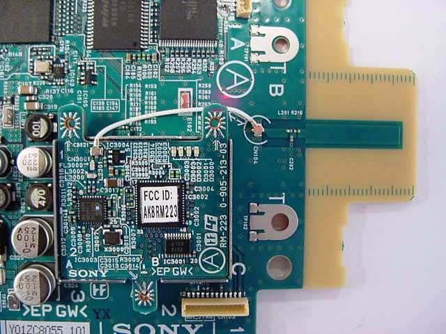
Click to zoom
Application Details
- Equipment Class
- DTS - Digital Transmission System
- Date of Grant
- Feb 21, 2010
- Application Purpose
- Original Equipment
- Date of Application
- Feb 20, 2010
- Equipment Note
- RF Remote Module
- Frequency Range
- 2405.00000000 - 2475.00000000
- Company
- Sony Group Corporation
- Country
- Japan
Documents & Files
Document Text
Text extracted from the exhibit documents filed with the FCC. Open a document above to read the original.
Users Manual
Digital Wireless Receiver F:\Today's works\SONY\9110497\9110497_4177125111_GB\4177125111\4177125111DWRR01DUC\GB01C OV-UC.fm masterpage:Right Operating Instructions Before operating the unit, please read this manual thoroughly and retain it for future reference. DWR-R01D DWR-R01D 4-177-125-11 (1) 4-177-125-11 (1) © 2010 Sony Corporation The supplied CD-ROM includes Operating Instructions for the DWR-R01D Digital Wireless Receiver (English, Japanese, French, German, Italian, and Spanish versions) and the frequency lists (English and Japanese versions) in PDF format. For more details, see “Using the CD-ROMs” on page 10. GB01COV-UC.book Page 1 Wednesday, February 17, 2010 4:50 PM F:\Today's works\SONY\9110497\9110497_4177125111_GB\4177125111\4177125111DWRR01DUC\GB02R EG-UC.fm masterpage:Left DWR-R01D 4-177-125-11 (1) 2 To reduce the risk of fire or electric shock, do not expose this apparatus to rain or moisture. To avoid electrical shock, do not open the cabinet. Refer servicing to qualified personnel only. WARNING THIS APPARATUS MUST BE EARTHED. Important Safety Instructions • Read these instructions. • Keep these instructions. • Heed all warnings. • Follow all instructions. • Do not use this apparatus near water. • Clean only with dry cloth. • Do not block any ventilation openings. Install in accordance with the manufacturer’s instructions. • Do not install near any heat sources such as radiators, heat registers, stoves, or other apparatus (including amplifiers) that produce heat. • Do not defeat the safety purpose of the polarized or grounding-type plug. A polarized plug has two blades with one wider than the other. A grounding-type plug has two blades and a third grounding prong. The wide blade or the third prong are provided for your safety. If the provided plug does not fit into your outlet, consult an electrician for replacement of the obsolete outlet. • Protect the power cord from being walked on or pinched particularly at plugs, convenience receptacles, and the point where they exit from the apparatus. • Only use attachments/accessories specified by the manufacturer. • Use only with the cart, stand, tripod, bracket, or table specified by the manufacturer, or sold with the apparatus. When a cart is used, use caution when moving the cart/apparatus combination to avoid injury from tip-over. • Unplug this apparatus during lightning storms or when unused for long periods of time. • Refer all servicing to qualified service personnel. Servicing is required when the apparatus has been damaged in any way, such as power-supply cord or plug is damaged, liquid has been spilled or objects have fallen into the apparatus, the apparatus has been exposed to rain or moisture, does not operate normally, or has been dropped. CAUTION The apparatus shall not be exposed to dripping or splashing. No objects filled with liquids, such as vases, shall be placed on the apparatus. WARNING Excessive sound pressure from earphones and headphones can cause hearing loss. In order to use this product safely, avoid prolonged listening at excessive sound pressure levels. Suomessa asuville asiakkaille Laite on liitettävä suojamaadoituskoskettimilla varustettuun pistorasiaan For kundene i Norge Apparatet må tilkoples jordet stikkontakt För kunderna i Sverige Apparaten skall anslutas till jordat uttag For the customers in the U.S.A. This equipment has been tested and found to comply with the limits for a Class B digital device, pursuant to Part 15 of the FCC Rules. These limits are designed to provide reasonable protection against harmful interference in a This symbol is intended to alert the user to the presence of uninsulated “dangerous voltage” within the product’s enclosure that may be of sufficient magnitude to constitute a risk of electric shock to persons. This symbol is intended to alert the user to the presence of important operating and maintenance (servicing) instructions in the literature accompanying the appliance. WARNING GB02REG-UC.fm Page 2 Wednesday, February 17, 2010 6:19 PM F:\Today's works\SONY\9110497\9110497_4177125111_GB\4177125111\4177125111DWRR01DUC\GB02R EG-UC.fm masterpage:Right DWR-R01D 4-177-125-11 (1) 3 residential installation. This equipment generates, uses, and can radiate radio frequency energy and, if not installed and used in accordance with the instructions, may cause harmful interference to radio communications. However, there is no guarantee that interference will not occur in a particular installation. If this equipment does cause harmful interference to radio or television reception, which can be determined by turning the equipment off and on, the user is encouraged to try to correct the interference by one or more of the following measures: - Reorient or relocate the receiving antenna. - Increase the separation between the equipment and receiver. - Connect the equipment into an outlet on a circuit different from that to which the receiver is connected. - Consult the dealer or an experienced radio/TV technician for help. You are cautioned that any changes or modifications not expressly approved in this manual could void your authority to operate this equipment. All interface cables used to connect peripherals must be shielded in order to comply with the limits for a digital device pursuant to Subpart B of Part 15 of FCC Rules. If you have any questions about this product, you may call: Sony’s Business Information Center (BIC) at 1-800-686- 7669 or Write to: Sony Customer Information Services Center 6900-29 Daniels Parkway, PMB 330 Fort Myers, Florida 33912 For the customers in Canada Operation is subject to the following two conditions: (1) this device may not cause interference, and (2) this device must accept any interference, including interference that may cause undesired operation of the device. The term “IC:” before the radio certification number only signifies that Industry Canada technical specifications were met. This Class B digital apparatus complies with Canadian ICES-…
Text truncated - open the document above for the full version.
Cover Letter(s)
Applicant/Grantee Sony Corporation FCC ID: AK8RM223 Section 15.212 Modular Transmitters Request for Modular Approval Request for Limited Modular Approval Requirements EUT Conditions Comply (Y/N) Single Modular Approval Requirements 1 The radio elements of the modular transmitter must have their own shielding. The physical crystal and tuning capacitors may be located external to the shielded radio elements. Device is equipped with Metal shielding to cover RF section. However, this module is built in host products equipment (DWR-R01D or RMU-01). And the Metal shield is the part of the host equipment. No 2 The modular transmitter must have buffered modulation/data inputs (if such inputs are provided) to ensure that the module will comply with Part 15 requirements under conditions of excessive data rates or over-modulation. All inputs to the modules are buffered through logic or microprocessor inputs. Yes 3 The modular transmitter must have its own power supply regulation. It does not have own supply regulation. But this module is worked by the regulated power supply from host equipment (DWR-R01D, or RMU-01). No 4 The modular transmitter must comply with the antenna and transmission system requirements of Sections 15.203, 15.204(b) and 15.204(c). The antenna must either be permanently attached or employ a “unique” antenna coupler (at all connections between the module and the antenna, including the cable). The “professional installation” provision of Section 15.203 is not applicable to modules but can apply to limited modular approvals under paragraph (b) of this section. The 1/4λ whip antenna or the 1/4λ monopole antenna are integrated host equipment. The 1/4λwhip antenna is the reverse thread SMA connector. The 1/4λmonopole antenna is into host equipment. Refer to external photos. Yes 5 The modular transmitter must be tested in a stand-alone configuration, i.e., the module must not be inside another device during testing for compliance with Part 15 requirements. Unless the transmitter module will be battery powered, it must comply with the AC line conducted requirements found in Section 15.207. AC or DC power lines and data input/output lines connected to the module must not contain ferrites, unless they will be marketed with the module (see Section 15.27(a)). The length of these lines shall be the length typical of actual use or, if that length is Device was tested inside the hosts of DWR-R01D and RMU-01. Refer to setup photos. No unknown, at least 10 centimeters to insure that there is no coupling between the case of the module and supporting equipment. Any accessories, peripherals, or support equipment connected to the module during testing shall be unmodified and commercially available (see Section 15.31(i)). 6 The modular transmitter must be equipped with either a permanently affixed label or must be capable of electronically displaying its FCC identification number. (A) If using a permanently affixed label, the modular transmitter must be labeled with its own FCC identification number, and, if the FCC identification number is not visible when the module is installed inside another device, then the outside of the device into which the module is installed must also display a label referring to the enclosed module. This exterior label can use wording such as the following: “Contains Transmitter Module FCC ID: XYZMODEL1” or “Contains FCC ID: XYZMODEL1.” Any similar wording that expresses the same meaning may be used. The Grantee may either provide such a label, an example of which must be included in the application for equipment authorization, or, must provide adequate instructions along with the module which explain this requirement. In the latter case, a copy of these instructions must be included in the application for equipment authorization. (B) If the modular transmitter uses an electronic display of the FCC identification number, the information must be readily accessible and visible on the modular transmitter or on the device in which it is installed. If the module is installed inside another device, then the outside of the device into which the module is installed must display a label referring to the enclosed module. This exterior label can use wording such as the following: “Contains FCC certified transmitter module(s).” Any similar wording that expresses the same meaning may be used. The user manual must include instructions on how to access the electronic display. A copy of these instructions must be included in the application for equipment authorization. The module is labeled with its own FCC ID. And FCC ID is displayed on the spec label of host equipment. Yes 7 The modular transmitter must comply with any specific rules or operating requirements that ordinarily apply to a complete transmitter and the manufacturer must provide adequate instructions along with the module to explain any such This module is built in type. Then user can not operation with outside the scope of the regulation. Yes requirements. A copy of these instructions must be included in the application for equipment authorization. 8 The modular transmitter must comply with any applicable RF exposure requirements in its final configuration. Meet RF exposure compliance requirement. Yes A limited modular approval may be granted for single or split modular transmitters that do not comply with all of the above requirements, e.g., shielding, minimum signaling amplitude, buffered modulation/data inputs, or power supply regulation, if the manufacturer can demonstrate by alternative means in the application for equipment authorization that the modular transmitter meets all the applicable Part 15 requirements under the operating conditions in which the transmitter will be used. Limited modular approval also may be granted in those instances where compliance with RF exposure rules is demonstrated only for particular product configurations. The applicant for certification must state how control of the end product int…
Text truncated - open the document above for the full version.
External Photos
Photo Document Model RM-223 <1/3> Fig.1 RM-223(A) Fig.2 RM-223(B) Photo Document Model RM-2 23 (For DWR-R01D) <2/3> Fig.3 RM-223 (with DWR-R01D’s Antenna) Fig.4 CN-3264(A) Fig.5 CN-3264(B) Fig.6 DWR-R01D’s Antenna Photo Document Model RM-223 (For RMU-01) <3/3> Fig.7 RM-223 (with RMU-01’s Antenna) Fig.8 NET-10(A) Antenna Fig.9 NET-10(B) Fig.8 RM-223(Detach NET-10)
External Photos
External Photograph of the Host Equipment ・ Host Model : DWR-R01D - Front View - - Rear View - External Photograph of the Host Equipment ・ Host Model : RMU-01 - X axis - - Y axis - - Z axis -
ID Label/Location Info
1/2 Label Information of the Host Equipment Receiver (Model No. : DWR-R01D) 2/2 Remote Control Unit (Model No. : RMU-01)
ID Label/Location Info
Marking position for FCC ID
Internal Photos
Photo Document Model RM-223 <1/3> Fig.1 RM-223(A) Fig.2 RM-223(B) Photo Document Model RM-2 23 (For DWR-R01D) <2/3> Fig.3 RM-223 (with DWR-R01D’s Antenna) Fig.4 CN-3264(A) Fig.5 CN-3264(B) Fig.6 DWR-R01D’s Antenna Photo Document Model RM-223 (For RMU-01) <3/3> Fig.7 RM-223 (with RMU-01’s Antenna) Fig.8 NET-10(A) Antenna Fig.9 NET-10(B) Fig.8 RM-223(Detach NET-10)
Test Report
Page 1 of 69 Technical document No. 23160-0701 JQA File No. : 400-090301 Issue Date : December 22, 2009 TEST REPORT APPLICANT : Sony Corporation ADDRESS : 1-7-1 Konan, Minato-ku, Tokyo, 108-0075, Japan PRODUCTS : RF Remote Module MODEL No. : RM-223 SERIAL No. : None FCC ID : AK8RM223 IC : 409B-RM223 TEST STANDARD : CFR 47 FCC Rules and Regulations Part 15 Subpart A, B and C : Industry Canada RSS-210(Issue 7) and RSS-Gen(Issue 2) TESTING LOCATION : Japan Quality Assurance Organization SAFETY & EMC CENTER EMC Engineering Department Testing Division 1-21-25, Kinuta, Setagaya-ku, Tokyo 157-8573, Japan TEST RESULTS : Passed DATE OF TEST : November 13, 2009 - November 26, 2009 This report must not used by the client to claim product endorsement by NVLAP or NIST or any agency of the U.S. Government. Eiichi Saegusa Manager Japan Quality Assurance Organization SAFETY & EMC CENTER EMC Engineering Dept. Testing Division NVLAP LAB CODE 200189 -0 1-21-25, Kinuta, Setagaya-ku, Tokyo 157-8573, Japan ● The measurement values stated in Test Report was made with traceable to National Institute of Advanced Industrial Science and Technology (AIST) of Japan and National Institute of Information and Communications Technology (NICT) of Japan. ● The applicable standard, testing condition and testing method which were used for the tests are based on the request of the applicant. ● The test results presented in this report relate only to the offered test sample. ● The contents of this test report cannot be used for the purposes, such as advertisement for consumers. ● This test report shall not be reproduced except in full without the written approval of JQA. JQA File No. : 400-090301 Issue Date : December 22, 2009 Model No. : RM-223 FCC ID : AK8RM223 IC : 409B-RM223 Standard : FCC Part 15 / RSS-210(Issue 7) and RSS-Gen(Issue 2) Page 2 of 69 Technical document No. 23160-0701 Table of Contents Documentation Page 1 Test Regulation 3 2 Test Location 3 3 Recognition of Test Laboratory 3 4 Description of the Equipment Under Test 4 5 Test Condition 5-12 6 Preliminary Test and Test Setup 13-21 7 Equipment Under Test Modification 22 8 Responsible Party 22 9 Deviation from Standard 22 10 Test Results 23-29 11 Summary 30 12 Operating Condition 31 13 Test Configuration 32 14 Equipment Under Test Arrangement (Drawings) 33 Appendix A : Test Data 34-60 A.1 Channel Separation A.2 Minimum Hopping Channel A.3 Occupied Bandwidth A.4 Dwell Time A.5 Peak Output Power (Conduction) A.6 Peak Output Power (Radiation) A.7 Peak Power Density (Conduction) A.8 Peak Power Density (Radiation) A.9 Spurious Emissions (Conduction) A.10 Spurious Emissions for Transmitter (Radiation) A.11 AC Power Line Conducted Emissions for Transmitter A.12 RF Exposure Compliance A.13 Spurious Emissions for Receiver (Radiation) A.14 AC Power Line Conducted Emissions for Receiver Appendix B : Test Arrangement (Photographs) 61-66 Appendix C : Test Instruments 67-69 Definitions for Abbreviation and Symbols Used In This Test Report “EUT” means Equipment Under the Test. “AE” means Associated Equipment. “N/A” means that Not Applicable. “N/T” means that Not Tested. -indicates that the listed condition, standard or equipment is applicable for this report. -indicates that the listed condition, standard or equipment is not applicable for this report. JQA File No. : 400-090301 Issue Date : December 22, 2009 Model No. : RM-223 FCC ID : AK8RM223 IC : 409B-RM223 Standard : FCC Part 15 / RSS-210(Issue 7) and RSS-Gen(Issue 2) Page 3 of 69 Technical document No. 23160-0701 Documentation 1 Test Regulation Applied Standard : CFR 47 FCC Rules and Regulations Part 15 Subpart A, B and C Industry Canada RSS-210(Issue 7) and RSS-Gen(Issue 2) Test Procedure : The tests were performed with reference to the FCC Public Notice DA 00-705, released March 30, 2000. The test set-up was made in accordance to the general provisions of ANSI C63.4-2003. 2 Test Location Japan Quality Assurance Organization SAFETY & EMC CENTER EMC Engineering Department Testing Division 1-21-25, Kinuta, Setagaya-ku, Tokyo 157-8573, Japan 3 Recognition of Test Laboratory Japan Quality Assurance Organization SAFETY & EMC CENTER EMC Engineering Department Testing Division is accredited under ISO/IEC 17025 by following accreditation bodies and the test facility of Testing Division is registered by the following bodies . VLAC Code : VLAC-001-1 (Effective through : April 3, 2010) NVLAP Lab Code : 200189-0 (Effective through : June 30, 2010) VCCI Registration Number : R-002, R-003, C-002, C-966 (Effective through : April 3, 2010) FCC Registration Number : 349652 (Date of Listing : April 1, 2010) IC Registration Number : 2079-7, 2079-8 (Effective through : August 29, 2011) Accredited as conformity assessment body for Japan electrical appliances and material law by METI. (Effective through : February 22, 2010) JQA File No. : 400-090301 Issue Date : December 22, 2009 Model No. : RM-223 FCC ID : AK8RM223 IC : 409B-RM223 Standard : FCC Part 15 / RSS-210(Issue 7) and RSS-Gen(Issue 2) Page 4 of 69 Technical document No. 23160-0701 4 Description of the Equipment Under Test 1 Manufacturer : Sony EMCS Corporation Kosai Tec. 554 Sakaijuku Kosai-shi, Shizuoka-ken, 431-0496, Japan 2 Products : RF Remote Module 3 Trade Name : SONY 4 Model No. : RM-223 5 Serial No. : None 6 FCC ID : AK8RM223 7 IC : 409B-RM223 8 Product Type : Prototype 9 Date of Manufacture : None 10 Power Rating : 3.3 VDC to 5.0VDC (from the Host Equipment) 11 EUT Grounding : None 12 Category : Transceiver(DSSS type) 13 Received Date of EUT : November 13, 2009 14 EUT Authorization : Certification 15 Fundamental Frequency Generated/used in the EUT : 16 MHz 16 Operating Frequency Range : 2405 MHz - 2475 MHz 17 EUT Highest Frequency Used/Generated : 2475 MHz 18 RF Output Power : 0.36 dBm(measured value) 19 Antenna Type : λ/4 Whip Antenna (The reverse thread SMA connector) or λ/4 Monopole Antenna (Integral Internal antenna : not accessible to the user) 20 Antenna Gain : 0.3 d…
Text truncated - open the document above for the full version.
Test Report
JQA File No. : 400-090301-Add Issue Date : February 12, 2010 Model No. : RM-223 FCC ID : AK8RM223 IC : 409B-RM223 Standard : FCC Part 15 / RSS-210(Issue 7) and RSS-Gen(Issue 2) Page 1 of 26 Technical document No. 23160-0701 The result of having tested by including the EUT in the host equipments is shown after the following page. The host equipments are the Digital Wireless Receiver(Model No. : DWR-R01D) and the Remote Control Unit(Model No. : RMU-01). COPY JQA File No. : 400-090301-Add Issue Date : February 12, 2010 Model No. : RM-223 FCC ID : AK8RM223 IC : 409B-RM223 Standard : FCC Part 15 / RSS-210(Issue 7) and RSS-Gen(Issue 2) Page 2 of 26 Technical document No. 23160-0701 Appendix X : Additional Test Data X.1 Spurious Emissions for Transmitter (Radiation) X.1.1 Band Edge Compliance X.1.1.1 Host Model : DWR-R01D Date : February 12, 2010 Temp. : 19 ºC Humi. : 43 % Mode of EUT : TX Mode (11ch : 2405 MHz, 25ch : 2475 MHz) Test Port : Enclosure Antenna Polarization : Horizontal Note : The trace 1 is Peak detection. The Trace 2 is Average detection. Trace 1 Trace 2 Trace 1 Trace 2 COPY JQA File No. : 400-090301-Add Issue Date : February 12, 2010 Model No. : RM-223 FCC ID : AK8RM223 IC : 409B-RM223 Standard : FCC Part 15 / RSS-210(Issue 7) and RSS-Gen(Issue 2) Page 3 of 26 Technical document No. 23160-0701 Mode of EUT : TX Mode (11ch : 2405 MHz, 25ch : 2475 MHz) Test Port : Enclosure Antenna Polarization : Vertical Note : The trace 1 is Peak detection. The Trace 2 is Average detection. Trace 1 Trace 2 Trace 1 Trace 2 COPY JQA File No. : 400-090301-Add Issue Date : February 12, 2010 Model No. : RM-223 FCC ID : AK8RM223 IC : 409B-RM223 Standard : FCC Part 15 / RSS-210(Issue 7) and RSS-Gen(Issue 2) Page 4 of 26 Technical document No. 23160-0701 X.1.1.2 Host Model : RMU-01 Date : February 12, 2010 Temp. : 19 ºC Humi. : 43 % Mode of EUT : TX Mode (11ch : 2405 MHz, 25ch : 2475 MHz) Test Port : Enclosure Antenna Polarization : Horizontal Note : The trace 1 is Peak detection. The Trace 2 is Average detection. Trace 1 Trace 2 Trace 1 Trace 2 COPY JQA File No. : 400-090301-Add Issue Date : February 12, 2010 Model No. : RM-223 FCC ID : AK8RM223 IC : 409B-RM223 Standard : FCC Part 15 / RSS-210(Issue 7) and RSS-Gen(Issue 2) Page 5 of 26 Technical document No. 23160-0701 Mode of EUT : TX Mode (11ch : 2405 MHz, 25ch : 2475 MHz) Test Port : Enclosure Antenna Polarization : Vertical Note : The trace 1 is Peak detection. The Trace 2 is Average detection. Trace 1 Trace 2 Trace 1 Trace 2 COPY JQA File No. : 400-090301-Add Issue Date : February 12, 2010 Model No. : RM-223 FCC ID : AK8RM223 IC : 409B-RM223 Standard : FCC Part 15 / RSS-210(Issue 7) and RSS-Gen(Issue 2) Page 6 of 26 Technical document No. 23160-0701 X.1.2 Other Spurious Emissions X.1.2.1 Spurious Emissions in the frequency range from 9 kHz to 30 MHz X.1.2.1.1 Host Model : DWR-R01D Date : February 12, 2010 Temp. : 19 ºC Humi. : 43 % Mode of EUT : All modes have been investigated and worst case mode for Channel (25ch : 2475 MHz) has been listed. Test Port : Enclosure No spurious emissions of the EUT in the range 20 dB below the limit. X.1.2.1.2 Host Model : RMU-01 Date : February 12, 2010 Temp. : 19 ºC Humi. : 43 % Mode of EUT : All modes have been investigated and worst case mode for Channel (25ch : 2475 MHz) has been listed. Test Port : Enclosure No spurious emissions of the EUT in the range 20 dB below the limit. COPY JQA File No. : 400-090301-Add Issue Date : February 12, 2010 Model No. : RM-223 FCC ID : AK8RM223 IC : 409B-RM223 Standard : FCC Part 15 / RSS-210(Issue 7) and RSS-Gen(Issue 2) Page 7 of 26 Technical document No. 23160-0701 X.1.2.2 Spurious Emissions in the frequency range from 30 MHz to 1000 MHz X.1.2.2.1 Host Model : DWR-R01D Date : February 12, 2010 Temp. : 19 ºC Humi. : 43 % Mode of EUT : All modes have been investigated and worst case mode for Channel (25ch : 2475 MHz) has been listed. Test Port : Enclosure Frequ-P-ACorrectionPolari-Meter Reading LimitsEmission LevelsMargins encyFactorFactorz ation (dBuV) (dBuV/m)(dBuV/m)(dB) (MHz)(dB)(dB)QPAVPeakQP/AVPeakQP/AVPeakQP/AVPeak 49.170.015.2V8.4- - 40.0- 23.6- 16.4- 67.210.010.7H22.3- - 40.0- 33.0- 7.0- 172.800.020.3H5.2- - 43.5- 25.5- 18.0- 228.450.021.7V2.6- - 46.0- 24.3- 21.7- 266.550.022.7V2.5- - 46.0- 25.2- 20.8- 320.000.019.0V4.3- - 46.0- 23.3- 22.7- 466.960.022.7V1.7- - 46.0- 24.4- 21.6- 932.620.029.2V1.7- - 46.0- 30.9- 15.1- X.1.2.2.2 Host Model : RMU-01 Date : February 12, 2010 Temp. : 19 ºC Humi. : 43 % Mode of EUT : All modes have been investigated and worst case mode for Channel (25ch : 2475 MHz) has been listed. Test Port : Enclosure Frequ-P-ACorrectionPolari-Meter Reading LimitsEmission LevelsMargins encyFactorFactorz ation (dBuV) (dBuV/m)(dBuV/m)(dB) (MHz)(dB)(dB)QPAVPeakQP/AVPeakQP/AVPeakQP/AVPeak 30.600.021.8V13.9- - 40.0- 35.7- 4.3- 43.760.017.1V12.6- - 40.0- 29.7- 10.3- 63.000.011.4V18.8- - 40.0- 30.2- 9.9- 108.360.015.7V6.1- - 43.5- 21.8- 21.7- 125.000.017.7H5.3- - 43.5- 23.0- 20.5- 474.960.022.8V10.1- - 46.0- 32.9- 13.1- 550.000.024.2H9.7- - 46.0- 33.9- 12.1- 574.960.024.7H13.1- - 46.0- 37.8- 8.2- 625.000.025.4H11.9- - 46.0- 37.3- 8.8- COPY JQA File No. : 400-090301-Add Issue Date : February 12, 2010 Model No. : RM-223 FCC ID : AK8RM223 IC : 409B-RM223 Standard : FCC Part 15 / RSS-210(Issue 7) and RSS-Gen(Issue 2) Page 8 of 26 Technical document No. 23160-0701 Note : 1) The spectrum was checked from 30 MHz to 1000 MHz. 2) The cable loss, amp. gain and antenna factor are included in the correction factor. 3) The symbol of “<” means “or less”. 4) The symbol of “>” means “or greater”. 5) A sample calculation(QP/AV) was made at 49.17 MHz of Host Model : DWR-R01D. PA + CF + MR = 0 + 15.2 + 8.4 = 23.6 (dBuV/m) PA : Peak to Average Factor (P-A Factor) CF : Correction Factor MR : Meter Reading 6) Measuring Instruments Setting : Detector Function Resolution Bandwidth Video Bandwidth Quasi-peak (QP) 120 kHz -- COPY JQA File No. : 400-090301-Add Issue Date : February 12, 2…
Text truncated - open the document above for the full version.
Test Setup Photos
JQA File No. : 400-090301 Issue Date : December 22, 2009 Model No. : RM-223 FCC ID : AK8RM223 IC : 409B-RM223 Standard : FCC Part 15 / RSS-210(Issue 7) and RSS-Gen(Issue 2) Page 61 of 69 Technical document No. 23160-0701 Appendix B : Test Arrangement (Photographs) B.1.1 External EUT λ/4 Whip Antenna λ/4 Monopole Antenna Controller COPY JQA File No. : 400-090301 Issue Date : December 22, 2009 Model No. : RM-223 FCC ID : AK8RM223 IC : 409B-RM223 Standard : FCC Part 15 / RSS-210(Issue 7) and RSS-Gen(Issue 2) Page 62 of 69 Technical document No. 23160-0701 B.1.3 Radiated Emissions B.1.3.1 Used Antenna : λ/4 Whip Antenna - X-axis - - Y-axis - Photograph present configuration with maximum emission COPY JQA File No. : 400-090301 Issue Date : December 22, 2009 Model No. : RM-223 FCC ID : AK8RM223 IC : 409B-RM223 Standard : FCC Part 15 / RSS-210(Issue 7) and RSS-Gen(Issue 2) Page 63 of 69 Technical document No. 23160-0701 - Z-axis - Photograph present configuration with maximum emission COPY JQA File No. : 400-090301 Issue Date : December 22, 2009 Model No. : RM-223 FCC ID : AK8RM223 IC : 409B-RM223 Standard : FCC Part 15 / RSS-210(Issue 7) and RSS-Gen(Issue 2) Page 64 of 69 Technical document No. 23160-0701 B.1.3.1 Used Antenna : λ/4 Monopole Antenna - X-axis - - Y-axis - Photograph present configuration with maximum emission COPY JQA File No. : 400-090301 Issue Date : December 22, 2009 Model No. : RM-223 FCC ID : AK8RM223 IC : 409B-RM223 Standard : FCC Part 15 / RSS-210(Issue 7) and RSS-Gen(Issue 2) Page 65 of 69 Technical document No. 23160-0701 - Z-axis - Photograph present configuration with maximum emission COPY
Test Setup Photos
JQA File No. : 400-090301-Add Issue Date : February 12, 2010 Model No. : RM-223 FCC ID : AK8RM223 IC : 409B-RM223 Standard : FCC Part 15 / RSS-210(Issue 7) and RSS-Gen(Issue 2) Page 21 of 26 Technical document No. 23160-0701 Appendix Y : Test Arrangement (Photographs) Y.1 External Y.1.1 Host Model : DWR-R01D Y.1.2 Host Model : RMU-01 COPY JQA File No. : 400-090301-Add Issue Date : February 12, 2010 Model No. : RM-223 FCC ID : AK8RM223 IC : 409B-RM223 Standard : FCC Part 15 / RSS-210(Issue 7) and RSS-Gen(Issue 2) Page 22 of 26 Technical document No. 23160-0701 Y.2 Radiated Emissions Y.2.1 Host Model : DWR-R01D - Front View - - Rear View - Photograph present configuration with maximum emission COPY JQA File No. : 400-090301-Add Issue Date : February 12, 2010 Model No. : RM-223 FCC ID : AK8RM223 IC : 409B-RM223 Standard : FCC Part 15 / RSS-210(Issue 7) and RSS-Gen(Issue 2) Page 23 of 26 Technical document No. 23160-0701 Y.2.2 Host Model : RMU-01 - X axis - - Y axis - Photograph present configuration with maximum emission COPY JQA File No. : 400-090301-Add Issue Date : February 12, 2010 Model No. : RM-223 FCC ID : AK8RM223 IC : 409B-RM223 Standard : FCC Part 15 / RSS-210(Issue 7) and RSS-Gen(Issue 2) Page 24 of 26 Technical document No. 23160-0701 - Z axis - Photograph present configuration with maximum emission COPY JQA File No. : 400-090301-Add Issue Date : February 12, 2010 Model No. : RM-223 FCC ID : AK8RM223 IC : 409B-RM223 Standard : FCC Part 15 / RSS-210(Issue 7) and RSS-Gen(Issue 2) Page 25 of 26 Technical document No. 23160-0701 B.3 AC Power Line Conducted Emissions Y.3.1 Host Model : DWR-R01D - Front View - - Side View - Photograph present configuration with maximum emission COPY JQA File No. : 400-090301-Add Issue Date : February 12, 2010 Model No. : RM-223 FCC ID : AK8RM223 IC : 409B-RM223 Standard : FCC Part 15 / RSS-210(Issue 7) and RSS-Gen(Issue 2) Page 26 of 26 Technical document No. 23160-0701 Y.3.2 Host Model : RMU-01 - Front View - - Side View - Photograph present configuration with maximum emission COPY
Contact Information
Applicant
Kazuyuki Hori(Chief EMC/RF Compliance Specialist)
Test Firm
Japan Qlty. Assur. Org. Kitakansai Testing CenterHiroyuki Nakamura
Technical Specifications
| # | Rule Parts | Frequency Range | Power Output |
|---|---|---|---|
| 1 | 15C | 2.40 GHz - 2.48 GHz | 1.00 mW |
Other Applications from Sony Group Corporation
AK8WW81782
Aug 21, 2026Radio Equipment
Equipment Class
DSS - Part 15 Spread Spectrum TransmitterAK8CFIZCP2
Aug 03, 2026Wireless Controller
Equipment Class
DSS - Part 15 Spread Spectrum TransmitterAK8OEV321MUH
Apr 14, 2026LCD Monitor
Equipment Class
JAD - Part 15 Class A Digital DeviceAK8OEV431MUH
Apr 14, 2026LCD Monitor
Equipment Class
JAD - Part 15 Class A Digital DeviceAK8OEV271MUH
Apr 14, 2026LCD Monitor
Equipment Class
JAD - Part 15 Class A Digital Device