AK8RMTP100Low Power Communication Device Transmitter
Sony Group Corporation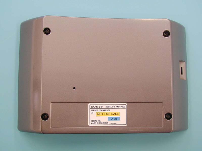
Click to zoom
Application Details
- Equipment Class
- DXX - Part 15 Low Power Communication Device Transmitter
- Date of Grant
- Mar 18, 2004
- Application Purpose
- Original Equipment
- Date of Application
- Mar 18, 2004
- Equipment Note
- Low Power Communication Device Transmitter
- Frequency Range
- 916.50000000 - 916.50000000
- Company
- Sony Group Corporation
- Country
- Japan
Documents & Files
Document Text
Text extracted from the exhibit documents filed with the FCC. Open a document above to read the original.
Users Manual
4-253-728-11(1) Custom Integrated AV System 2004 Sony Corporation CAV-M1000ES Installation Manual Owner’s Record The model and serial numbers are located on the rear panel. Record the model and serial numbers in the spaces provided below. Refer to them whenever you call upon your Sony dealer regarding this product. Model No.Serial No. 2 WARNING To prevent fire or shock hazard, do not expose the unit to rain or moisture. To avoid electrical shock, do not open the cabinet. Refer servicing to qualified personnel only. This symbol is intended to alert the user to the presence of uninsulated “dangerous voltage” within the product’s enclosure that may be of sufficient magnitude to constitute a risk of electric shock to persons. This symbol is intended to alert the user to the presence of important operating and maintenance (servicing) instructions in the literature accompanying the appliance. WARNING This equipment has been tested and found to comply with the limits for a Class B digital device, pursuant to Part 15 of the FCC Rules. These limits are designed to provide reasonable protection against harmful interference in a residential installation. This equipment generates, uses, and can radiate radio frequency energy and, if not installed and used in accordance with the instructions, may cause harmful interference to radio communications. However, there is no guarantee that interference will not occur in a particular installation. If this equipment does cause harmful interference to radio or television reception, which can be determined by turning the equipment off and on, the user is encouraged to try to correct the interference by one or more of the following measures: – Reorient or relocate the receiving antenna. – Increase the separation between the equipment and receiver. – Connect the equipment to an outlet on a circuit different from that to which the receiver is connected. – Consult the dealer or an experienced radio/TV technician for help. CAUTION You are cautioned that any changes or modification not expressly approved in this manual could void your authority to operate this equipment. If you have any questions about this product, you may call; Sony Customer Information Services Center 1-800-222-7669 or http://www.sony.com Declaration of Conformity Trade name: SONY Model No.: CAV-M1000ES Responsible Party: Sony Electronics Inc. Address: 680 Kinderkamack Road, Oradell, NJ 07649 USA Telephone No.: 201-930-6972 This device complies with Part 15 of the FCC Rules. Operation is subject to the following two conditions: (1) This device may not cause harmful interference, and (2) this device must accept any interference received, including interference that may cause undesired operation. Declaration of Conformity Trade name: SONY Model No.: RM-TP100 Responsible Party: Sony Electronics Inc. Address: 680 Kinderkamack Road, Oradell, NJ 07649 USA Telephone No.: 201-930-6972 This device complies with Part 15 of the FCC Rules. Operation is subject to the following two conditions: (1) This device may not cause harmful interference, and (2) this device must accept any interference received, including interference that may cause undesired operation. Important Safety Instruction 1 Read these instructions. 2 Keep these instructions. 3 Heed all warnings. 4 Follow all instructions. 5 Do not use this apparatus near water. 6 Clean only with dry cloth. 7 Do not block any ventilation openings. Install in accordance with the manufacturer’s instrucitons. 8 Do not install near any heat sources such as radiators, heat registers, stoves, or other apparatus (including amplifiers) that produce heat. 9 Do not defeat the safety purpose of the polarized or grounding-type plug. A polarized plug has two blades with one wider than the other. A grounding type plug has two blades and a third grounding prong. The wide blade or the third prong are provided for your safety. If the provided plug does not fit into your outlet, consult an electrician for replacement of the obsolete outlet. 10Protect the power cord from being walked on or pinched particularly at plugs, convenience receptacles, and the point where they exit from the apparatus. 11Only use attachments/accessories specified by the manufacturer. 12 Use only with the cart, stand, tripod, bracket, or table specified by the manufacturer, or sold with the apparatus. When a cart is used, use caution when moving the cart/apparatus combination to avoid injury from tip-over. 13Unplug this apparatus during lightning storms or when unused for long periods of time. 14Refer all servicing to qualified service personnel. Servicing is required when the apparatus has been damaged in any way, such as power-supply cord or plug is damaged, liquid has been spilled or objects have fallen into the apparatus, the apparatus has been exposed to rain or moisture, does not operate normally, or has been dropped. Welcome! Thank you for purchasing the Sony Custom Integrated AV System. Before operating the unit, please read this manual thoroughly and retain it for future reference. 3 TABLE OF CONTENTS Chapter 1 Getting Started Features4 Unpacking 6 Parts and Controls7 Before Customizing the System 14 Chapter 2 Setting up the Main Unit Installing the Main Unit 15 Hooking up the Main Unit 16 Selecting the Source and the Volume Level of the Main Unit18 Setting up the Remote Code and the Baud Rate – SETUP mode19 Learning the Remote Code for a Connected Component – LEARN Mode20 Testing Learned Remote Code – CHECK Mode 22 Customizing the Main Unit – INSTALLATION Mode22 Chapter 3 Setting up the Keypad Installing the Keypad 25 Hooking up in Each Zone 27 Customizing the Keypad 28 Testing the Components 29 Chapter 4 Other Information Precautions30 Troubleshooting 31 Error Messages 32 Specifications 33 Chapter 5 Appendix LEARN Mode Code List 34 Index37 Using the RF Remote Control 39 Using the Keypad 40 Using the IR Remote Control for the Keypad 41 4 Chapter 1 Getting Started This chapter provides you with …
Text truncated - open the document above for the full version.
External Photos
External Photo (Remote Commander) FCC ID: AK8MTP100 Sony EMCS Corporation front Bottom
Internal Photos
Internal Photo (Remote Commander) FCC ID: AK8MTP100 Sony EMCS Corporation front without cover 1 front with cover 2 Internal Photo (Remote Commander) FCC ID: AK8MTP100 Sony EMCS Corporation RF Module (Front) RF Module (Back) Internal Photo (Remote Commander) FCC ID: AK8MTP100 Sony EMCS Corporation RF Module (Enlargement 1) RF Module (Enlargement 2)
Test Report
FCC ID : AK8RMTP100 Test report No. : 24FE0244-YK-2 Page : 2 of 21 Issued date : February 25, 2004 UL Apex Co., Ltd. YAMAKITA EMC LAB. 907 Kawanishi, Yamakita-machi, Ashigarakami-gun, Kanagawa-ken, 258-0124 JAPAN Telephone: +81 465 77 1011 Facsimile: +81 465 77 2112 MF060b(23.04.02) Table of Contents Page 1 GENERAL INFORMATION 3 1.1 Tested Methodology 3 1.2 Test Facility 3 2 PRODUCT DESCRIPTION 4 3 SYSTEM TEST CONFIGURATION 5 3.1 Justification 5 3.2.Configuration of Tested System 5 4 MEASUREMENT UNCERTAINTY 6 5 SUMMARY OF TESTS 7 5.1 §15.207 Conducted Emissions 7 5.2 §15.249 (a) & (d) Field Strength (Radiated Emissions) 8 5.3 26dB Bandwidth 8 Contents of Appendixes 9 APPENDIX 1: Photographs of test setup 10 APPENDIX 2: Test Data 13 APPENDIX 3: Test instruments 21 FCC ID : AK8RMTP100 Test report No. : 24FE0244-YK-2 Page : 3 of 21 Issued date : February 25, 2004 UL Apex Co., Ltd. YAMAKITA EMC LAB. 907 Kawanishi, Yamakita-machi, Ashigarakami-gun, Kanagawa-ken, 258-0124 JAPAN Telephone: +81 465 77 1011 Facsimile: +81 465 77 2112 MF060b(23.04.02) 1 GENERAL INFORMATION Applicant Company Name : Sony EMCS Corporation Kisarazu TEC Brand Name : SONY Address : 8-4 Shiomi, Kisarazu-shi, Chiba-ken, 292-0834 Japan Telephone Number : +81 438 37 3982 Facsimile Number : +81 438 37 4069 Contact Person : Shunichi Yamamoto ([email protected]) Type of Equipment : Remote Commander Model No. : RM-TP100 Serial No. : A25 Rating : DC 3.3V Receipt Date of Sample : January 23, 2004 Condition of EUT : Production prototype Regulation(s) : FCC Part15 Subpart C, Section 15.249 Test Site : UL Apex No.2 Open Test Site 1.1 Tested Methodology The measurements were performed according to the procedures in ANSI C63.4 (2001). 1.2 Test Facility This site has been fully described in a report submitted to FCC office, and accepted on December 8, 2000 (Registration No.: 99354). NVLAP Lab. code : 200441-0 FCC ID : AK8RMTP100 Test report No. : 24FE0244-YK-2 Page : 4 of 21 Issued date : February 25, 2004 UL Apex Co., Ltd. YAMAKITA EMC LAB. 907 Kawanishi, Yamakita-machi, Ashigarakami-gun, Kanagawa-ken, 258-0124 JAPAN Telephone: +81 465 77 1011 Facsimile: +81 465 77 2112 MF060b(23.04.02) 2 PRODUCT DESCRIPTION Model: RM-TP100 (referred to as the EUT in this report) is a Remote Commander. The clock frequency used in EUT : 20MHz Frequency characteristics : 916.5MHz Number of channels : Single Modulation : OOK (On-Off Keyed) Antenna type : Loop Antenna Gain : 2.0dBi Operating Voltage : DC 3.3V Operating temperature : 0 - 40 deg. C. *FCC Part15.31 (e) The remote commander provides RF module with stable power supply (DC3.3V), and the power is not changed when voltage of the remote commander is varied. Therefore, the Remote Commander complies power supply regulation. *FCC Part15.203 The remote commander and its antenna comply with this requirement since this antenna is soldered in RF module directly and it cannot be dismounted by end users. FCC ID : AK8RMTP100 Test report No. : 24FE0244-YK-2 Page : 5 of 21 Issued date : February 25, 2004 UL Apex Co., Ltd. YAMAKITA EMC LAB. 907 Kawanishi, Yamakita-machi, Ashigarakami-gun, Kanagawa-ken, 258-0124 JAPAN Telephone: +81 465 77 1011 Facsimile: +81 465 77 2112 MF060b(23.04.02) 3 SYSTEM TEST CONFIGURATION 3.1 Justification The system was configured in typical fashion (as a customer would normally use it) for testing. Test mode: Transmitting mode * Charging operation 3.2 Configuration of Tested System Front View Top View Description of EUT and support equipment No. Item Model number Serial number Manufacture FCC ID Remarks A Remote Commander RM-TP100 A25 SONY AK8RMTP100 EUT B Remote Commander Base Unit RMB-TP100 B16 SONY - - List of cables used No. Name Length (m) Shield Backshell material 1 AC Power Cable 1.8 Unshielded Polyvinyl chloride * RS232C port is used only when dealers check operation or customize the equipment. A: EUT B AC120V/ 60Hz : Ferrite core B A: EUT 1 1 FCC ID : AK8RMTP100 Test report No. : 24FE0244-YK-2 Page : 6 of 21 Issued date : February 25, 2004 UL Apex Co., Ltd. YAMAKITA EMC LAB. 907 Kawanishi, Yamakita-machi, Ashigarakami-gun, Kanagawa-ken, 258-0124 JAPAN Telephone: +81 465 77 1011 Facsimile: +81 465 77 2112 MF060b(23.04.02) 4 MEASUREMENT UNCERTAINTY Conducted emission test The measurement uncertainty (with a 95% confidence level) for this test was ±1.3dB. The data listed in this test report has enough margin, more than site margin. Radiated emission test The measurement uncertainty (with 95% confidence level) for this test using Biconical antenna is ±4.8dB. The measurement uncertainty (with 95% confidence level) for this test using Logperiodic antenna is ±5.2dB. The measurement uncertainty (with 95% confidence level) for this test using Horn antenna is ±6.6dB. The result is within Yamakita EMC lab’s uncertainty. FCC ID : AK8RMTP100 Test report No. : 24FE0244-YK-2 Page : 7 of 21 Issued date : February 25, 2004 UL Apex Co., Ltd. YAMAKITA EMC LAB. 907 Kawanishi, Yamakita-machi, Ashigarakami-gun, Kanagawa-ken, 258-0124 JAPAN Telephone: +81 465 77 1011 Facsimile: +81 465 77 2112 MF060b(23.04.02) 5 SUMMARY OF TESTS 5.1 §15.207 Conducted Emissions Test Procedure EUT was placed on a platform of nominal size, 1m by 1.8m, raised 80cm above the conducting ground plane. The rear of tabletop was located 40cm to the vertical conducting plane. The rear of EUT, including peripheral was aligned and flushed with rear of tabletop. All other surfaces of tabletop were at least 80cm from any other grounded conducting surface. EUT was located 80cm from LISN, and excess AC cable was bundled in center. It was folded back and forth forming a bundle 30cm to 40cm long. Each EUT current-carrying power lead, except the ground (safety) lead, was individually connected through a LISN to the input power source. The AC Mains Terminal Continuous disturbance Voltage has been measured with the EUT on a shielded room. The EUT was connected to a Line Impedance Stabilization Network (LISN). An overview sweep w…
Text truncated - open the document above for the full version.
Test Setup Photos
FCC ID : AK8RMTP100 Test report No. : 24FE0244-YK-2 Page : 10 of 21 Issued date : February 25, 2004 UL Apex Co., Ltd. YAMAKITA EMC LAB. 907 Kawanishi, Yamakita-machi, Ashigarakami-gun, Kanagawa-ken, 258-0124 JAPAN Telephone: +81 465 77 1011 Facsimile: +81 465 77 2112 MF060b(23.04.02) Conducted emission FCC ID : AK8RMTP100 Test report No. : 24FE0244-YK-2 Page : 11 of 21 Issued date : February 25, 2004 UL Apex Co., Ltd. YAMAKITA EMC LAB. 907 Kawanishi, Yamakita-machi, Ashigarakami-gun, Kanagawa-ken, 258-0124 JAPAN Telephone: +81 465 77 1011 Facsimile: +81 465 77 2112 MF060b(23.04.02) Radiated emission FCC ID : AK8RMTP100 Test report No. : 24FE0244-YK-2 Page : 12 of 21 Issued date : February 25, 2004 UL Apex Co., Ltd. YAMAKITA EMC LAB. 907 Kawanishi, Yamakita-machi, Ashigarakami-gun, Kanagawa-ken, 258-0124 JAPAN Telephone: +81 465 77 1011 Facsimile: +81 465 77 2112 MF060b(23.04.02) Pre check of worse-case position Z-axis X-axis Y-axis Remote commander with Base unit
Contact Information
Applicant
Kazuyuki Hori(Chief EMC/RF Compliance Specialist)
Technical Contact
UL Apex Co., Ltd.Toyokazu Imanura
[email protected]81-465-77-1011
907 Kawanishi, Yamakita-machi · Kanagawa · Japan
Non-Technical Contact
UL Apex Co., Ltd.Yoshiko Mizuta
[email protected]81-596-24-8116
Test Firm
UL Apex Co., Ltd.Tetsuya Hashimoto
Technical Specifications
| # | Rule Parts | Frequency Range | Power Output |
|---|---|---|---|
| 1 | 15C | 916.5 MHz - 916.5 MHz | - |
Other Applications from Sony Group Corporation
AK8WW81782
Aug 21, 2026Radio Equipment
Equipment Class
DSS - Part 15 Spread Spectrum TransmitterAK8CFIZCP2
Aug 03, 2026Wireless Controller
Equipment Class
DSS - Part 15 Spread Spectrum TransmitterAK8OEV321MUH
Apr 14, 2026LCD Monitor
Equipment Class
JAD - Part 15 Class A Digital DeviceAK8OEV431MUH
Apr 14, 2026LCD Monitor
Equipment Class
JAD - Part 15 Class A Digital DeviceAK8OEV271MUH
Apr 14, 2026LCD Monitor
Equipment Class
JAD - Part 15 Class A Digital Device