AK8SAWS40RHome Theatre System
Sony Group Corporation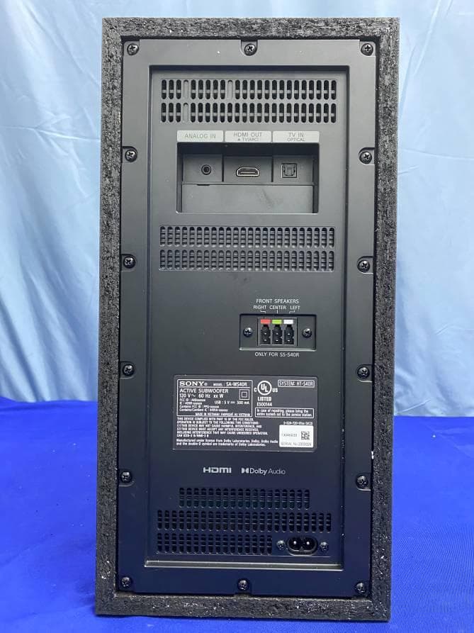
Click to zoom
Application Details
- Equipment Class
- DTS - Digital Transmission System
- Date of Grant
- Dec 28, 2020
- Application Purpose
- Original Equipment
- Date of Application
- Dec 17, 2020
- Equipment Note
- Home Theatre System
- Frequency Range
- 2404.00000000 - 2476.00000000
- Company
- Sony Group Corporation
- Country
- Japan
Documents & Files
Document Text
Text extracted from the exhibit documents filed with the FCC. Open a document above to read the original.
Users Manual
Home Theatre System C:\HT2020\EC1\Data\UC2\5022275111\5022275111HTS40RUC2\00COV-HT- S40RUC2\010COV_UC2.fm masterpage: Cover HT-S40R 5-022-275-11(1) Home Theatre System Système Home Cinema HT-S40R Operating Instructions US Manuel d’instructions FR Manual de instrucciones ES C:\Works\FY21HT_models\EC1\IM\FRES (for_UC2)\5022275111\5022275111HTS40RUC2\00COV-HT- S40RUC2\170BCO_UC2.fm masterpage: BCO 5-022-275-11(1) HT-S40R 5-022-275-11(1) ©2021 Sony Corporation Printed in Vietnam Imprimé au Vietnam When there is a software update available, we will notify you on the following website: https://www.sony.com/am/support Quand une mise à jour du logiciel est disponible, nous vous en aviserons sur le site web suivant : https://www.sony.eu/support Si hay una actualización de software disponible, publicaremos la correspondiente notificación en el siguiente sitio web: https://www.sony.eu/support 2 US HT-S40R 5-022-275-11(1) C:\HT2020\EC1\Data\UC2\5022275111\5022275111HTS40RUC2\01US-HT-S40RUC2\020REG.fm masterpage: Left Owner’s Record The model and serial numbers are located on the rear of the subwoofer. Record the serial numbers in the space provided below. Refer to them whenever you call upon your Sony dealer regarding the Home Theatre System. Model No. HT-S40R Serial No. To reduce the risk of fire or electric shock, do not expose this speaker system to rain or moisture. The speaker system is not disconnected from the mains as long as it is connected to the AC outlet, even if the speaker system itself has been turned off. To reduce the risk of fire, do not cover the ventilation opening of the speaker system with newspapers, tablecloths, curtains, etc. Do not expose the speaker system to naked flame sources (for example, lighted candles). To reduce the risk of fire or electric shock, do not expose this speaker system to dripping or splashing, and do not place objects filled with liquids, such as vases, on the speaker system. As the main plug is used to disconnect the speaker system from the mains, connect the speaker system to an easily accessible AC outlet. Should you notice an abnormality in the speaker system, disconnect the main plug from the AC outlet immediately. Do not install the speaker system in a confined space, such as a bookcase or built-in cabinet. CAUTION Risk of explosion if the battery is replaced by an incorrect type. Do not expose batteries or appliances with battery-installed to excessive heat, such as sunshine and fire. Do not place this product close to medical devices. This product (including accessories) has magnet(s) which may interfere with pacemakers, programmable shunt valves for hydrocephalus treatment, or other medical devices. Do not place this product close to persons who use such medical devices. Consult your doctor before using this product if you use any such medical device. Indoor use only. For the bar speaker and surround speakers The nameplates are located on the bottom of the bar speaker and surround speakers. For the customers in the U.S.A. NOTE: This speaker system has been tested and found to comply with the limits for a Class B digital device, pursuant to Part 15 of the FCC Rules. These limits are designed to provide reasonable protection against harmful interference in a residential installation. This speaker system generates, uses and can radiate radio frequency energy and, if not installed and used in accordance with the instructions, may cause harmful interference to radio communications. However, there is no guarantee that interference will not occur in a particular installation. If this speaker system does cause harmful interference to radio or television reception, which can be determined by turning the speaker system off and on, the user is encouraged to try to correct the interference by one or more of the following measures: WARNING 3 US C:\HT2020\EC1\Data\UC2\5022275111\5022275111HTS40RUC2\01US-HT-S40RUC2\020REG.fm masterpage: Right HT-S40R 5-022-275-11(1) – Reorient or relocate the receiving antenna. – Increase the separation between the speaker system and receiver. – Connect the speaker system into an outlet on a circuit different from that to which the receiver is connected. – Consult the dealer or an experienced radio/TV technician for help. Properly shielded and grounded cables and connectors must be used for connection to host computers and/or peripherals in order to meet FCC emission limits. If you have any questions about this Home Theatre System: Visit: https://www.sony.com/ electronics/support Contact: Sony Customer Information Service Center at 1-800-222-SONY (7669) Write: Sony Customer Information Service Center 12451 Gateway Blvd., Fort Myers, FL 33913 Supplier’s Declaration of Conformity Trade Name: SONY Model No.: HT-S40R Responsible Party: Sony Electronics Inc. Address: 16535 Via Esprillo, San Diego, CA 92127 USA Telephone No.: 858-942-2230 This device complies with Part 15 of the FCC Rules. Operation is subject to the following two conditions: (1) This device may not cause harmful interference, and (2) this device must accept any interference received, including interference that may cause undesired operation. CAUTION You are cautioned that any changes or modifications not expressly approved in this manual could void your authority to operate this speaker system. This speaker system must not be co- located or operated in conjunction with any other antenna or transmitter. This speaker system complies with FCC radiation exposure limits set forth for an uncontrolled environment and meets the FCC radio frequency (RF) Exposure Guidelines. This speaker system should be installed and operated keeping the radiator at least 20cm or more away from person’s body. For the customers in Canada Properly shielded and grounded cables and connectors must be used for connection to host computers and/or peripherals. This speaker system contains licence- exempt transmitter(s)/receiver(s) that comply with Innovation, Science and Economic Development Can…
Text truncated - open the document above for the full version.
Cover Letter(s)
SONY Sony Corporation 1-7-1 Konan Minato-Ku Tokyo, 108-0075 Japan 102920 – 13 Authority to Act as Agent Date: December 3, 2020 American Certification Body, Inc. 6731 Whittier Avenue Suite C110 McLean, VA 22101 To Whom It May Concern: ______ Audix Technology (Shenzhen) Co.,Ltd. ___ is authorized to act on our behalf, until otherwise notified, for applications to American Certification Body, Inc. (ACB). We certify th at we are not subject to denial of federal benefits, that includes FCC benefits, pursuant to Section 5301 of the Anti-Drug Abuse Act of 1988, 21 U.S.C. 862. Further, no party, as defined in 47 CFR 1.2002 (b), to the application is subject t o denial of federal benefits, that i ncludes FCC benefits. We also declare that th e i nformation provided to the FCC is t rue and correct to the best of our knowledge (47 CFR 2.911(d)) and we have been informed of the grantee responsibilities ( 47 CFR 2.909) with regard to certified equipment. Thank you, Agency Agreement Expiration Date: _____2021/2/1_____ By: __________________________ ____ Takeshi Kobayashi______________ (Signature 2 ) (Print name) Title: _ Product Safety Manager _ On be half of: __ Sony Corporation ____________ (Company Name) Telephone: __+81-050-3750-6543________ 1 - If a group “entity” is designated as the authorized agent, the letter of authorization must identify those individuals within the group who are authorized to take action on the application; or alternatively a statement must be provided indicating that as the authorized agent, any individual within the group “entity” is authorized to act on behalf of the applicant / grantee and take action on the application. See https://apps.fcc.gov/oetcf/kdb/forms/FTSSearchResultPage.cfm?switch=P&id=33316 . 2 - Must be signed by applicant contact given for applicant on the FCC site, or by the authorized agent if an appropriate authorized agent letter has been provided. Letters should be placed on appropriate letterhead.
Cover Letter(s)
SONY Sony Corporation 1-7-1 Konan Minato-Ku Tokyo, 108-0075 Japan 102920 – 13 Request for Confidentiality Date: December 3, 2020 Subject: Confidentiality Request for: __AK8SAWS40R and AK8TAS40RWR______ Pursuant to FCC 47 CFR 0.457(d) and 0.459 and IC RSP-100, Section 12.4, the applicant requests t hat a part of the subject FCC application be held confidential. Type of Confidentiality Requested Exhibit ☐Short Term☒PermanentBlock Diagrams ☒Short TermExternal Photos ☒Short Term ☐Permanent Internal Photos ☐Short TermOperation Description/Theory of Operation ☐Short TermTune-Up Procedure ☐Short Term ☒Permanent ☒Permanent Schematics ☒Short TermTest Setup Photos ☒Short Term☐Permanent * 3 User’s Manual ____Sony C orporation ______ has spent substantial effort in developing this product and it is one of the first of its kind in industry. Having the subject information easily available to "competition" would negate the advantage they have achieved by developing this product. Not protecting the details of the design will result in financial hardship. Per manent Confidentiality: The applicant requests the exhibits listed above as permanently confidential be permanently withheld from public review due to materials that contain trade secrets and proprietary information not customarily released to the public. Short-T erm Confidentiality: The applicant requests the exhibits selected above as short term confidential be withheld from public view for a period of ___ 180 ___ days from the date of the Grant of Equipment Authorization and prior to marketing. This is to avoid premature release of sensitive information prior to marketing or release of the product to the public. Applicant is also aware that they are responsible to notify ACB in the event information regarding the product or the product is made available to the public before the requested period has expired. ACB will then release the documents listed above for public disclosure pursuant to FCC Public Notice DA 04-1705. NOT E for Industry Canada Applications: IC currently only distinguishes Permanent Confidentiality exhibits as shown above. Short Term confidentiality is not considered applicable to IC applications. Sin cerely, By: __________________________ __ Takeshi Kobayashi _____ (Signature/Title 4 ) (Print name) 3 - The asterisked items (*) require further information to be provided to ACB before permanent confidentiality will be extended to these exhibits. Please refer to FCC KDB 726920 and the specific Document link for D01 found at: https://apps.fcc.gov/oetcf/kdb/forms/FTSSearchResultPage.cfm?switch=P&id=41731 and review section II, 3) regarding specific information that must accompany these requests. 4 - Must be signed by applicant contact given for applicant on the FCC site, or by the authorized agent if an appropriate authorized agent letter has been provided. Letters should be placed on appropriate letterhead. ☐Permanent
External Photos
AUDIX Technology (Shenzhen) Co., Ltd. Audix Technology (Shenzhen) Co., Ltd. Appendix B Page 1 of 9 Appendix B. Photo of the EUT Figure 1 General Appearance of the EUT Figure 2 General Appearance of the EUT AUDIX Technology (Shenzhen) Co., Ltd. Audix Technology (Shenzhen) Co., Ltd. Appendix B Page 2 of 9 Figure 3 General Appearance of the EUT Figure 4 General Appearance of the EUT AUDIX Technology (Shenzhen) Co., Ltd. Audix Technology (Shenzhen) Co., Ltd. Appendix B Page 3 of 9 Figure 5 General Appearance of the EUT Figure 6 General Appearance of the EUT
ID Label/Location Info
Main label size: W168xH29.5mm Su bwooferl abel size: W92 x H48mm
Internal Photos
AUDIX Technology (Shenzhen) Co., Ltd. Audix Technology (Shenzhen) Co., Ltd. Appendix B Page 4 of 9 Figure 7 Inside of the EUT Figure 8 Inside of the EUT AUDIX Technology (Shenzhen) Co., Ltd. Audix Technology (Shenzhen) Co., Ltd. Appendix B Page 5 of 9 Figure 9 Inside of the EUT Figure 10 Inside of the EUT AUDIX Technology (Shenzhen) Co., Ltd. Audix Technology (Shenzhen) Co., Ltd. Appendix B Page 6 of 9 Figure 11 Inside of the EUT Figure 12 Inside of the EUT AUDIX Technology (Shenzhen) Co., Ltd. Audix Technology (Shenzhen) Co., Ltd. Appendix B Page 7 of 9 Figure 13 Inside of the EUT Figure 14 Inside of the EUT Antenna AUDIX Technology (Shenzhen) Co., Ltd. Audix Technology (Shenzhen) Co., Ltd. Appendix B Page 8 of 9 Figure 15 Inside of the EUT Figure 16 Inside of the EUT AUDIX Technology (Shenzhen) Co., Ltd. Audix Technology (Shenzhen) Co., Ltd. Appendix B Page 9 of 9 Figure 17 Inside of the EUT Figure 18 Inside of the EUT
RF Exposure Info
Audix Technology (Shenzhen) Co., Ltd. Tel: 0755 26639496 No. 6, Kefeng Road, Science & Technology Park, Fax: 0755 26632877 Nanshan District , Shenzhen, Guangdong, China Maximum Permissive Exposure FCC ID: AK8SAWS40R System Name: Home Theatre System [Active Subwoofer: SA-WS40R; Wireless Amplifier: TA-S40RWR] M/N: HT-S40R EUT Name: Active Subwoofer EUT Model No.: SA-WS40R 1. According to FCC CFR 47 §1.1310, the criteria listed in the following table shall be used to evaluate the environmental impact of human exposure to radio frequency (RF) radiation as specified in 1.1307(b). Table 1 Limits for Maximum Permissible Exposure Frequency Range (MHz) Electric Field Strength (V/m) Magnetic Field Strength (A/m) Power Density (mW/cm 2 ) Average Time (Minutes) (A) Limits for Occupational / Control Exposures (f = frequency) 30-300 61.4 0.163 1.0 6 300-1500 --- --- f/300 6 1500-100,000 --- --- 5.0 6 (B) Limits for General Population / Uncontrolled Exposures (f = frequency) 30-300 27.5 0.073 0.2 30 300-1500 --- --- f/1500 30 1500-100,000 --- --- 1.0 30 2. MPE Calculation Sony Corporation declares that the product described above has been evaluated and found to comply with the RF exposure limits for humans, as specified based on ANSI/FCC recommendation. RF Exposure Calculations: S = (P * G) / (4* π * r^2) or r = √(P * G) / (4 * π * S) 2.1. Estimation Result Mode Frequency (MHz) PK Output power (dBm) Output power (mW) antenna Gain (dBi) antenna Gain (linear) MPE (mW/cm 2 ) GFSK (DTS) 2404 5.985 3.967 2.5 1.78 0.001404 2440 6.212 4.180 2.5 1.78 0.001480 2476 6.468 4.434 2.5 1.78 0.001569 Based on safety distance (r) 20cm, the antenna gain (G) is 1.78 Numerical, and the highest power output (P) is 4.434mW, the power density (S) is 0.001569mW/cm 2 .
Test Report
AUDIX Technology (Shenzhen) Co., Ltd. FCC ID:AK8SAWS40R Audix Technology (Shenzhen) Co., Ltd. Report No. ACS-F20249 Page 1 of 50 FCC PART 15C TEST REPORT FOR CERTIFICATION On Behalf of Sony Corporation System Name: Home Theatre System Model No.: HT-S40R Active Subwoofer: SA-WS40R Wireless Amplifier: TA-S40RWR Speaker System: SS-S40R; SS-SS40R EUT Name EUT Model No. Active Subwoofer SA-WS40R FCC ID: AK8SAWS40R Prepared for : Sony Corporation 1-7-1 Konan Minato-ku Tokyo, 108-0075 Japan Prepared By : Audix Technology (Shenzhen) Co., Ltd. No. 6, Kefeng Road, Science & Technology Park, Nanshan District , Shenzhen, Guangdong, China Tel: (0755) 26639496 Report Number : ACS-F20249 Date of Test : Dec.01~05,2020 Date of Report : Dec.17,2020 AUDIX Technology (Shenzhen) Co., Ltd. FCC ID:AK8SAWS40R Audix Technology (Shenzhen) Co., Ltd. Report No. ACS-F20249 Page 2 of 50 TABLE OF CONTENTS Description Page 1. SUMMARY OF STANDARDS AND RESULTS ............................................................. 5 1.1. Description of Standards and Results ..................................................................................... 5 2. GENERAL INFORMATION ............................................................................................. 6 2.1. Description of Equipment Under Test .................................................................................... 6 2.2. Channel list of EUT ................................................................................................................ 7 2.3. Tested Supporting System Details .......................................................................................... 7 2.4. Block diagram of connection between the EUT and simulators ............................................. 7 2.5. Test Facility ............................................................................................................................ 8 2.6. Measurement Uncertainty (95% confidence levels, k=2) ....................................................... 8 3. POWER LINE CONDUCTED EMISSION TEST .......................................................... 9 3.1. Test Equipments ...................................................................................................................... 9 3.2. Block Diagram of Test Setup .................................................................................................. 9 3.3. Power Line Conducted Emission Test Limits......................................................................... 9 3.4. Configuration of EUT on Test ................................................................................................ 9 3.5. Operating Condition of EUT................................................................................................. 10 3.6. Test Procedure ...................................................................................................................... 10 3.7. Power Line Conducted Emission Test Results ..................................................................... 10 4. RADIATED EMISSION TEST ....................................................................................... 13 4.1. Test Equipment ..................................................................................................................... 13 4.2. Block Diagram of Test Setup ................................................................................................ 14 4.3. Radiated Emission Limit ....................................................................................................... 15 4.4. EUT Configuration on Test .................................................................................................. 15 4.5. Operating Condition of EUT................................................................................................. 15 4.6. Test Procedure ...................................................................................................................... 16 4.7. Radiated Emission Test Results ............................................................................................ 16 5. CONDUCTED SPURIOUS EMISSIONS ....................................................................... 32 5.1. Test Equipment ..................................................................................................................... 32 5.2. Block Diagram of Test Setup ................................................................................................ 32 5.3. Limit ...................................................................................................................................... 32 5.4. Test Procedure ...................................................................................................................... 32 5.5. Test result .............................................................................................................................. 32 6. BAND EDGE COMPLIANCE TEST ............................................................................. 35 6.1. Test Equipment ..................................................................................................................... 35 6.2. Limit ...................................................................................................................................... 35 6.3. Test Procedure ....................................................................................................................... 35 6.4. Test Results ........................................................................................................................... 35 7. 6dB & 99% Bandwidth Test ............................................................................................ 40 7.1. Test Equipment ..................................................................................................................... 40 7.2. Block Diagram of Test Setup .............................................................................…
Text truncated - open the document above for the full version.
Test Setup Photos
AUDIX Technology (Shenzhen) Co., Ltd. Audix Technology (Shenzhen) Co., Ltd. Appendix A Page 1 of 2 Appendix A. Photograph of Test A.1 Photos of Power Line Conducted Emission Test A.2 Photos of Conducted Emission Test AUDIX Technology (Shenzhen) Co., Ltd. Audix Technology (Shenzhen) Co., Ltd. Appendix A Page 2 of 2 A.3 Photos of Radiated Emission Test (Above 1000MHz)
Contact Information
Applicant
Kazuyuki Hori(Chief EMC/RF Compliance Specialist)
Technical Contact
AUDIX Technology (Shenzhen) Co., Ltd.Sunny Lu
[email protected]86-755-26639496
No. 6, Kefeng Road, Science & Technology Park, · Shenzhen · China
Non-Technical Contact
AUDIX Technology (Shenzhen) Co., Ltd.Sunny Zhao
[email protected]86-755-26639496
Test Firm
AUDIX Technology (Shenzhen) Co., Ltd.Amelia Peng
Technical Specifications
| # | Rule Parts | Frequency Range | Power Output |
|---|---|---|---|
| 1 | 15C | 2.40 GHz - 2.48 GHz | 4.43 mW |
Other Applications from Sony Group Corporation
AK8WW81782
Aug 21, 2026Radio Equipment
Equipment Class
DSS - Part 15 Spread Spectrum TransmitterAK8CFIZCP2
Aug 03, 2026Wireless Controller
Equipment Class
DSS - Part 15 Spread Spectrum TransmitterAK8OEV321MUH
Apr 14, 2026LCD Monitor
Equipment Class
JAD - Part 15 Class A Digital DeviceAK8OEV431MUH
Apr 14, 2026LCD Monitor
Equipment Class
JAD - Part 15 Class A Digital DeviceAK8OEV271MUH
Apr 14, 2026LCD Monitor
Equipment Class
JAD - Part 15 Class A Digital Device