AK8SFF1
Sony Group Corporation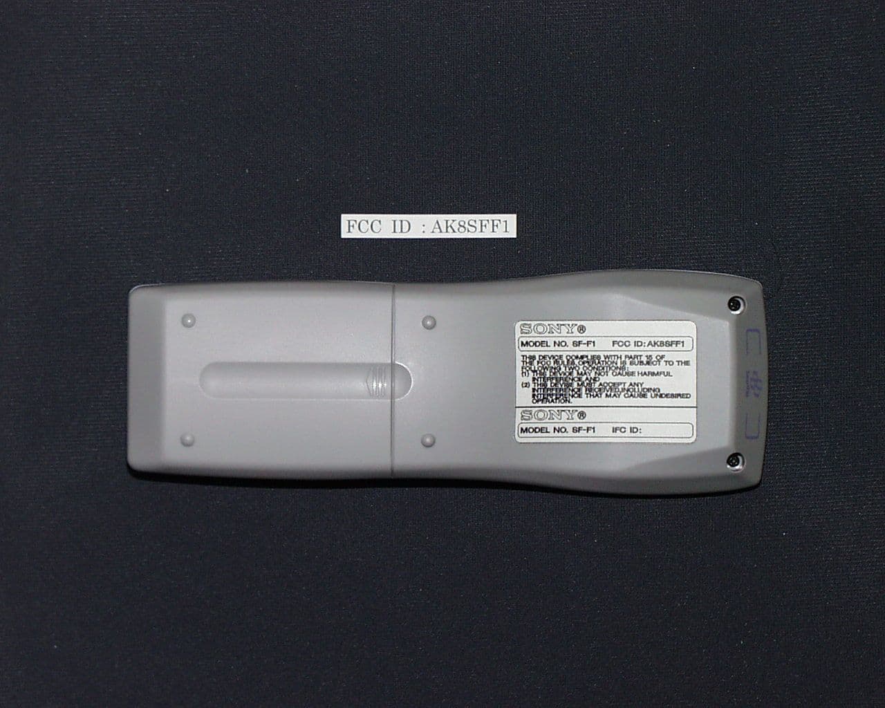
Click to zoom
Application Details
- Equipment Class
- DXX - Part 15 Low Power Communication Device Transmitter
- Date of Grant
- Oct 14, 1999
- Application Purpose
- Original Equipment
- Date of Application
- Aug 22, 1999
- Frequency Range
- 13.56000000 - 13.56000000
- Company
- Sony Group Corporation
- Country
- Japan
Documents & Files
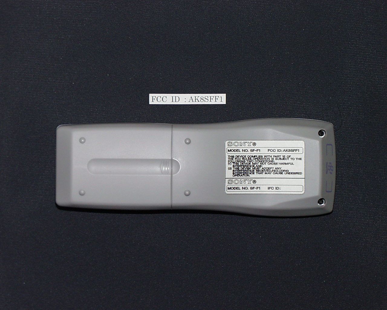
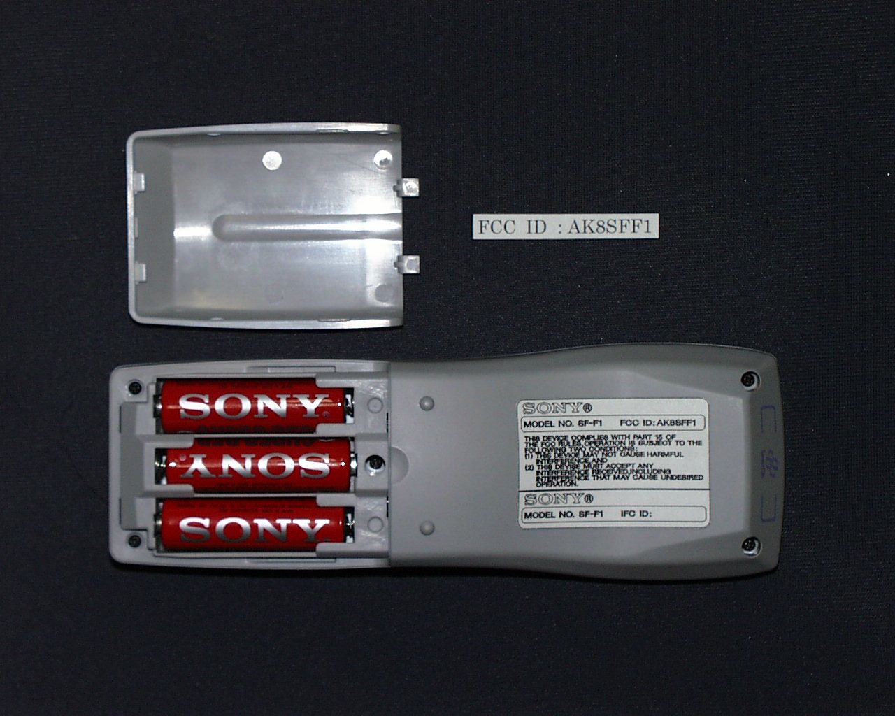
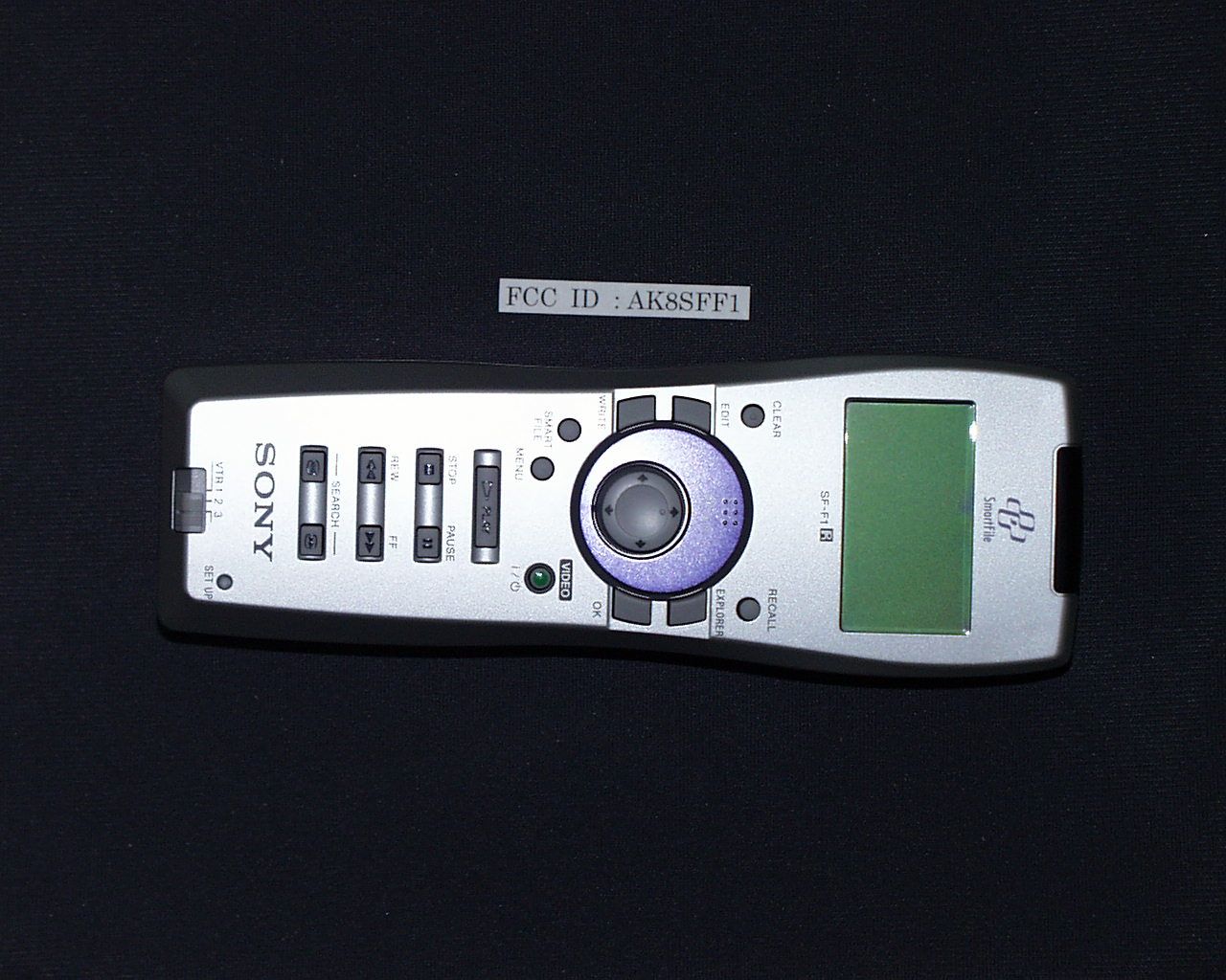

Document Text
Text extracted from the exhibit documents filed with the FCC. Open a document above to read the original.
Block Diagram
FCC 5.5V DC-DC CON. SYSTEM/MODE CONTROL SERIAL BUS CARRIER/DAT A RECEIVER COMPARATOR ANTENNA TRANSMITTER/RECEIVER CONTROL LCD BLOCK CONTROL 5V REG. 5V REG. ON/OFF CONTROL P.W.BOARD A (401RRC-217-01R) P.W.BOARD B (401RRC-218-01R) P.W.BOARD C (401RRC-219-01R) TRANSMITTER DATA IC004 IC008 IC002 X002 8MHz X001 13.56MHz Q005 Q009,Q010 IC006 IC001 IC005 Fig 1 : BLOCK DIAGRAM of SF-F1 3 pieces of size AA (R6) batteries C ID : AK8SFF1 R/DATA KEYS
Operational Description
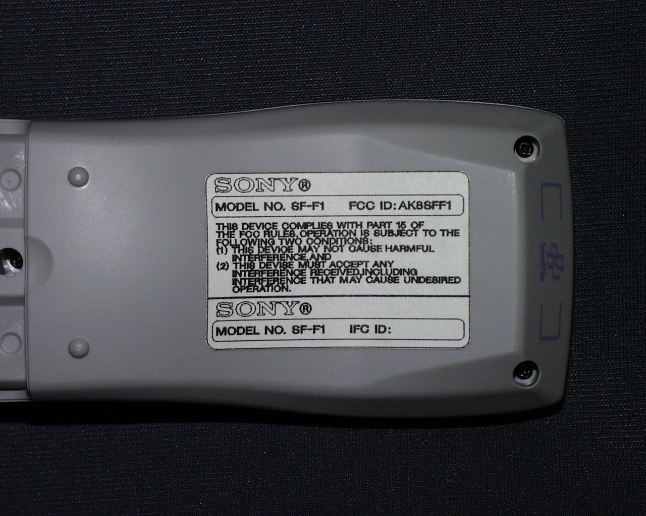
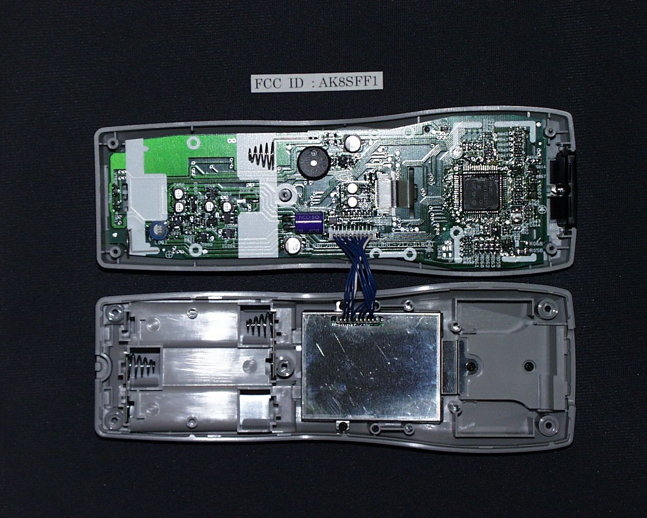
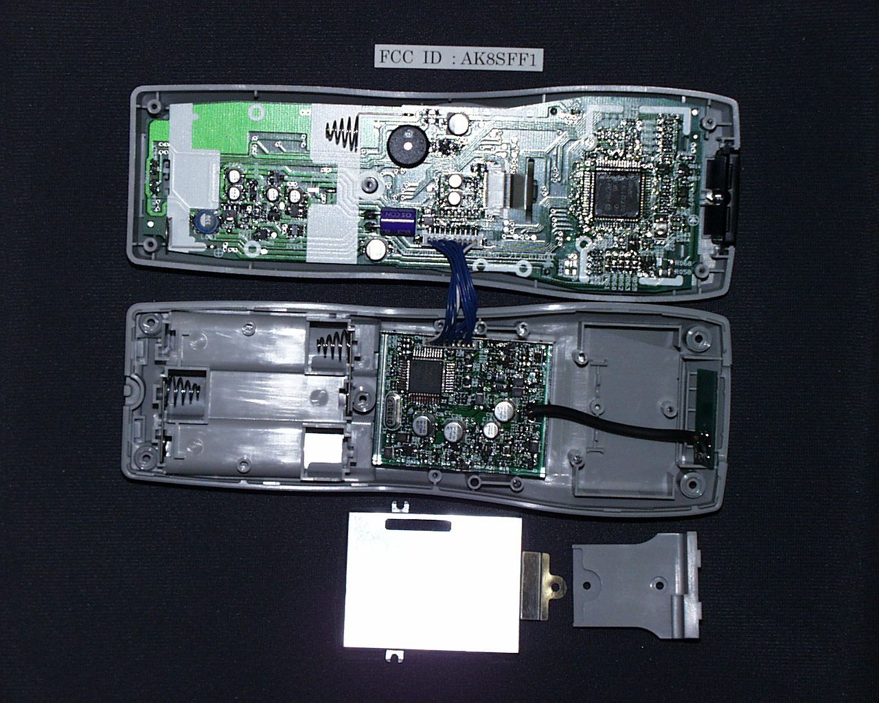
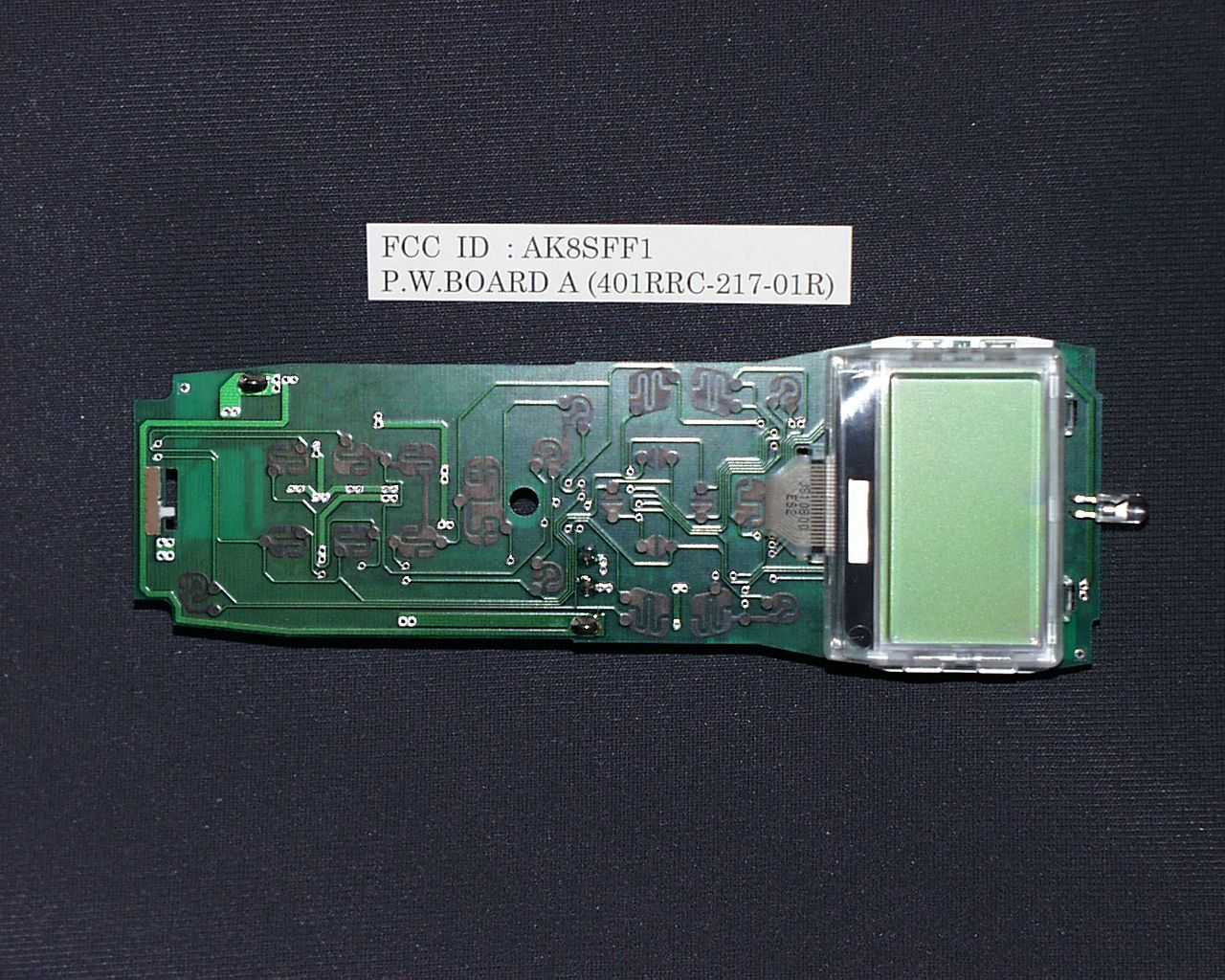
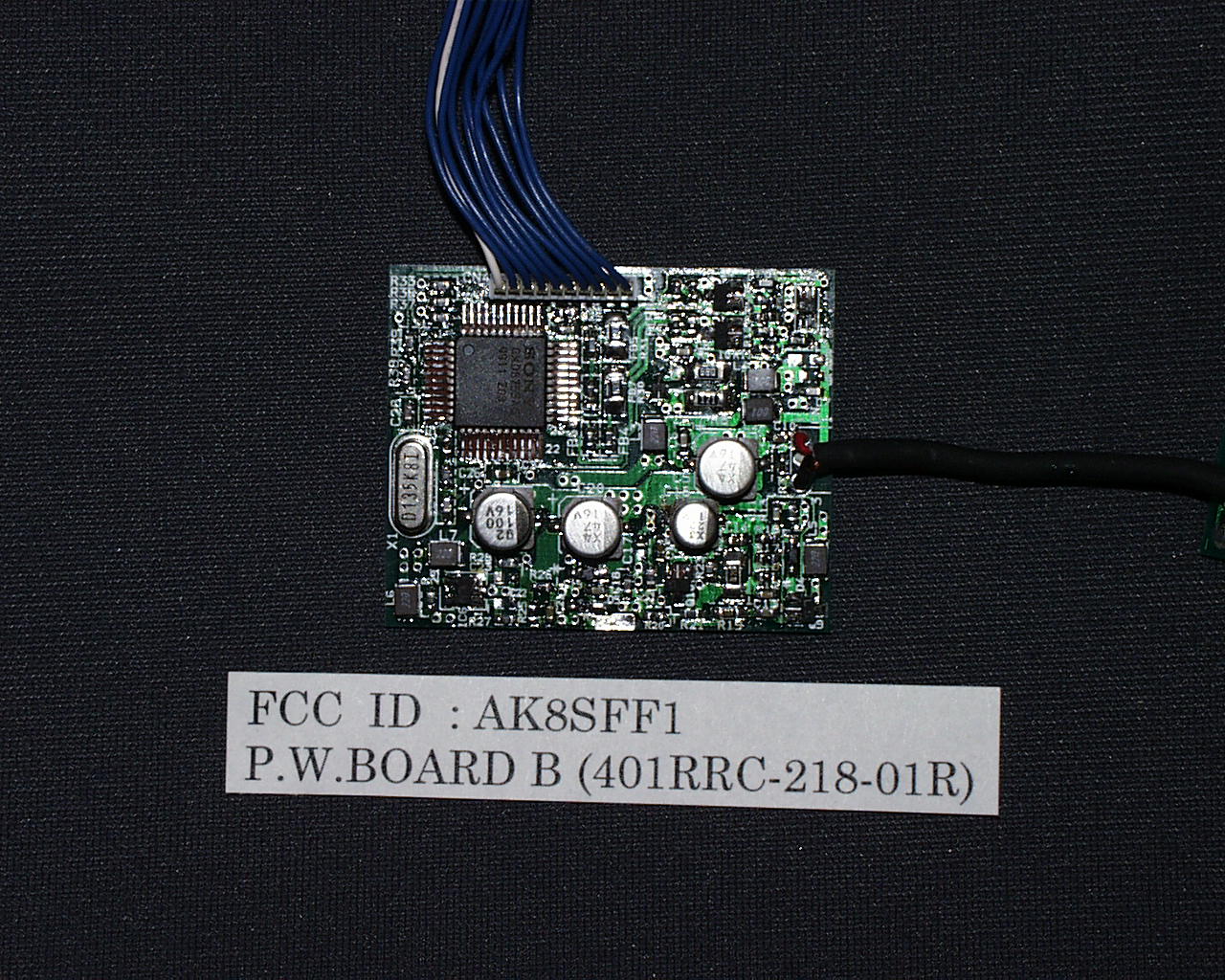
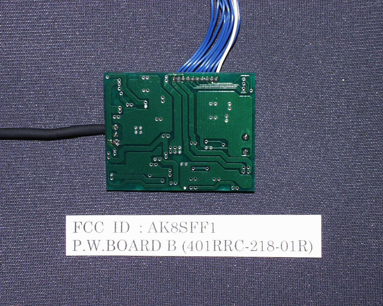
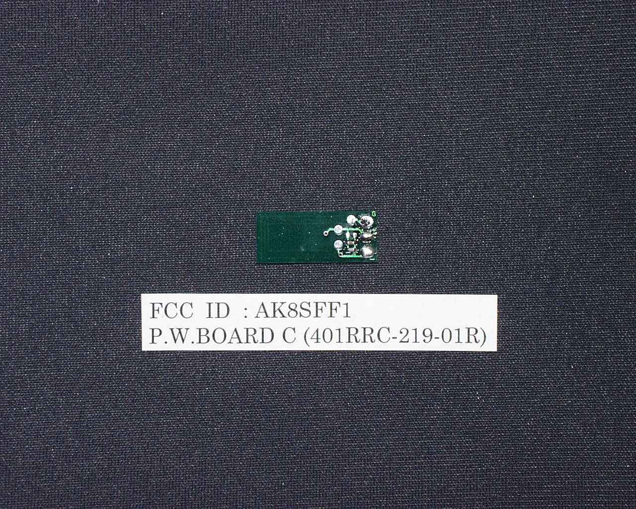
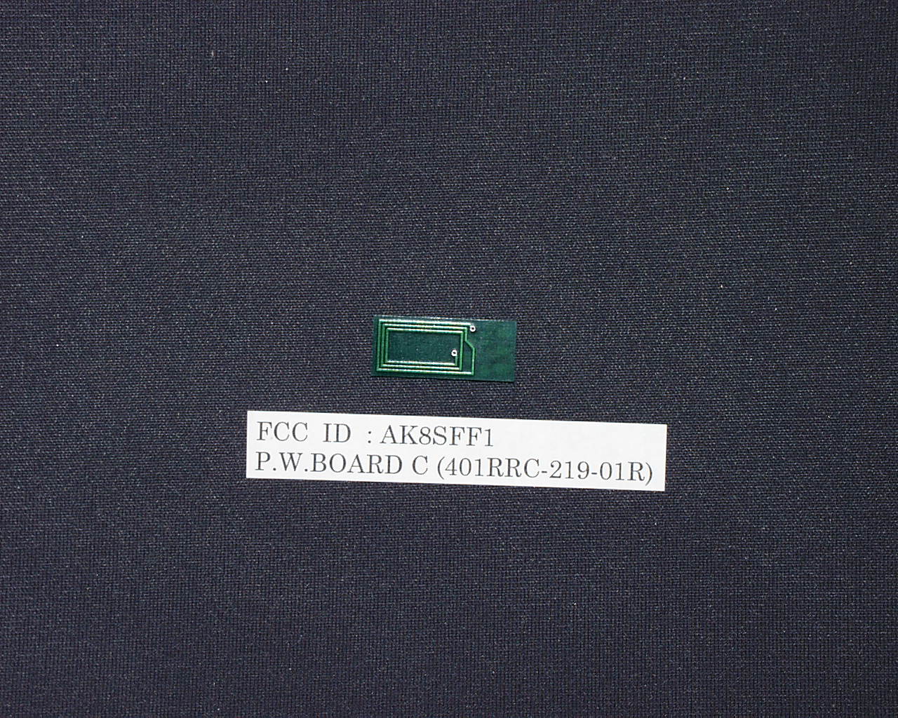
FCC ID : AK8SFF1 Short description of the wireless function named “ SmartFile “ Our “SmartFile “ function operates as follows . *Writing method This method is done when we bring the “ SmartFile Finder “ near the video cassette with “ SmartFile Label “ . The circuit of “Smart File “are on P.W.BORD B (401RRC-218-01R) (refer to the block diagram) . The data ( the title of recording program , recording time or so ) comes to IC001 from IC002 through the synchronous serial bus . Then the data is coded in Manchester method and the carrier (13.56 MHz oscillated in IC001) will be modulated by the data in ASK modulated method in IC001 . Then the modulated carrier will be carried to the transmitter block (on P.W.BOARD B / 401RRC-218-01R) and radiated from the antenna (on P.W.BOARD C / 401RRC-219-01R) . The radiated data and the carrier is caught by the antenna of “Smart File Label” (attached onto the video cassette tape) by electromagnetic mutual coupling . The Logic IC on the “Smart File Label” will be powered by rectifying the received carrier . And the IC starts to write the received data into the EEPROM on the label *Reading method This method is done when we bring the “ SmartFile Finder “ near the video cassette with “ SmartFile Label “ . When the “Smart File Label” is placed near the antenna (on P.W.BOARD C / 401RRC-219- 01R) in the “SmartFile Finder” and push the “READ” button on the “SmartFile Finder” , the antenna on the label will be electromagnetic mutual coupled with the antenna in the “SmartFile Finder” . And the carrier (13.56 MHz) will be caught by the antenna on the label . The Logic IC on the “Smart File Label” will be powered by rectifying the received carrier . And the IC starts to read the data stored in the EEPROM on the “Smart File Label” and if the data exists , its causes the impedance change of the antenna on the label . And the change of the impedance causes the voltage and current change on the antenna in the “SmartFile Finder” through the electromagnetic mutual coupling . The change on the antenna will received as an ASK modulated carrier. And it will be detected by IC006 and the Manchester coded data will be gotten . Then the data is fed to IC001 and decoded in IC001 . Then the decoded data will be sent from IC001 to IC002 through the synchronous serial bus . And then IC002 controls the LCD block to display the contents of the data . So finally we can know the contents of the tape on the LCD display equipped in the “SmartFile Finder” .
Test Report
JAPAN QUALITY ASSURANCE ORGANIZATION 21-25, KINUTA 1-CHOME, SETAGAYA-KU, TOKYO 157-8573 JAPAN PHONE (03) 3416-0111, TELEX 242-2531 JQA J FAX (03) 3416-9691 JQA APPLICATION NO.: 80-90247 Issue Date : August 10, 1999 Page 1 of 29 EMI TEST REPORT JQA APPLICATION NO. : 80-90247 Model No. : SF-F1 Type of Equipment : Smart File Finder Regulations Applied : CFR 47 FCC Rules and Regulations Part 15 FCC ID : AK8SFF1 Applicant : Sony Corporation Address : 6-7-35, Kitashinagawa, Shinagawa-ku Tokyo 141-0001, Japan Manufacture : Sony Corporation Address : 6-7-35, Kitashinagawa, Shinagawa-ku Tokyo 141-0001, Japan Final Judgment : Passed TEST RESULTS IN THIS REPORT are obtained in use of equipment that is traceable to Electrotechnical Lab. of MITI Japan and Communications Research Lab. of MPT Japan. The test results only respond to the tested sample. It is not allowed to copy this report even partly without the allowance of the JQA EMC Engineering Dept. Testing Div. COPY JQA Application No. :80-90247 FCC ID :AK8SFF1 Model No. :SF-F1 Issue Date :August 10, 1999 Standard :CFR 47 FCC Rules Part 15 Page 2 of 29 JAPAN QUALITY ASSURANCE ORGANIZATION TABLE OF CONTENTS Page 1 Documentation 1.1 Test Regulation 3 1.2 General Information 3 1.3 Test Condition 4 – 8 1.4 EUT Modifications 9 1.5 Test results 10 1.6 Summary 11 1.7 Test Configuration / Operation of EUT 12 1.8 Preliminary Test and Test-setup (Drawings) 13 – 18 1.9 EUT Arrangement (Photographs) 19 - 20 2 Test Data 2.1 AC Power Line Conducted Emission 0.45 MHz – 30 MHz N/A 2.2 Radiated Emission (Electric Field)9 kHz – 1000 MHz 21 – 26 2.3 Frequency Stability 27 2.4 Occupied Bandwidth 28 – 29 COPY JQA Application No. :80-90247 FCC ID :AK8SFF1 Model No. :SF-F1 Issue Date :August 10, 1999 Standard :CFR 47 FCC Rules Part 15 Page 3 of 29 JAPAN QUALITY ASSURANCE ORGANIZATION 1 DOCUMENTATION 1.1 TEST REGULATION FCC Rules and Regulations Part 15 Subpart A and C (June 23, 1989) Intentional Radiators Test procedure : AC power line conducted emission, radiated emission, frequency stability and occupied bandwidth tests were performed according to the procedures in ANSI C63.4-1992. 1.2 GENERAL INFORMATION 1.2.1 Test facility : 1) Test Facility located at EMC Engineering Dept. Testing Div. : No.2 and 3 Anechoic Chambers( 3 meters Site ) FCC filing No. : 31040/SIT 1300F2 TSURU EMC Branch: Open Site No.1, No.2, An Anechoic Chamber (3 m and 10 m, on common plane) and a Shielded Room (Date of Listing: March 30,1999) 2) EMC Engineering Dept. Testing Div. and TSURU EMC Branch are recognized under the National Voluntary Laboratory accreditation Program for satisfactory compliance established in title 15, Part 285 Code of Federal Regulations. NVLAP Lab Code : 200189-0 (Effective through : June 30, 2000) NVLAP Lab Code : 200192-0 (Effective through : June 30, 2000) 1.2.2 Description of the Equipment Under Test (EUT) : 1) Type of Equipment : Smart File Finder 2) Product Type : Prototype 3) Category : Low Power Communication Device Transmitter 4) EUT Authorization : Certification 5) FCC ID : AK8SFF1 6) Trade Name : SONY 7) Model No. : SF-F1 8) Operating Frequency Range : 13.56 MHz 9) Highest Frequency Used in the EUT : 13.56 MHz 10) Serial No. : None 11) Date of Manufacture : - 12) Power Rating : DC 4.5V(Battery) 13) EUT Grounding : None 1.2.3 Definitions for symbols used in this test report : x - indicates that the listed condition, standard or equipment is applicable for this report. - indicates that the listed condition, standard or equipment is not applicable for this report. COPY JQA Application No. :80-90247 FCC ID :AK8SFF1 Model No. :SF-F1 Issue Date :August 10, 1999 Standard :CFR 47 FCC Rules Part 15 Page 4 of 29 JAPAN QUALITY ASSURANCE ORGANIZATION 1.3 TEST CONDITION 1.3.1 The measurement of the AC Power Line Conducted Emission - was performed in the following test site. x - was not applicable. Test location : Safety Testing Center EMC Engineering Dept. Testing Div. 21-25, Kinuta 1-chome, Setagaya-ku, Tokyo 157-8573, Japan - Shielded Enclosure - Anechoic Chamber No. 2 (portable Type) Used test instruments : Type Model No. Manufacturer Serial No. Last Cal. Interval - Field Strength Meter ESH-2 Rohde & Schwarz 872280/011 Sep. 1998 1 Year - Field Strength Meter ESH-2 Rohde & Schwarz 880370/016 May 1999 1 Year - Field Strength Meter ESH-3 Rohde & Schwarz 881460/016 May 1999 1 Year - Field Strength Meter ESH-3 Rohde & Schwarz 881460/030 Nov 1999 1 Year - LISN KNW-407 Kyoritsu Electrical 8-833-6 Apr. 1999 1 Year - LISN KNW-407 Kyoritsu Electrical 8-855-2 Apr. 1999 1 Year - LISN KNW-407 Kyoritsu Electrical 8-757-1 Apr. 1999 1 Year - RF Cable 3D-2W Fujikura 155-21-005 Apr. 1999 1 Year - RF Cable 3D-2W Fujikura 155-21-006 Apr. 1999 1 Year COPY JQA Application No. :80-90247 FCC ID :AK8SFF1 Model No. :SF-F1 Issue Date :August 10, 1999 Standard :CFR 47 FCC Rules Part 15 Page 5 of 29 JAPAN QUALITY ASSURANCE ORGANIZATION 1.3.2 The measurement of the Radiated Emission(9 kHz – 30 MHz) x - was performed in the following test site. - was not applicable. Test location : JQA SAFTY TESTING CENTER EMC ENGINEERING DEPT. TSURU EMC BRANCH 2096 Ohhata, Tanbozawa, Tsuru-shi Yamanashi-ken 402-0045, JAPAN - Open Site No. 1 (3, 10 or 30 meters) x - Open Site No. 2 (3, 10 or 30 meters) - Anechoic Chamber(3 or 10 meters) Validation of Site Attenuation : 1) Last Confirmed Date :May, 1999 2) Interval :1 year Used test instruments : Type Model No. Manufacturer Serial No. Last Cal. Interval x - Field Strength Meter ESH3 Rohde & Schwarz 872994/047 May 1999 1 Year - Field Strength Meter ESV Rohde & Schwarz 872148/039 May 1999 1 Year - Field Strength Meter ESVP Rohde & Schwarz 879783/030 May 1999 1 Year - Field Strength Meter ESVP Rohde & Schwarz 881478/004 May 1999 1 Year - Field Strength Meter ESVP Rohde & Schwarz 881478/005 May 1999 1 Year x - Antenna HFH2-Z2 Rohde & Schwarz 879284/14 May 1999 1 Year - Antenna KBA-511A Kyoritsu Electrical 0-201-13 Nov. 1998 1 Year - Antenna KBA-511A Kyoritsu Electrical 0-1…
Text truncated - open the document above for the full version.
Contact Information
Applicant
Kazuyuki Hori(Chief EMC/RF Compliance Specialist)
Technical Contact
Non-Technical Contact
Sony CorporationKazunori Morita
[email protected]+81-3-5769-5293
Technical Specifications
| # | Rule Parts | Frequency Range | Power Output | Emission |
|---|---|---|---|---|
| 1 | 15C | 13.56 MHz - 13.56 MHz | 10.00 mW | 400HA1D |
Other Applications from Sony Group Corporation
AK8WW81782
Aug 21, 2026Radio Equipment
Equipment Class
DSS - Part 15 Spread Spectrum TransmitterAK8CFIZCP2
Aug 03, 2026Wireless Controller
Equipment Class
DSS - Part 15 Spread Spectrum TransmitterAK8OEV321MUH
Apr 14, 2026LCD Monitor
Equipment Class
JAD - Part 15 Class A Digital DeviceAK8OEV431MUH
Apr 14, 2026LCD Monitor
Equipment Class
JAD - Part 15 Class A Digital DeviceAK8OEV271MUH
Apr 14, 2026LCD Monitor
Equipment Class
JAD - Part 15 Class A Digital Device