AK8SLVM11HF
Sony Group Corporation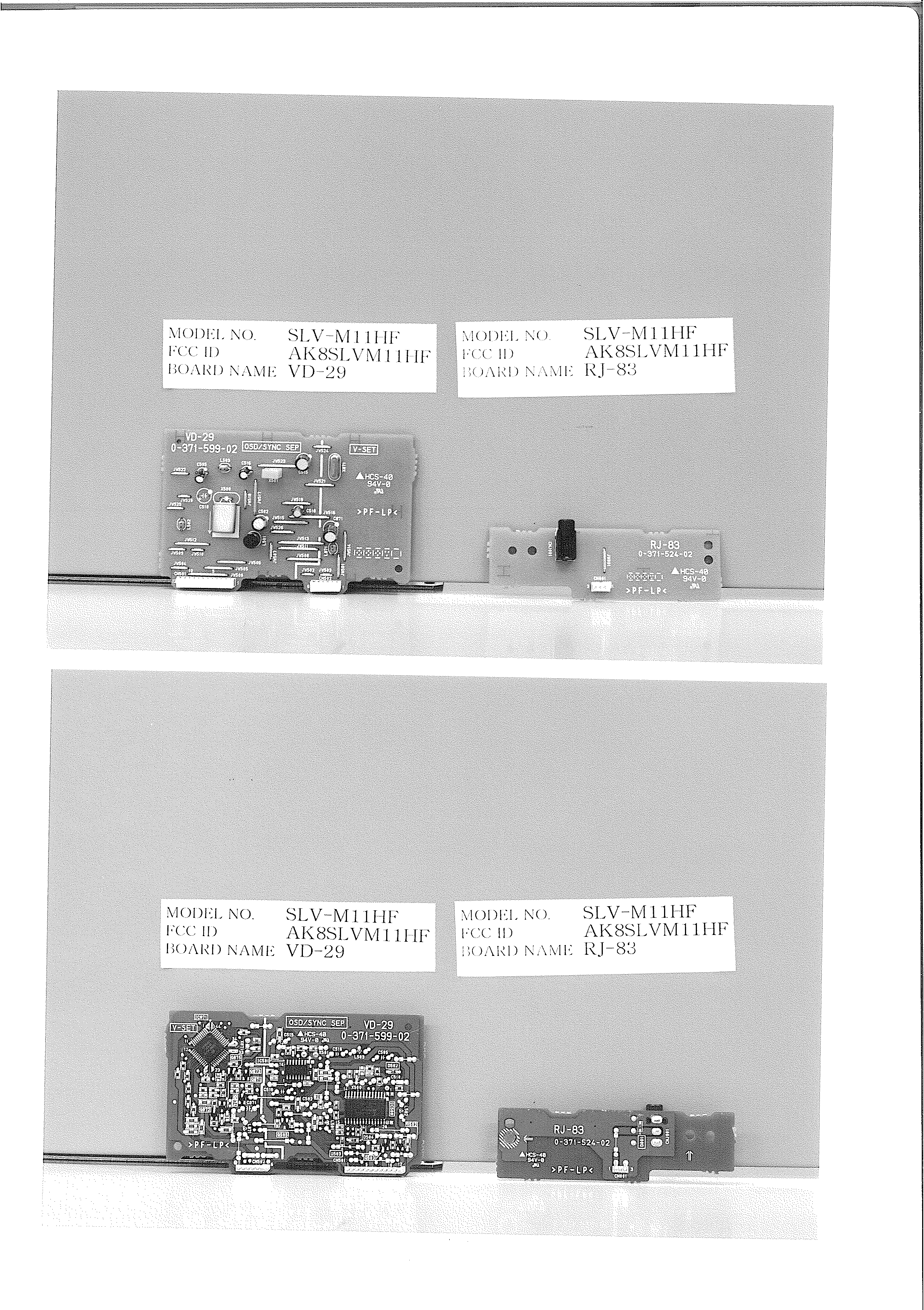
Click to zoom
Application Details
- Equipment Class
- DXX - Part 15 Low Power Communication Device Transmitter
- Date of Grant
- Mar 30, 1999
- Application Purpose
- Original Equipment
- Date of Application
- Mar 01, 1999
- Frequency Range
- 13.56000000 - 13.56000000
- Company
- Sony Group Corporation
- Country
- Japan
Documents & Files
Document Text
Text extracted from the exhibit documents filed with the FCC. Open a document above to read the original.
Users Manual
3-865-760-11(1) Video Cassette Recorder ©1999 by Sony Corporation SLV-M11HF Operating Instructions Owner’s record The model and serial numbers are located at the rear of the unit. Record these numbers in the spaces provided below. Refer to them whenever you call upon your Sony dealer regarding this product. Model No. _________________________ Serial No. _________________________ Declaration of Conformity Trade Name:SONY Model No.:SLV-M11HF Responsible Party: Sony Electronics Inc. Address:1 Sony Drive, Park Ridge, NJ.07656 USA Telephone No.:201-930-6970 This device complies with Part 15 of the FCC Rules. Operation is subject to the following two conditions: (1) This device may not cause harmful interference, and (2) this device must accept any interference received, including interference that may cause undesired operation. For hookup and setup, see the supplied hookup/setup manual. 2 Introduction WARNING To prevent fire or shock hazard, do not expose the unit to rain or moisture. This symbol is intended to alert the user to the presence of uninsulated “dangerous voltage” within the product’s enclosure that may be of sufficient magnitude to constitute a risk of electric shock to persons. This symbol is intended to alert the user to the presence of important operating and maintenance (servicing) instructions in the literature accompanying the appliance. CAUTION To prevent electric shock, do not use this polarized AC plug with an extension cord, receptacle or other outlet unless the blades can be fully inserted to prevent blade exposure. Precautions Safety • Operate the unit only on 120 V AC, 60 Hz. • If anything falls into the cabinet, unplug the unit and have it checked by qualified personnel before operating it any further. • This unit is not disconnected from the AC power source (mains) as long as it is connected to the wall outlet, even if the unit itself has been turned off. • Unplug the unit from the wall outlet if you do not intend to use it for an extended period of time. To disconnect the cord, pull it out by the plug, never by the cord. • One blade of the plug is wider than the other for the purpose of safety and will fit into the power outlet only one way. If you are unable to insert the plug fully into the outlet, contact your Sony dealer. Installing • Allow adequate air circulation to prevent internal heat buildup. • Do not place the unit on surfaces (rugs, blankets, etc.) or near materials (curtains, draperies) that may block the ventilation slots. • Do not install the unit near heat sources such as radiators or air ducts, or in a place subject to direct sunlight, excessive dust, mechanical vibration or shock. • Do not install the unit in an inclined position. It is designed to be operated in a horizontal position only. • Keep the unit and cassettes away from equipment with strong magnets, such as microwave ovens or large loudspeakers. • Do not place heavy objects on the unit. • If the unit is brought directly from a cold to a warm location, moisture may condense inside the VCR and cause damage to the video head and tape. When you first install the unit, or when you move it from a cold to a warm location, wait for about three hours before operating the unit. Information For customers in the USA CAUTION You are cautioned that any changes or modifications not expressly approved in this manual could void your authority to operate this equipment. NOTE: This equipment has been tested and found to comply with the limits for a Class B digital device, pursuant to Part 15 of the FCC Rules. These limits are designed to provide reasonable protection against harmful interference in a residential installation. This equipment generates, uses, and can radiate radio frequency energy and, if not installed and used in accordance with the instructions, may cause harmful interference to radio communications. However, there is no guarantee that interference will not occur in a particular installation. If this equipment does cause harmful interference to radio or television reception, which can be determined by turning the equipment off and on, the user is encouraged to try to correct the interference by one or more of the following measures: • Reorient or relocate the receiving antenna. • Increase the separation between the equipment and receiver. • Connect the equipment into an outlet on a circuit different from that to which the receiver is connected. • Consult the dealer or an experienced radio/ TV technician for help. Caution Television programs, films, video tapes and other materials may be copyrighted. Unauthorized recording of such material may be contrary to the provisions of the copyright laws. Also, use of this recorder with cable television transmission may require authorization from the cable television transmission and/or program owner. 3 Introduction * VCR Plus+, C 3 , ALLSET and PlusCode are trademarks of Gemstar Development Corporation. The VCR Plus+ system is manufactured under license from Gemstar Development Corporation. Table of contents Basic Operations 4Playing a tape 7Recording TV programs 11Locating a channel by Station ID 13Recording TV programs using the VCR Plus+* GOLD system 16Setting the timer manually Additional Operations 20Playing/searching at various speeds 23Creating a favorite channel list with Station ID 26Setting the recording duration time 27Checking/changing/canceling timer settings 29Recording stereo and bilingual programs 31Searching using the index function 32Adjusting the picture 34Changing menu options 37Editing with another VCR SmartFile Function 39About the SmartFile function 41Recording using the SmartFile function 50Selecting and playing a program 52Checking the contents of a tape 53Labeling a recorded program and tape 58Protecting a recorded program 60Erasing the data of an unwanted program 62Registering the contents of a recorded tape in the SmartFile label 64Storing program data from the DIRECTV digital satellite receiver (Program Data Download) …
Text truncated - open the document above for the full version.
Users Manual
3-866-141-11(1) Video Cassette Recorder ©1999 by Sony Corporation SLV-M11HF Hookup/Setup 2 Precautions Safety • Operate the unit only on 120 V AC, 60 Hz. • If anything falls into the cabinet, unplug the unit and have it checked by qualified personnel before operating it any further. • This unit is not disconnected from the AC power source (mains) as long as it is connected to the wall outlet, even if the unit itself has been turned off. • Unplug the unit from the wall outlet if you do not intend to use it for an extended period of time. To disconnect the cord, pull it out by the plug, never by the cord. • One blade of the plug is wider than the other for the purpose of safety and will fit into the power outlet only one way. If you are unable to insert the plug fully into the outlet, contact your Sony dealer. Installing • Allow adequate air circulation to prevent internal heat buildup. • Do not place the unit on surfaces (rugs, blankets, etc.) or near materials (curtains, draperies) that may block the ventilation slots. • Do not install the unit near heat sources such as radiators or air ducts, or in a place subject to direct sunlight, excessive dust, mechanical vibration or shock. • Do not install the unit in an inclined position. It is designed to be operated in a horizontal position only. • Keep the unit and cassettes away from equipment with strong magnets, such as microwave ovens or large loudspeakers. • Do not place heavy objects on the unit. • If the unit is brought directly from a cold to a warm location, moisture may condense inside the VCR and cause damage to the video head and tape. When you first install the unit, or when you move it from a cold to a warm location, wait for about three hours before operating the unit. 3 * VCR Plus+, C 3 , ALLSET and PlusCode are trademarks of Gemstar Development Corporation. The VCR Plus+ system is manufactured under license from Gemstar Development Corporation. Table of contents 4Step 1: Unpacking 5Step 2: Setting up the remote commander 8Step 3: Hookups 9Audio/video (A/V) hookup 11Hookup 1: Using cable box control 15Hookup 2: No cable box, or incompatible cable box with only a few scrambled channels 19Hookup 3: Antenna hookup 23Hookup 4: Incompatible cable box with many scrambled channels 27Hookup 5: DIRECTV digital satellite receiver 30Hookup 6: Incompatible cable box with only a few scrambled channels, using an A/B switch 35Selecting a language 36Setting the clock 42Setting up the cable box control 47Presetting channels 53Setting up the VCR Plus+* GOLD system 59General setup information 61Index to parts and controls back cover Index 4 • Remote commander • Size AA (R6) batteries • Audio/video cable (3-phono, 1-mini to 3-phono, 1-mini) • Monaural cable (1-mini to 1-mini) Step 1 Unpacking Check that you have received the following items with the VCR: • Cable Mouse (cable box controller) • 75-ohm coaxial cable with F-type connectors • SmartFile labels 5 Step 2 Setting up the remote commander Inserting the batteries Insert two size AA (R6) batteries by matching the + and – on the batteries to the diagram inside the battery compartment. Insert the negative (–) end first, then push in and down until the positive (+) end clicks into position. Using the remote commander You can use this remote commander to operate this VCR and a Sony TV or AV receiver. Buttons on the remote commander marked with a dot (•) can be used to operate your Sony TV. The RECEIVER VOL +/– and MUTING buttons can be used to operate your Sony AV receiver. Remote sensor MUTING RECEIVER VOL +/– 123 456 789 0 Set TV RECEIVER / VIDEO to VIDEO and point at the remote sensor on the VCR TV RECEIVER and point at the remote sensor on the TV or AV receiver To operate the VCR a Sony TV or AV receiver TV RECEIVER / VIDEO continued 6 Notes • With normal use, the batteries should last about three to six months. • If you do not use the remote commander for an extended period of time, remove the batteries to avoid possible damage from battery leakage. • Do not use a new battery with an old one. • Do not use different types of batteries. • Some Sony AV receivers may not be operated with the remote commander. Controlling other TVs with the remote commander The remote commander is preprogrammed to control non-Sony TVs. If your TV is listed in the table below, set the appropriate manufacturer’s code number. 1Set TV RECEIVER / VIDEO at the top of the remote commander to ␣TV␣␣RECEIVER . 2Hold down `/1, and enter your TV’s code number(s) using the number buttons. Then release `/1. Now you can use the `/1, VOL +/–, CH +/–, and TV/VIDEO buttons to control your TV. You can also use the buttons marked with a dot (•) to control a Sony TV. To control the VCR, reset TV RECEIVER / VIDEO to VIDEO . Step 2: Setting up the remote commander (continued) 7 Notes • If the TV uses a different remote control system from the one programmed to work with the VCR, you cannot control your TV with the remote commander. • If you enter a new code number, the code number previously entered will be erased. • When you replace the batteries of the remote commander, the code number may change. Set the appropriate code number every time you replace the batteries. • When you press the AUDIO MONITOR button, your TV’s menu may appear on the TV screen. To exit the TV menu, press the MENU button on the TV remote commander or wait until the menu disappears automatically. Code numbers of controllable TVs If more than one code number is listed, try entering them one at a time until you find the one that works with your TV. ManufacturerCode number Sony01 Akai04 AOC04 Centurion12 Coronado03 Curis-Mathes12 Daytron12 Emerson03, 04, 14 Fisher11 General Electric 06, 10 Gold Star03, 04, 17 Hitachi02, 03 J.C.Penny04, 12 ManufacturerCode number JVC09 KMC03 Magnavox03, 08, 12 Marantz04, 13 MGA/Mitsubishi04, 12, 13, 17 NEC04, 12 Panasonic06, 19 Philco03, 04 Philips08 Pioneer16 Portland03 Quasar06, 18 Radio Shack05, 14 ManufacturerCode number RCA04, …
Text truncated - open the document above for the full version.
Block Diagram
FCC ID : AK8SLVM11HF <MA-360> ROTARYVIDEO HEAD CH1 SP IN VHF/UHF CH2 SP OUT CH1 EPCH2 EP X160 16.00MHz CH1 HIFI AUDIO CH2 <VD-29> FULL ERASEAUDIO ERASE <JK-172> NORMAL AUDIO AUDIO L IN 2 R <ML-18> <AN-19> ANTENNA(LARGE)ANTENNA(SMALL) <AN-18> <SRV886UC> 38V 24V/18V TO 13V WALL 6V OUTLET <MECHA DECK> X2023.579545MHz TUNER/RFU/IFBTF-MA431 SYSTEM CONTROL/SERVO/On-SCREEN Display CONTROLCXP88460 VIDEO/NORMAL-AUDIO PROCESSLA71051M VIDEOOUT ON SCREENDISPLAYMB90089PF VIDEOREC/PBLA70011 HIFI AUDIOPROCESS,REC/PBTDA9605H AUDIO VIDEO AUDIO BIAS2SD1620 DRUM MOTOR CAPSTANMOTOR X50014.318MHz TRANS RECT VIDEO AUDIOOUT L R (AUDIO SYNC -SEPLA7218M X501500KHz RECT OSC&SWITCH RECT LINEFILTER X46132.768KHz TIMER/TUNERCONTROLCXP82960 V-SETMC68HC05 X8718.0MHz SMART FILECONTROLCXP84632 X00216.00MHz SMART FILEENCODE & DECODEMODULATOROSCILLATORANTENNA SWITCHCXD8753Q X00113.56MHz SMART FILEDATA DETECTOR X46016.00MHz VIDEOIN 1 AUDIOIN 1 L R -30V <<SLV-M11HF BLO C C K DIAGRAM>>
Operational Description
FCC ID : AK8SLV HF Circuit description for SLV- HF (1/2) TV Recording ; UHF/VHF signal from the antenna is fed to BTF-MA431 (Antenna SW/ RF modulator/TUNER) on MA-360 board, and converted to VIF and SIF , then detected to video and audio signals in BTF-MA431. The video signal is processed in IC201 on MA-360 board , and amplified in IC260 on MA-360 board , then fed to rotary-video head for recording. The audio signal , on the other hand , is processed in IC360 on MA-360 board , and amplified in IC360 on MA-360 board , then fed to rotary-audio head for recording. Video / Audio Signal Recording ; The video signal supplied to the video-in terminal is fed to IC201 on MA- 360 board for signal processing and recording. The audio signal supplied to the audio-in terminal is fed to IC360 on MA- 360 board for signal processing and recording. Playback ; The recording signal picked by the rotary-video head is amplified in IC260 on MA-360 board and processed in IC201 on MA-360 board , then fed to video-out terminal for monitor and BTF-MA431 for modulation. The recorded signal picked by the rotary-audio head is amplified in IC360 on MA-360 board and processed in IC360 on MA-360 board , then fed to audio-out terminal for monitor and BTF-MA431 for modulation. The audio and video signals are modulated by BTF-MA431 then fed to UHF/VHF-out terminal. FCC ID : AK8SLV HF Circuit description for SLV- HF (2/2) Power Supply and Motor Control ; The +B line voltage are produced by the power section employing isolation transformer. Motors are controlled by the system control section consisting of IC101, IC161, etc. on MA-360 board. Smart File ; The circuits of Smart File are on ML-18 board. All processes of Smart File are controlled by IC003. Smart File data is encoded by IC002. Carrier frequency is 13.56MHz that oscillated by IC002. The encoded data is modulated by IC002, then modulated carrier is transmitted from Smart File antenna. The VCR has two antennas. One antenna (large antenna) works against the Smart File label of outside cassette, and the other (small antenna) works against inside cassette. These antenna do not work at the same time. The small antenna works only in a moment when the cassette is put in or put out the VCR, and the large antenna works the other time. The Smart File label is passive, it does not have a battery. It get power by rectifying the receiving carrier, and it write the data to memory. The VCR get the data from Smart File label by changing amplitude caused by changing impedance of Smart File label. The data is detected by IC001, and decoded by IC002. The micro-processor read the decoded data, and display the information of cassette.
Test Report
FCC ID : AK8SLVM11HF REPORT OF MEASUREMENTS Date : February 24, 1999 Issue in : Tokyo, Japan JQA APPLICATION NO.: 80-80868 Applicant : Sony Corporation 7-35, 6-chome, Kitashinagawa, Shinagawa-ku, Tokyo 141-0001, Japan Manufacturer : Sony Corporation 7-35, 6-chome, Kitashinagawa, Shinagawa-ku, Tokyo 141-0001, Japan Description of Equipment : Video Cassette Recorder (Transmitter Portion) FCC ID : AK8SLVM11HF Trade Name : SONY Model No. : SLV-M11HF Operating Frequency : 13.56 MHz Power Supply : 120 VAC 60 Hz Applicable Rule : FCC Rules & Regulations Part 15 Subpart C (June 23, 1989) Place of Measurement : JQA EMC Engineering Dept. Date of Measurement : February 15, 1999(Completed) Total Pages of This Report : 27 (including this page) I certify that I am authorized to sign for the report and that all the statement in this report and in the exhibits hereto are true and correct to the best my knowledge and belief. Shigeru Osawa, Assistant Manager Testing Div. EMC Engineering Dept. FCC ID : AK8SLVM11HF JQA APPLICATION NO.: 80-80868 Sheet 2 of 27 sheets 1. Transmitter Fundamental and Spurious Emission: [§15.225 & §15.209] Measurement Method Employed: Measurements were made under the conditions specified ANSI C63.4. The transmitter under test was operated continuously in its normal operating mode for the purpose of the measurements. In order to secure the continuous operation of the EUT, rewiring in the circuit was done by the manufacturer so as to affect its intended operation. The receiving loop antenna was positioned with its plane vertical at 30 meters from the EUT and rotated about its vertical axis for maximum response at each azimuth about the EUT. The center of the loop antenna was 1 meter above ground. The wooden turntable was rotated 360 degrees to obtain the highest reading on the field strength meter or on the display of the spectrum analyzer. The results were shown the maximum value. Measurement Results: - Internal Large Antenna - Operating Frequency : 13.56 MHz Distance of Measurement : 30 meters Frequency Field Strength (MHz) (dB/mV/m) Fundamental 13.56 < 27.0 Harmonic Frequency 27.12 < 27.0 - Internal Small Antenna - Operating Frequency : 13.56 MHz Distance of Measurement : 30 meters Frequency Field Strength (MHz) (dB/mV/m) Fundamental 13.56 < 27.0 Harmonic Frequency 27.12 < 27.0 FCC ID : AK8SLVM11HF JQA APPLICATION NO.: 80-80868 Sheet 3 of 27 sheets The distance of measurements was reduced to 10 meters. - Internal Large Antenna - Operating Frequency : 13.56 MHz Distance of Measurement : 10 meters Frequency Field Strength (MHz) (dB/mV/m) Fundamental 13.56 40.5 Harmonic Frequency 27.12 < 27.0 - Internal Small Antenna - Operating Frequency : 13.56 MHz Distance of Measurement : 10 meters Frequency Field Strength (MHz) (dB/mV/m) Fundamental 13.56 < 27.0 Harmonic Frequency 27.12 < 27.0 Note: 1. Meter reading value shows field strength, because the value includes antenna factor. 2. The symbol of “<” means “or less”. 3. Measuring Instrument Setting: Detector Function : CISPR Quasi-peak Peak IF Band width : 9 kHz For fundamental, the measured field strength was extrapolated to distance 30 meters, using the formula that field strength varies as the inverse distance square(40 dB per decade of distance). Calculation : 40.5 dB/mV/m – 20log 10 ((30/10) 2 ) = 40.5 – 19.1 = 21.4 dB/mV/m at 30 meters Limits for fundamental(§15.225(a)) = 20log 10 (10000) = 80 dB/mV/m FCC ID : AK8SLVM11HF JQA APPLICATION NO.: 80-80868 Sheet 4 of 27 sheets 2. Radiated Spurious Emission: [§15.209] Measurement Method Employed: Measurements were made under the conditions specified ANSI C63.4. The transmitter under test was operated continuously in its normal operating mode for the purpose of the measurements. In order to secure the continuous operation of the device under test, rewiring in the circuit was done by the manufacturer so as to affect its intended operation. The receiving antenna polarized horizontally was varied from 1 to 4 meters and the wooden turntable was rotated 360 degrees to obtain the highest reading on the field strength meter or on the display of the spectrum analyzer. These measurements were repeated with the receiving antenna polarized vertically. Measurement Results: - Internal Large Antenna - Operating Frequency : 13.56 MHz Distance of Measurement : 3 meters Antenna Meter Reading Results Frequency Factor Horizontal Vertical Horizontal Vertical (MHz) (dB) (dB/mV) (dB/mV) (mV/m) (mV/m) 40.680 2.3 13.0 20.8 5.8 14.3 54.240 5.0 18.6 14.5 15.1 9.4 67.800 7.1 10.3 7.7 7.4 5.5 81.360 8.9 15.7 11.0 17.0 9.9 94.920 10.4 2.9 2.2 4.6 4.3 108.480 11.7 2.6 < -5.0 5.2 < 2.2 122.040 12.9 5.6 -0.8 8.4 4.0 135.600 14.0 13.5 7.5 23.7 11.9 149.160 15.0 14.6 10.6 30.2 19.1 162.720 15.9 15.0 9.0 35.1 17.6 176.280 16.7 6.1 0.5 13.8 7.2 189.840 17.5 10.5 4.1 25.1 12.0 203.400 18.2 2.0 -0.9 10.2 7.3 216.960 18.9 5.7 4.2 17.0 14.3 230.520 19.6 3.3 1.8 14.0 11.7 244.080 20.2 9.7 7.9 31.3 25.4 257.640 20.8 3.8 2.2 17.0 14.1 271.200 21.3 6.4 4.1 24.3 18.6 284.760 21.9 3.4 0.7 18.4 13.5 298.320 22.4 7.7 3.7 32.0 20.2 311.880 22.9 6.0 1.8 27.9 17.2 325.440 23.3 8.8 4.8 40.3 25.4 339.000 23.8 7.8 2.5 38.0 20.7 352.560 24.2 6.4 3.5 33.9 24.3 366.120 24.6 6.2 4.8 34.7 29.5 379.680 25.0 4.0 4.3 28.2 29.2 393.240 25.4 0.9 1.8 20.7 22.9 FCC ID : AK8SLVM11HF JQA APPLICATION NO.: 80-80868 Sheet 5 of 27 sheets Antenna Meter Reading Results Frequency Factor Horizontal Vertical Horizontal Vertical (MHz) (dB) (dB/mV) (dB/mV) (mV/m) (mV/m) 406.800 25.8 1.8 1.7 24.0 23.7 420.360 26.2 3.1 2.0 29.2 25.7 433.920 26.5 3.3 1.7 30.9 25.7 447.480 26.9 -0.4 0.7 21.1 24.0 461.040 27.2 -0.2 0.6 22.4 24.5 474.600 27.5 1.2 0.3 27.2 24.5 488.160 27.9 -0.5 -1.1 23.4 21.9 501.720 28.2 < -5.0 -0.5 < 14.5 24.3 515.280 28.5 < -5.0 < -5.0 < 15.0 < 15.0 528.840 28.9 -0.5 3.3 26.3 40.7 542.400 29.2 < -5.0 -1.7 < 16.2 23.7 555.960 29.5 0.5 4.3 31.6 49.0 569.520 29.9 < -5.0 < -5.0 < 17.6 < 17.6 583.080 30.2 < -5.0 1.0 < 18.2 36.3 596.640 30.5 < -5.0 < -5.0 < …
Text truncated - open the document above for the full version.
Test Setup Photos
FCC ID : AK8SLVM11HF JQA APPLICATION NO.: 80-80868 Sheet 12 of 27 sheets MEASUREMENT SET-UP FOR UP TO 30 MHz Turn Table EUT 10 or 30 m 0.8 m Loop Antenna Field Strength Meter Ground Plane 1.0 m FCC ID : AK8SLVM11HF JQA APPLICATION NO.: 80-80868 Sheet 13 of 27 sheets MEASUREMENT SET-UP FOR RADIATED EMISSIONS Turn Table EUT 3 m 1 m 0.8 m Half-wave Dipole Antenna Field Strength Meter Ground Plane 4 m FCC ID : AK8SLVM11HF JQA APPLICATION NO.: 80-80868 Sheet 14 of 27 sheets Configuration of EUT FCC ID : AK8SLVM11HF JQA APPLICATION NO.: 80-80868 Sheet 15 of 27 sheets 3. Emission Limitation: [§15.231(c)] Measurement Method Employed: By using a spectrum analyzer with a vertical antenna for picking up the signal, the measurements of the fundamental frequency were made under the following transmitting modes of the EUT. Measurements Results : Refer to the attached graphs. FCC ID : AK8SLVM11HF JQA APPLICATION NO.: 80-80868 Sheet 16 of 27 sheets FCC ID : AK8SLVM11HF JQA APPLICATION NO.: 80-80868 Sheet 17 of 27 sheets FCC ID : AK8SLVM11HF JQA APPLICATION NO.: 80-80868 Sheet 18 of 27 sheets MESUREMENT SET-UP FOR BAND WIDTH EUT Approximately 6 inches 0.8 m Spectrum Analyzer Vertical Antenna Test Table FCC ID : AK8SLVM11HF JQA APPLICATION NO.: 80-80868 Sheet 23 of 27 sheets MEASUREMENT SET-UP FOR LINE CONDUCTED RF VOLTAGE EUT 0.4 m 0.8 m Measuring Receiver Table Horizontal Ground Plane Vertical Ground Plane Power Line Filter to AC Power Line LISN FCC ID : AK8SLVM11HF JQA APPLICATION NO.: 80-80868 Sheet 24 of 27 sheets Configuration of EUT FCC ID : AK8SLVM11HF JQA APPLICATION NO.: 80-80868 Sheet 25 of 27 sheets 5. Frequency Stability : [§15.225(c)] Measurement Method Employed: By using frequency counter with suitable RF amplifier, the carrier frequency of the transmitter under test was measured with a temperature variation of –20°C to +50°C at the normal supply voltage, and with a variation in the primary voltage from 85 % to 115 % the rated supply voltage at the temperature of +20°C. Measurement Results : OPERATING FREQUENCY : 13.56 MHz Ambient Temperature Frequency tolerance with time elapse(%) (°C) 0 minute 2 minutes 5 minutes 10 minutes -20 -0.00031 -0.00018 -0.00005 +0.00009 +50 +0.00066 +0.00068 +0.00072 +0.00077 Primary Supply Voltage Frequency tolerance with time elapse(%) (V) 0 minute 2 minutes 5 minutes 10 minutes at 20°C 102 (85%) +0.00060 +0.00060 +0.00060 +0.00061 120 (100%) +0.00060 +0.00060 +0.00060 +0.00061 138 (115%) +0.00060 +0.00060 +0.00060 +0.00061 Specified Limit ±0.01% FCC ID : AK8SLVM11HF JQA APPLICATION NO.: 80-80868 Sheet 26 of 27 sheets MESUREMENT SET-UP FOR FREQUENCY STABILITY TOLERANCE Frequency Counter Vertical Antenna EUT Power Supply with Suitable Amplifier FCC ID : AK8SLVM11HF JQA APPLICATION NO.: 80-80868 Sheet 27 of 27 sheets LIST OF MEASUREMENT EQUIPMENT Equipment (Model No.) Manufacturer Date of Cal. 1. Field Strength Meter ESVP Rohde & Schwarz May 1998 ESH3 Rohde & Schwarz May 1998 2. Spectrum Analyzer 8566B Hewlett Packard April 1998 3. Tuned Dipole Antenna KBA-511 Kyoritsu Electrical Works November 1998 KBA-611 Kyoritsu Electrical Works November 1998 4. Vertical Antenna 91972-2 Stoddard Aircraft Radio - Co., Ltd. 5. LISN KNW-407 Kyoritsu March 1998 6. Frequency Counter 53131A Hewlett Packard June 1998 7. Oven - Ohnishi Co., Ltd. July 1998 8. Loop Antenna HFH2-Z2 Rohde & Schwarz November 1998
Contact Information
Applicant
Kazuyuki Hori(Chief EMC/RF Compliance Specialist)
Technical Contact
Non-Technical Contact
Sony CorporationShinji Yoshimura
[email protected]+81-3-5769-5293
Technical Specifications
| # | Rule Parts | Frequency Range | Power Output | Emission |
|---|---|---|---|---|
| 1 | 15C | 13.56 MHz - 13.56 MHz | 10.00 mW | 400HA1D |
Other Applications from Sony Group Corporation
AK8WW81782
Aug 21, 2026Radio Equipment
Equipment Class
DSS - Part 15 Spread Spectrum TransmitterAK8CFIZCP2
Aug 03, 2026Wireless Controller
Equipment Class
DSS - Part 15 Spread Spectrum TransmitterAK8OEV321MUH
Apr 14, 2026LCD Monitor
Equipment Class
JAD - Part 15 Class A Digital DeviceAK8OEV431MUH
Apr 14, 2026LCD Monitor
Equipment Class
JAD - Part 15 Class A Digital DeviceAK8OEV271MUH
Apr 14, 2026LCD Monitor
Equipment Class
JAD - Part 15 Class A Digital Device