AK8SNCM3WNetwork Camera
Sony Group Corporation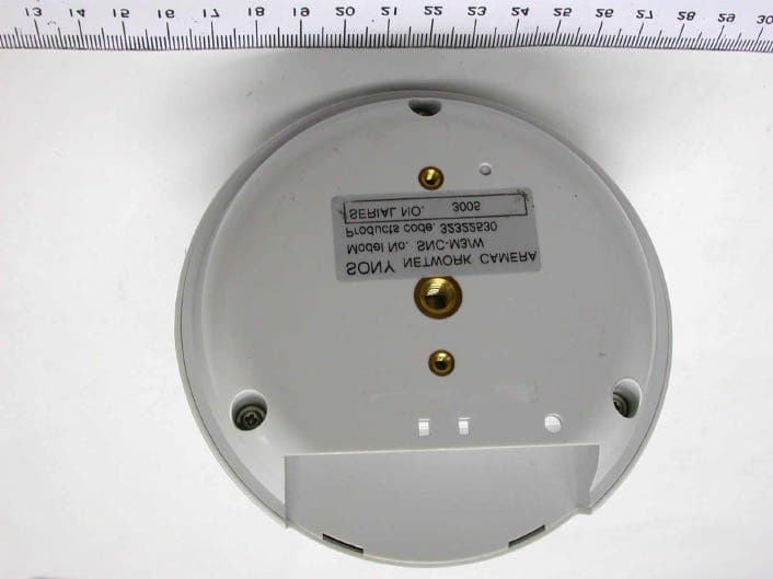
Click to zoom
Application Details
- Equipment Class
- DTS - Digital Transmission System
- Date of Grant
- Nov 25, 2004
- Application Purpose
- Original Equipment
- Date of Application
- Nov 25, 2004
- Equipment Note
- Network Camera
- Frequency Range
- 2412.00000000 - 2462.00000000
- Company
- Sony Group Corporation
- Country
- Japan
Documents & Files
Document Text
Text extracted from the exhibit documents filed with the FCC. Open a document above to read the original.
Users Manual
3-857-708-11 (1) Network Camera © 2004 Sony Corporation SNC-M3/M3W User’s Guide Software Version 1.0 2 O wner's R ec ord The model and serial numbers are located on the bottom. Record the serial number in the space provided below. Refer to these numbers whenever you call upon your Sony dealer regarding this product. Model N o.____________________ Serial N o.____________________ To prevent fire or s hock ha z a rd, do not expos e the unit to ra in or moisture. To avoid elec trica l s hock , do not open the c a binet. R efer s ervicing to qua lified personnel only. A C power adaptor Model N o.:3A -211DA05 (EN G ELECT RI C C O., LTD.) CAU T ION :T his unit is for use only with the supplied AC power adaptor. U se with other AC power adaptors may cause hazards such as a fire. WA R N IN G T his unit has no power switch. Disconnect device of this unit is the mains plug of the AC adaptor. T he mains plug on this equipment must be used to disconnect mains power. Please ensure that the socket outlet is installed near the equipment and shall be easily accessible. I n the event of abnormal operations, disconnect the mains plug. C aution T his installation should be made by a qualified service personnel and should conform to all local codes. C aution T he apparatus shall not be exposed to dripping or splashing and no objects filled with liquid, such as vases, shall be placed on the apparatus. F or cus tomers in the U.S.A . T his equipment has been tested and found to comply with the limits for a Class B digital device, pursuant to Part 15 of the FCC R ules. These limits are designed to provide reasonable protection against harmful interference in a residential installation. T his equipment generates, uses, and can radiate radio frequency energy and, if not installed and used in accordance with the instructions, may cause harmful interference to radio communications. However, there is no guarantee that interference wll not occur in a particular installation. If this equipment does cause harmful interference to radio or television reception, which can be determined by turning the equipment off and on, the user is encouraged to try to correct the interference by one or more of the following measures: –Reorient or relocate the receiving antenna. –Increase the separation between the equipment and receiver. –Connect the equipment into an outlet on a circuit different from that to which the receiver is connected. –Consult the dealer or an experienced radio/TV technician for help. I f you have any questions about this product, you may call: Sony's B usiness I nformation C enter (B I C) at 1-800-686-SON Y (7669) or Write to: Sony C ustomer I nformation Services C enter 6900-29, Daniels Parkway, PMB 330 Fort Myers, Florida 33912 T his device complies with Part 15 of the F CC Rules. Operation is subject to the following two conditions: (1) This device may not cause harmful interference, and (2) this device must accept any interference received, including interference that may cause undesired operation. WA R N IN G Decla ration of C onformity (For S N C -M3 only) Trade Name: SON Y Model N o:SNC-M3 Responsible Party:Sony Electronics Inc. A ddress: 16450 W. Bernardo Dr, San Diego, CA 92127 U .S.A . Telephone N o:858-942-2230 1) To comply with FCC RF exposure compliance requirements, a separation distance of at least 20 cm must be maintained between the antenna of this device and all persons. 2) This transmitter must not be co-located or operating in conjunction with any other antenna or transmitter. C aution 3 You are cautioned that any changes or modifications not expressly approved in this manual could void your authority to operate this equipment. The shielded interface cable recommended in this manual must be used with this equipment in order to comply with the limits for a digital device pursuant to Subpart B of Part 15 of FCC Rules. For customers in Canada This Class B digital apparatus complies with Canadian ICES-003. Operation is subject to the following two conditions: (1) this device may not cause interference, and (2) this device must accept any interference, including interference that may cause undesired operation of the device. The term “IC:” before the radio certification number only signifies that industry Canada technical specifications were met. For customers in Europe Hereby, Sony Corporation, declares that this SNC-M3W is in compliance with the essential requirements and other relevant provisions of the Directive 1999/5/EC. For details, please access the follwing URL: http://www.compliance.sony.de/ ATTENTION The electromagnetic fields at specific frequencies may influence the picture of the unit. Voor de klanten in Nederland • Dit apparaat bevat een vast ingebouwde batterij die niet vervangen hoeft te worden tijdens de levensduur van het apparaat. • Raadpleeg uw leverancier indien de batterij toch vervangen moet worden. De batterij mag alleen vervangen worden door vakbekwaam servicepersoneel. • Gooi de batterij miet weg maar lever deze in als klein chemisch afval (KCA). • Lever het apparaat aan het einde van de levensduur in voor recycling, de batterij zal dan op correcte wijze verwerket worden. NOTICE TO USERS © 2004 Sony Corporation. All rights reserved. This manual or the software described herein, in whole or in part, may not be reproduced, translated or reduced to any machine readable form without prior written approval from Sony Corporation. SONY CORPORATION PROVIDES NO WARRANTY WITH REGARD TO THIS MANUAL, THE SOFTWARE OR OTHER INFORMATION CONTAINED HEREIN AND HEREBY EXPRESSLY DISCLAIMS ANY IMPLIED WARRANTIES OF MERCHANTABILITY OR FITNESS FOR ANY PARTICULAR PURPOSE WITH REGARD TO THIS MANUAL, THE SOFTWARE OR SUCH OTHER INFORMATION. IN NO EVENT SHALL SONY CORPORATION BE LIABLE FOR ANY INCIDENTAL, CONSEQUENTIAL OR SPECIAL DAMAGES, WHETHER BASED ON TORT, CONTRACT, OR OTHERWISE, ARISING OUT OF OR IN CONNECTION WITH THIS MANUAL, THE SOFTWARE OR OTHER INFORMATION CONTAINED HEREIN OR THE USE THE…
Text truncated - open the document above for the full version.
Cover Letter(s)
American Telecommunications Certification Body Inc. 6731 Whittier Ave, McLean, VA 22101 November 14, 2004 RE: FCC ID: AK8SNCM3W_ATCB001855 Attention: Ivy Chen I have a few comments on this Application. Please note that further comments may arise in response to answers provided to the questions below. 1. Please note that while you have provided a block diagram of the overall system, you have not provided the required block diagram of the WLAN transmitter itself. Please provide a block diagram of the WLAN that is in accordance with the requirements of 47CFR2.1033. 2.1033 states that this block diagram must include “the frequency of all oscillators in the device. The signal path and frequency shall be indicated at each block. The tuning range(s) and intermediate frequency(ies) shall be indicated at each block.” 2. Please provide the schematics for the WLAN transmitter. 3. FYI – Please note that the correct ANSI C63.4 version to use is the 2001 version. The 1992 version of ANSI C63.4 is no longer appropriate. Please use the acceptable ANSI C63.4 revision for showing compliance. 4. FYI - Please note that 15.247 radiated spurious limits are average limits. While the device may be claimed to be compliant by comparing a peak reading to the average limit, it is still the average limit that must be met. For example, on page 4 of Test Report 2 you state that 1845MHz is 20.62 dB under the limit. However, while the peak must meet the 74dB limit, in order to show compliance, you must reference the peak to the average limit. This then means that the reading at 1845MHz is not -20.62dB under the limit but is only -0.62dB under the limit (with no average reading the peak must meet the average limit). The report should show compliance to the correct limit. 5. Please note that on page 17 of Test Report 2 the second column heading says dBV. This would be dBvolts. I believe the column heading should be dBuV/m. Please explain and please correct as necessary. 6. Please note that the readings on page 17 of Test Report 2 you have not shown how you derived the final results for the column labeled “level”. Does this reading include any and all transducer factors used in measurement? Are there any unaccounted for factors that were not included. Please also note that 47CFR 2.1033(b)(6) states, “The report shall include sample calculations showing how the measurement results were converted for comparison with the technical requirements.” Please explain and please provide the required formula used either by the engineer or by the software calculating the results. 7. Please note that this device is a mobile rf configuration device and as such requires that the user be informed of rf safety precautions. This is done by a compliance statement in the manual that also informs the user that the device is to be installed to keep a minimum separation distance of 20cm between the user and the antenna. Please include an appropriate rf exposure warning statement in the manual. Dennis Ward mailto:[email protected] The items indicated above must be submitted before processing can continue on the above referenced application. Failure to provide the requested information may result in application termination. Correspondence should be considered part of the permanent submission and may be viewed from the Internet after a Grant of Equipment Authorization is issued. z Page 2 November 14, 2004 Please do not respond to this correspondence using the email reply button. In order for your response to be processed expeditiously, you must submit your documents through the AmericanTCB.com website. Also, please note that partial responses increase processing time and should not be submitted. Any questions about the content of this correspondence should be directed to the sender.
External Photos
External Photos
ID Label/Location Info
SONY MODEL SNC-M3W NETWORK CAMERA DC5V 5.2W Tested to Comply with FCC Part15 Standards 1317 FCC ID: AK8SNCM3W N50 This device complles with Part 16 of the FCC rules. Operation is subject to the following two conditions: (1) This device may not cause harmful interference. (2) This device must acceot any interference recelved Including interference that may cause undesired operation. 004-xxxxxxxxxxx FOR HOME OR OFFICE USE 05NY-xxxxxxxxxxx Sony Corporation Made in Taiwan Canada ID: 409B-SNCM3W RF Module Inside Complies with CANADA RSS-210
Internal Photos
Internal Photos
Operational Description
MB801T CIRCUIT DESCRIPTION HOST MAC BASE BAND TNETW1130 RADIO ANTENNA RF SWITCH CONTROL MAC (Media Access Control) Unit with Baseband Process Unit (U1) The TNETW1130 MAC implements the IEEE Std 802.11 MAC sublayer using both dedicated hardware and embedded firmware. The MAC hardware implements real-time functions, including access protocol management, encryption, decryption, and direct memory access (DMA) transferring of data between the baseband processor and the host. The eCPU runs firmware that manages the flow of commands and data to/from the host, performs scan-and-join operations, and maintains TX and RX queues, as well as a WEP key table stored in internal RAM. The eCPU can override many of the MAC functions that are performed automatically by hardware during normal operation. The baseband processor includes two primary interfaces: radio and MAC. The radio interface provides analog differential signals for transmitting and receiving data by means of 2.4-GHz or 5-GHz radios. The radio interface also includes programmable RX AGC, TX power control, and antenna diversity. The MAC interface ensures that decoded and descrambled RX data is transferred to the MAC for further processing. The MAC interface also allows the MAC to transfer MAC protocol data units (MPDUs) to the baseband processor for encoding and transmission. The baseband processor provides a serial interface through which the MAC accesses registers within the baseband processor core. The baseband processor also provides CCA information to the MAC. RC2422B RF Transceiver Dual-Mode 802.11b/g IQ/IF Transceiver with Dual VCO Synthesizers(U8) The RC2422 is a fully integrated IQ transceiver specifically for use in 802.11 b/g applications. The RC2422 is designed to perform the IQ conversion at 374MHz IF as well as provide an RFLO and control logic to the RFFE (Radio Frequency Front End). The RC2422 also has an internal IQ DC offset calibration function for the receive IQ interface. Combined with the Radia integrated RFFE, the RC2422 completes the Radia WLAN two-chip radio. The RC2422 incorporates all of the system blocks from the modem to the RFFE except for the IF filtering and the reference crystal. The ASIC uniquely incorporates an internal PLL reference oscillator where only a crystal is needed, and also provides a clock output for base-band/MAC ASICs. RC2422 includes two synthesizers with VCOs, IQ modulator, IQ demodulator, anti aliasing filters, IF amplifiers, receive AGC circuit, transmit power control and serial interface. RC2326 Dual-Mode 802.11b/g RFFE ISM band(U2) The RC2326 is a fully integrated Dual Mode Radio Frequency Front End (RFFE) designed specifically for use in 802.11 b/g applications. The RC2326 is designed to perform RF up and down conversions in the unlicensed ISM band. Combined with the Radia RC2422 IF/IQ Tranceiver/Synthesizer, The RC2326 completes the Radia WLAN two-chip radio. The RC2326 incorporates all of the RF blocks for both the “b/g” band except for low cost ceramic filters. The ASIC includes the LNA, PA, mixer, bias circuitry, RX gain control, transmit coupler detector, and T/R switches. High integration and internal RF matching enhances performance and greatly reduce external part count. The only external needed for operation are RF filters and external low power DC switching FETs. Power Regulator(U5,U10,U15) Mini PCI Connector
RF Exposure Info
1.1. Test Result of RF Exposure Evaluation . Product: Network Camera . Test Item: RF Exposure Evaluation Data . Test site: OATSI-SD . Test Mode: Normal Operation 1.1.1. Antenna Gain The maximum Gain is 3.0 dBi. 1.1.2. EUT Operation condition Software provided by client enabled the EUT to transmit and receive data at lowest, middle and highest channel individually. 1.1.3. Output Power into Antenna & RF Exposure Evaluation Distance Modulation Standard: IEEE 802.11b Test Date: Oct. 08, 2004 Temperature: 24 Humidity: 59 Channel Channel Frequency (MHz) Output Power to Antenna (dBm) Power Density (S) (mW/cm 2 ) 01 2412 17.67 0.0232 06 2437 16.84 0.0192 11 2462 16.73 0.0187 The MPE is calculated as 0.0232 mW / cm 2 < limit 1 mW / cm 2 . So, RF exposure limit warning or SAR test are not required.
Test Report
Exclusive Certification Corp. Tel:886-2-2792-3366 Fax:886-2-2792-1100 Issued date: Oct. 14, 2004 1 of 48 FCC ID: AK8SNCM3W FCC Test Report: FI04100202-A FCC TEST REPORT according to FCC Rules and Regulations Part 15 Subpart C † The test result refers exclusively to the test presented test model / sample., † Without written approval of Exclusive Certification Corp. the test report shall not be reproduced except in full. Applicant Sony Corporation Address Gate City Osaki West Tower Osaki East Tec. 1-11-1 Osaki Shinagawa-Ku, Tokyo, 141-0032 Japan Manufacturer Topco corporation Address No.8, Wu-Chung Rd., Wu-Ku industrial Park, Wu-Ku Hsiang, Taipei Hsien 248, Taiwan, R.O.C Equipment Network Camera Model No. SNC-M3W FCC ID AK8SNCM3W Trade Name Sony Exclusive Certification Corp. Tel:886-2-2792-3366 Fax:886-2-2792-1100 Issued date: Oct. 14, 2004 2 of 48 FCC ID: AK8SNCM3W FCC Test Report: FI04100202-A Contents 1. Report of Measurements and Examinations..................................................................................4 1.1. List of Measurements and Examinations............................................................................4 1.2. Antenna Requirements......................................................................................................5 1.3. Test of Conducted Emission..............................................................................................6 1.4. Test of Radiated Emission.................................................................................................8 1.5. 6dB Bandwidth.................................................................................................................9 1.6. Maximum Peak Output Power...........................................................................................9 1.7. Band Edges Measurement..............................................................................................10 1.8. Power Spectral Density...................................................................................................10 1.9. Restricted Bands of Operation..........................................................................................11 1.10. Labeling Requirement......................................................................................................11 1.11. RF Exposure..................................................................................................................12 2. Test Configuration of Equipment under Test................................................................................14 2.1. Test Mode and Test Software...........................................................................................14 2.2. Description of Test System..............................................................................................14 2.3. Connection Diagram of Test System................................................................................14 2.4. Feature of Equipment under Test.....................................................................................15 2.5. RF Module Specifications................................................................................................16 2.6. History of this test report.................................................................................................16 3. General Information of Test.......................................................................................................17 4. Test Result and Data.................................................................................................................18 4.1. Antenna Requirement.....................................................................................................18 4.2. Test Result of Conducted Emission..................................................................................19 4.3. RF Portion......................................................................................................................26 4.4. 6dB Bandwidth Measurement Data..................................................................................32 4.5. Peak Output Power Measurement Data...........................................................................35 4.6. Band Edges Measurement Data......................................................................................38 4.7. Note on Band edge Emission..........................................................................................42 4.8. Power Spectral Density Measurement Data......................................................................45 5. List of Measuring Equipment Used.............................................................................................48 Appendix A. Photographs of EUT........................................................................ ............A1 ~ A10 Exclusive Certification Corp. Tel:886-2-2792-3366 Fax:886-2-2792-1100 Issued date: Oct. 14, 2004 3 of 48 FCC ID: AK8SNCM3W FCC Test Report: FI04100202-A CERTIFICATE OF COMPLIANCE according to FCC Rules and Regulations Part 15 Subpart C Applicant Sony Corporation Address Gate City Osaki West Tower Osaki East Tec. 1-11-1 Osaki Shinagawa-Ku, Tokyo, 141-0032 Japan Manufacturer Topco corporation Address No.8, Wu-Chung Rd., Wu-Ku industrial Park, Wu-Ku Hsiang, Taipei Hsien 248, Taiwan, R.O.C Equipment Network Camera Model No. SNC-M3W FCC ID AK8SNCM3W I HEREBY CERTIFY THAT : The measurements shown in this test report were made in accordance with the procedures given in ANSI C63.4. The equipment was passed the test performed according to FCC Rules and Regulations Part 15 Subpart C (2002). The test was carried out on Oct. 08, 2004 at Exclusive Certification Corp. Signature Anson Chou / Manager Exclusive Certification Corp. Tel:886-2-2792-3366 Fax:886-2-2792-1100 Issued date: Oct. 14, 2004 4 of 48 FCC ID: AK8SNCM3W FCC Test Report: FI04100202-A 1. Report of Measurements and Examinations 1.1. List of Measurements and Examinations FCC Rule . D…
Text truncated - open the document above for the full version.
Test Report
Exclusive Certification Corp. Tel:886-2-2792-3366 Fax:886-2-2792-1100 Issued date: Oct. 14, 2004 26 of 48 FCC ID: AK8SNCM3W FCC Test Report: FI04100202-A 4.3. RF Portion 4.3.1. Test Result of Conducted Emission Exclusive Certification Corp. Tel:886-2-2792-3366 Fax:886-2-2792-1100 Issued date: Oct. 14, 2004 27 of 48 FCC ID: AK8SNCM3W FCC Test Report: FI04100202-A Exclusive Certification Corp. Tel:886-2-2792-3366 Fax:886-2-2792-1100 Issued date: Oct. 14, 2004 28 of 48 FCC ID: AK8SNCM3W FCC Test Report: FI04100202-A 4.3.2. Test Result of Radiated Emission Modulation Standard: IEEE 802.11b a) Emission frequencies below 1 GHz Channel LO Test Date: Oct. 08, 2004 Temperature: 24 Humidity: 59% Frequency (MHz) Ant-Pol H/V Meter Reading (dBuV) Corrected Factor (dB) Result@3m (dBuV/m) Limit@3m (dBuV/m) Margin (dB) Remark Table Deg. Ant High (m) 290.93 H 54.13 -12.56 41.57 46.0 -4.43 Peak 160 1.0 99.84 V 55.77 -17.47 38.30 43.5 -5.20 Peak 130 1.0 124.09 V 55.42 -15.74 39.68 43.5 -3.82 Peak 100 1.0 911.73 V 39.06 3.32 42.38 46.0 -3.62 Peak 155 1.0 936.02 V 38.53 3.96 42.49 46.0 -3.51 Peak 166 1.0 Notes: 1. Result = Meter Reading + Corrected Factor 2. Corrected Factor = Antenna Factor + Cable Loss – Amplifier b) Emission frequencies above 1 GHz Channel LO Frequency (MHz) Ant-Pol H/V Meter Reading (dBuV) Corrected Factor (dB) Result@3m (dBuV/m) Limit@3m (dBuV/m) Margin (dB) Remark Table Deg. Ant High (m) 1840.40 H 57.15 -2.84 54.30 74.0 -19.70 Peak 204 1.5 1840.40 H 42.58 -2.87 39.70 54.0 -14.30 Avg 204 1.5 2038.00 H 58.53 -1.81 56.72 74.0 -17.28 Peak 216 1.5 2038.00 H 50.19 -1.80 48.39 54.0 -5.61 Avg 216 1.5 4823.80 H 52.19 7.22 60.13 74.0 -13.87 Peak 188 1.5 4823.80 H 31.89 7.25 39.14 54.0 -14.86 Avg 188 1.5 2605.50 H 50.63 0.20 50.83 74.0 -23.17 Peak 182 1.5 2033.50 V 53.35 -2.51 50.83 74.0 -23.17 Peak 196 1.5 Exclusive Certification Corp. Tel:886-2-2792-3366 Fax:886-2-2792-1100 Issued date: Oct. 14, 2004 29 of 48 FCC ID: AK8SNCM3W FCC Test Report: FI04100202-A Modulation Standard: IEEE 802.11b a) Emission frequencies below 1 GHz Channel MID Test Date: Oct. 08, 2004 Temperature: 24 Humidity: 59% Frequency (MHz) Ant-Pol H/V Meter Reading (dBuV) Corrected Factor (dB) Result@3m (dBuV/m) Limit@3m (dBuV/m) Margin (dB) Remark Table Deg. Ant High (m) 290.93 H 54.36 -12.56 41.78 46.0 -4.22 Peak 150 1.0 124.09 V 55.46 -15.74 39.72 43.5 -3.78 Peak 120 1.0 935.98 V 38.97 3.96 42.93 46.0 -3.07 Peak 150 1.0 Notes: 1. Result = Meter Reading + Corrected Factor 2. Corrected Factor = Antenna Factor + Cable Loss – Amplifier b) Emission frequencies above 1 GHz Channel MID Frequency (MHz) Ant-Pol H/V Meter Reading (dBuV) Corrected Factor (dB) Result@3m (dBuV/m) Limit@3m (dBuV/m) Margin (dB) Remark Table Deg. Ant High (m) 1845.00 H 56.22 -2.84 53.38 74.00 -20.62 Peak 193 1.5 1845.00 H 43.96 -2.84 41.12 54.00 -12.88 Avg 193 1.5 2053.00 H 54.94 -1.75 53.19 74.00 -20.81 Peak 212 1.5 2053.00 H 42.83 -1.75 41.08 54.00 -12.92 Avg 212 1.5 2605.50 H 50.55 0.20 50.75 74.00 -23.25 Peak 198 1.5 4874.80 H 49.73 7.40 57.14 74.00 -16.86 Peak 200 1.5 4874.80 H 37.05 7.43 44.47 54.00 -9.53 Avg 200 1.5 1845.00 V 54.94 -3.48 51.46 74.00 -22.54 Peak 181 1.5 2063.00 V 56.66 -2.45 54.22 74.00 -19.78 Peak 183 1.5 2063.00 V 48.89 -2.41 46.48 54.00 -7.52 Avg 183 1.5 Exclusive Certification Corp. Tel:886-2-2792-3366 Fax:886-2-2792-1100 Issued date: Oct. 14, 2004 30 of 48 FCC ID: AK8SNCM3W FCC Test Report: FI04100202-A Modulation Standard: IEEE 802.11b a) Emission frequencies below 1 GHz Channel HI Test Date: Oct. 08, 2004 Temperature: 24 Humidity: 59% Frequency (MHz) Ant-Pol H/V Meter Reading (dBuV) Corrected Factor (dB) Result@3m (dBuV/m) Limit@3m (dBuV/m) Margin (dB) Remark Table Deg. Ant High (m) 502.39 H 48.11 -6.22 41.89 46.0 -4.11 Peak 250 1.0 124.09 V 54.99 -15.74 39.25 43.5 -4.25 Peak 100 1.0 911.73 V 38.57 3.32 41.89 46.0 -4.11 Peak 150 1.0 953.98 V 39.63 3.96 43.59 46.0 -2.41 Q.P 115 1.0 Notes: 1. Result = Meter Reading + Corrected Factor 2. Corrected Factor = Antenna Factor + Cable Loss – Amplifier b) Emission frequencies above 1 GHz Channel HI Frequency (MHz) Ant-Pol H/V Meter Reading (dBuV) Corrected Factor (dB) Result@3m (dBuV/m) Limit@3m (dBuV/m) Margin (dB) Remark Table Deg. Ant High (m) 1845.00 H 56.40 -2.84 53.56 74.0 -20.44 Peak 200 1.5 2079.00 H 51.81 -1.66 50.15 74.0 -23.85 Peak 182 1.5 2293.50 H 52.74 -0.92 51.82 74.0 -22.18 Peak 196 1.5 2605.50 H 51.97 0.20 52.18 74.0 -21.82 Peak 201 1.5 4924.40 H 49.11 7.58 56.69 74.0 -17.31 Peak 213 1.5 4924.40 H 33.57 7.60 41.17 54.0 -12.83 Avg 213 1.5 1845.00 V 54.54 -3.48 51.05 74.0 -22.95 Peak 214 1.5 2079.00 V 52.67 -2.36 50.31 74.0 -23.69 Peak 219 1.5 Exclusive Certification Corp. Tel:886-2-2792-3366 Fax:886-2-2792-1100 Issued date: Oct. 14, 2004 31 of 48 FCC ID: AK8SNCM3W FCC Test Report: FI04100202-A 4.3.3. Photographs of Radiated Emission Test FRONT VIEW REAR VIEW Exclusive Certification Corp. Tel:886-2-2792-3366 Fax:886-2-2792-1100 Issued date: Oct. 14, 2004 32 of 48 FCC ID: AK8SNCM3W FCC Test Report: FI04100202-A 4.4. 6dB Bandwidth Measurement Data Modulation Standard: IEEE 802.11b Test Date: Sep. 15, 2004 Temperature: 27 Humidity: 58% a) Channel 01: 6dB Emission Bandwidth is 12.3 MHz b) Channel 06: 6dB Emission Bandwidth is 12.1 MHz c) Channel 11: 6dB Emission Bandwidth is 12.2 MHz Exclusive Certification Corp. Tel:886-2-2792-3366 Fax:886-2-2792-1100 Issued date: Oct. 14, 2004 33 of 48 FCC ID: AK8SNCM3W FCC Test Report: FI04100202-A Exclusive Certification Corp. Tel:886-2-2792-3366 Fax:886-2-2792-1100 Issued date: Oct. 14, 2004 34 of 48 FCC ID: AK8SNCM3W FCC Test Report: FI04100202-A Exclusive Certification Corp. Tel:886-2-2792-3366 Fax:886-2-2792-1100 Issued date: Oct. 14, 2004 35 of 48 FCC ID: AK8SNCM3W FCC Test Report: FI04100202-A 4.5. Peak Output Power Measurement Data Modulation Standard: IEEE 802.11b Test Date: Sep. 15, 2004 Temperature: 27 Humidity: 58% a) Channel 01: Output Peak Power is 17.67 dBm or 58.479 mW b) Channel 06: Output Peak Power is 16.84 dBm or 48.306 …
Text truncated - open the document above for the full version.
Test Setup Photos
Test Setup Photos
Contact Information
Applicant
Kazuyuki Hori(Chief EMC/RF Compliance Specialist)
Technical Contact
Sony Copr.Yuuki Iwasaki
[email protected]813-5-4353-977
Gate City Osaki West Tower Osaki · Tokyo · Japan
Test Firm
Cerpass Technology CorporationAnson Chou
Technical Specifications
| # | Rule Parts | Frequency Range | Power Output |
|---|---|---|---|
| 1 | 15C | 2.41 GHz - 2.46 GHz | 58.00 mW |
Other Applications from Sony Group Corporation
AK8WW81782
Aug 21, 2026Radio Equipment
Equipment Class
DSS - Part 15 Spread Spectrum TransmitterAK8CFIZCP2
Aug 03, 2026Wireless Controller
Equipment Class
DSS - Part 15 Spread Spectrum TransmitterAK8OEV321MUH
Apr 14, 2026LCD Monitor
Equipment Class
JAD - Part 15 Class A Digital DeviceAK8OEV431MUH
Apr 14, 2026LCD Monitor
Equipment Class
JAD - Part 15 Class A Digital DeviceAK8OEV271MUH
Apr 14, 2026LCD Monitor
Equipment Class
JAD - Part 15 Class A Digital Device