AK8TMR5000Wireless Headphone Transmitter
Sony Group Corporation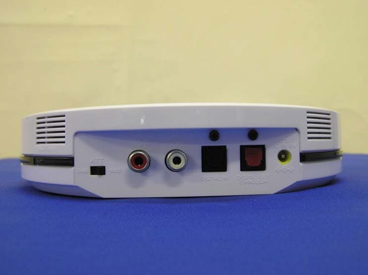
Click to zoom
Application Details
- Equipment Class
- DTS - Digital Transmission System
- Date of Grant
- Dec 15, 2005
- Application Purpose
- Original Equipment
- Date of Application
- Dec 15, 2005
- Equipment Note
- Wireless Headphone Transmitter
- Frequency Range
- 2412.00000000 - 2462.00000000
- Company
- Sony Group Corporation
- Country
- Japan
Documents & Files
Document Text
Text extracted from the exhibit documents filed with the FCC. Open a document above to read the original.
Users Manual
US FR ES Wireless Stereo Headphone System © 2006 Sony Corporation Operating Instructions Mode d’emploi Manual de instrucciones 2-650-249-11(1) MDR-RF5000K 2 US WARNING To reduce the risk of fire or electric shock, do not expose this apparatus to rain or moisture. To avoid electrical shock, do not open the cabinet. Refer servicing to qualified personnel only. For the customers in the USA Owner’s Record The model number is located at the bottom of the transmitter and the left inner side of the headband. The serial number is located at the bottom of the transmitter and the inner side of the battery compartment. Record these numbers in the spaces provided below. Refer to them whenever you call upon your Sony dealer regarding this product. Model No. MDR-RF5000K Transmitter TMR-RF5000 Headphones MDR-RF5000 Serial No. Transmitter Headphones NOTE The transmitter must not be co-located or operated in conjunction with any other antenna or transmitter. The transmitter complies with FCC radiation exposure limits set forth for uncontrolled equipment and meets the FCC radio frequency (RF) Exposure Guidelines in Supplement C to OET65. The transmitter should be installed and operated with at least 20 cm and more between the radiator and person’s body (excluding extremities: hands, wrists, feet and legs). NOTICE FOR THE CUSTOMERS IN THE U.S.A. NOTE This equipment has been tested and found to comply with the limits for a Class B digital device, pursuant to Part 15 of the FCC Rules. These limits are designed to provide reasonable protection against harmful interference in a residential installation. This equipment generates, uses and can radiate radio frequency energy and, if not installed and used in accordance with the instructions, may cause harmful interference to radio communications. However, there is no guarantee that interference will not occur in a particular installation. If this equipment does cause harmful interference to radio or television reception, which can be determined by turning the equipment off and on, the user is encouraged to try to correct the interference by one or more of the following measures: –Reorient or relocate the receiving antenna. –Increase the separation between the equipment and receiver. –Connect the equipment into an outlet on a circuit different from that to which the receiver is connected. –Consult the dealer or an experienced radio/ TV technician for help. You are cautioned that any changes or modifications not expressly approved in this manual could void your authority to operate this equipment. For the customers in the Canada Operation is subject to the following two conditions: (1) this device may not cause interference, and (2) this device must accept any interference, including interference that may cause undesired operation of the device. The transmitter complies with IC radiation exposure limits set forth for uncontrolled equipment and meets RSS-102 of the IC radio frequency (RF) Exposure rules. The transmitter should be installed and operated with at least 20 cm and more between the radiator and person’s body (excluding extremities: hands, wrists, feet and legs). 3 US For the customers in the USA and Canada RECYCLING NICKEL METAL HYDRIDE BATTERIES Nickel Metal Hydride batteries are recyclable. You can help preserve our environment by returning your used rechargeable batteries to the collection and recycling location nearest you. For more information regarding recycling of rechargeable batteries, call toll free 1-800-822-8837, or visit http://www.rbrc.org/ Caution: Do not handle damaged or leaking Nickel Metal Hydride batteries. US Table Of Contents Main Features .............................. 4 Checking the Components and Accessories ................................ 5 Location and Function of Parts ... 6 Front Panel of the Transmitter ..........6 Rear Panel of the Transmitter ............7 Headphone Part Descriptions ...........8 Charging the Supplied Rechargeable Nickel-metal Hydride battery ........................ 9 Inserting the supplied rechargeable nickel-metal hydride battery ......... 9 Charging .............................................10 Checking the battery power ............12 Using the headphones with alkaline batteries (sold separately) ............ 13 Connecting the Headphone System ..................................... 14 Connecting the transmitter to analog components ....................... 14 Connecting the transmitter to digital components ....................... 15 Listening to a Connected Component ............................. 17 Using Additional Headphones .. 21 Replacing the Ear Pads .............. 22 Troubleshooting ......................... 23 Precautions ................................. 27 Specifications ............................. 28 4 US Main Features The MDR-RF5000K is a wireless stereo headphone system using 2.4 GHz wireless digital transmission* 1 . •The MDR-RF5000K is a wireless headphone system using 2.4 GHz wireless digital transmission. •Wireless transmission means you can use these headphones anywhere indoors without worrying about things getting in the way. (Range: Up to approx. 30m)* 2 •Battery is automatically charged by placing the headphones on the transmitter. •Self-adjusting mechanism headband eliminating the need for adjustment. •The number of dedicated headphones (MDR-RF5000, sold separately) can be increased to let more people listen in to the same sound. * 1 “SYNIC Intelligent Wireless” is a trademark of Syncomm Technology Corp. to represent uncompressed digital radio frequency transmission technology. This technology employs a radio frequency carrier, by which audio signals are transmitted with minimum delay and high fidelity. * 2 Transmission distance varies depending on conditions of use. Preparation 5 US Checking the Components and Accessories Before setting up the system, check that all of the components are included. Wireless stereo headphones MDR-RF5000 (1)Transmitter TMR-RF5000 (1) 1 Preparatio…
Text truncated - open the document above for the full version.
External Photos
External Photo Sony Corporation Transmitter (Model: TMR-RF5000) FCC ID: AK8TMR5000 Top Bottom External Photo Sony Corporation Transmitter (Model: TMR-RF5000) FCC ID: AK8TMR5000 Front Back External Photo Sony Corporation Transmitter (Model: TMR-RF5000) FCC ID: AK8TMR5000 Side 1 Side 2
Internal Photos
Internal Photo Sony Corporation Transmitter (Model: TMR-RF5000) FCC ID: AK8TMR5000 TX-RF Unit Over View Internal Photo Sony Corporation Transmitter (Model: TMR-RF5000) FCC ID: AK8TMR5000 TX-RF Unit (Top) TX-RF Unit (Bottom)
Test Report
Test report No. : 26CE0113-HO-3b Page : 1 of 42 Issued date : December 16, 2005 FCC ID : AK8TMR5000 UL Apex Co., Ltd. Head Office EMC Lab. 4383-326 Asama-cho, Ise-shi, Mie-ken 516-0021 JAPAN Telephone : +81 596 24 8116 Facsimile : +81 596 24 8124 MF060b(01.06.05) RADIO TEST REPORT Test Report No. : 26CE0113-HO-3b Applicant : Sony EMCS Corporation Saitama TEC Type of Equipment : Digital Stereo Transmitter Model No. : TMR-RF5000 FCC ID : AK8TMR5000 Test standard : FCC Part 15 Subpart C Section 15.207, Section 15.247 : 2005 Test Result : Complied 1. This test report shall not be reproduced in full or partial, without the written approval of UL Apex Co., Ltd. 2. The results in this report apply only to the sample tested. 3. This equipment is in compliance with the above regulation. We hereby certify that the data contain a true representation of the EMC profile. 4. The test results in this report are traceable to the national or international standards. Date of test: _____________________________ Tested by: ______________________________ ______________________________ Mitsuru Fujimura EMC Services Yutaka Yoshida EMC Services ______________________________ Kenichi Adachi EMC Services Approved by : ______________________________ Naoki Sakamoto Group Leader of EMC Services November 24 to December 3, 2005 Test report No. : 26CE0113-HO-3b Page : 2 of 42 Issued date : December 16, 2005 FCC ID : AK8TMR5000 UL Apex Co., Ltd. Head Office EMC Lab. 4383-326 Asama-cho, Ise-shi, Mie-ken 516-0021 JAPAN Telephone : +81 596 24 8116 Facsimile : +81 596 24 8124 MF060b(01.06.05) CONTENTS PAGE SECTION 1: Client information ............................................................................................................ 3 SECTION 2: Equipment under test (E.U.T.)........................................................................................ 3 SECTION 3: Test specification, procedures & results......................................................................... 4 SECTION 4: Operation of E.U.T. during testing .................................................................................6 SECTION 5: Conducted Emission......................................................................................................... 7 SECTION 6: Spurious Emission ............................................................................................................ 8 SECTION 7: Bandwidth ......................................................................................................................... 8 SECTION 8: Maximum Peak Output Power ....................................................................................... 9 SECTION 9: Peak Power Density.......................................................................................................... 9 APPENDIX 1: Photographs of test setup ............................................................................................ 10 Conducted Emission ............................................................................................................................10 Spurious Emission (Radiated) ............................................................................................................11 APPENDIX 2:Test instruments ............................................................................................................ 12 APPENDIX 3: Data of EMI test............................................................................................................ 13 Conducted Emission ............................................................................................................................13 6dB Bandwidth ....................................................................................................................................16 Maximum Peak OutPut Power...........................................................................................................18 Radiated Spurious Emission...............................................................................................................20 Conducted Spurious Emission............................................................................................................35 Conducted emission Band Edge compliance .....................................................................................38 Power Density ......................................................................................................................................40 99%Occupied Bandwidth ...................................................................................................................42 Test report No. : 26CE0113-HO-3b Page : 3 of 42 Issued date : December 16, 2005 FCC ID : AK8TMR5000 UL Apex Co., Ltd. Head Office EMC Lab. 4383-326 Asama-cho, Ise-shi, Mie-ken 516-0021 JAPAN Telephone : +81 596 24 8116 Facsimile : +81 596 24 8124 MF060b(01.06.05) SECTION 1: Client information Company Name : Sony EMCS Corporation Saitama TEC Brand name : SONY Address : Shinagawa INTERCITY C Tower, 2-15-3 Konan, Minato-ku, Tokyo 108-6201, Japan Telephone Number : +81-3-5769-5640 Facsimile Number : +81-3-5769-5962 Contact Person : Kikuo Murata SECTION 2: Equipment under test (E.U.T.) 2.1 Identification of E.U.T. Type of Equipment : Digital Stereo Transmitter Model No. : TMR-RF5000 Serial No. : 5000130 Country of Manufacture : Malaysia Rating : DC 9V (RF Module DC3.3V) : AC 120V/ 60Hz(AC-S906T) Receipt Date of Sample : November 2, 2005 Condition of EUT : Production Prototype (Not for Sale: This sample is equivalent to mass-produced items.) 2.2 Product Description M/N: TMR-RF5000 is a Digital Stereo Transmitter. Operating frequency : 2412MHz to 2462MHz Bandwidth & Channel spacing : 12MHz & 5MHz Clock frequencies in the system : 44MHz, 12.288MHz (Crystal) Modulation : DSSS, QPSK Antenna Type : Monopole Antenna Antenna Gain : -4 dBi Mode of operation : Simplex ITU Code : G1D FCC 15.31 (e) This EUT provides stable voltage (DC3.3V) constantly to RF…
Text truncated - open the document above for the full version.
Test Setup Photos
Test report No. : 26CE0113-HO-3b Page : 10 of 42 Issued date : December 16, 2005 FCC ID : AK8TMR5000 UL Apex Co., Ltd. Head Office EMC Lab. 4383-326 Asama-cho, Ise-shi, Mie-ken 516-0021 JAPAN Telephone : +81 596 24 8116 Facsimile : +81 596 24 8124 MF060b(01.06.05) APPENDIX 1: Photographs of test setup Conducted Emission Front Rear Test report No. : 26CE0113-HO-3b Page : 11 of 42 Issued date : December 16, 2005 FCC ID : AK8TMR5000 UL Apex Co., Ltd. Head Office EMC Lab. 4383-326 Asama-cho, Ise-shi, Mie-ken 516-0021 JAPAN Telephone : +81 596 24 8116 Facsimile : +81 596 24 8124 MF060b(01.06.05) Spurious Emission (Radiated) Front Rear
Contact Information
Applicant
Kazuyuki Hori(Chief EMC/RF Compliance Specialist)
Technical Contact
UL Apex Co. LtdHironobu Shimoji
[email protected]+81-596-24-8116
4383-326 Asama-cho · Ise-shi, Mie-ken · Japan
Non-Technical Contact
UL Apex Co., LtdKeijiro Kumagai
[email protected]+81-596-24-8116
Test Firm
UL Japan, IncMitsuru Fujimura
Technical Specifications
| # | Rule Parts | Frequency Range | Power Output |
|---|---|---|---|
| 1 | 15C | 2.41 GHz - 2.46 GHz | 25.70 mW |
Other Applications from Sony Group Corporation
AK8WW81782
Aug 21, 2026Radio Equipment
Equipment Class
DSS - Part 15 Spread Spectrum TransmitterAK8CFIZCP2
Aug 03, 2026Wireless Controller
Equipment Class
DSS - Part 15 Spread Spectrum TransmitterAK8OEV321MUH
Apr 14, 2026LCD Monitor
Equipment Class
JAD - Part 15 Class A Digital DeviceAK8OEV431MUH
Apr 14, 2026LCD Monitor
Equipment Class
JAD - Part 15 Class A Digital DeviceAK8OEV271MUH
Apr 14, 2026LCD Monitor
Equipment Class
JAD - Part 15 Class A Digital Device