AK8TMR930Transmitter for Wireless Speakers
Sony Group Corporation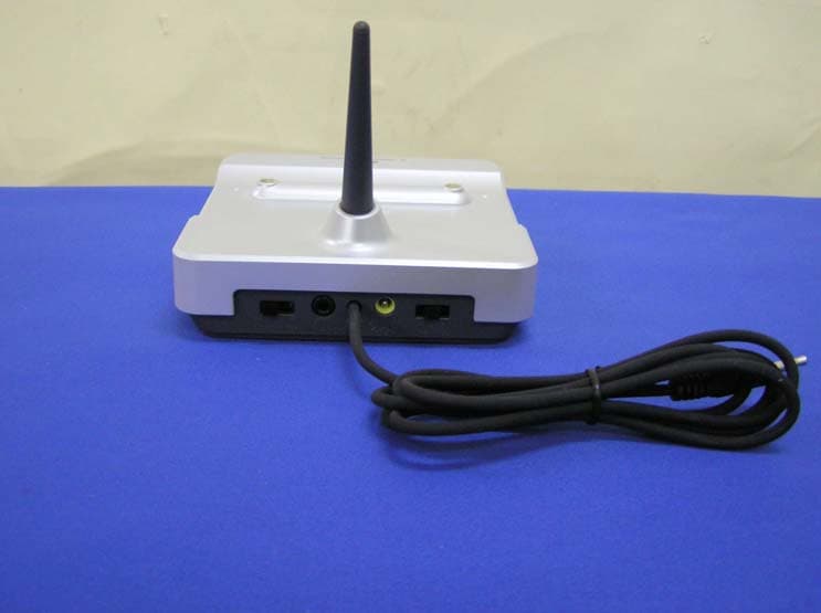
Click to zoom
Application Details
- Equipment Class
- DXX - Part 15 Low Power Communication Device Transmitter
- Date of Grant
- Dec 05, 2005
- Application Purpose
- Original Equipment
- Date of Application
- Dec 05, 2005
- Equipment Note
- Transmitter for Wireless Speakers
- Frequency Range
- 913.50000000 - 914.50000000
- Company
- Sony Group Corporation
- Country
- Japan
Documents & Files
Document Text
Text extracted from the exhibit documents filed with the FCC. Open a document above to read the original.
Users Manual
B DC IN 9VOFFON1 2 3 CHANNELAUDIO INNOISE FILTER A B DC IN 9VOFFON1 2 3 CHANNELAUDIO INNOISE FILTER A 2Open the cabinet of the speaker system and remove the rechargeable battery as illustrated. N Additional information Precautions Notes on the AC power adaptor •Plug the AC power adaptor into a nearby AC output. In case of a problem, unplug from the AC outlet immediately. •Do not place the AC power adaptor on a bookshelf or in a confined place such as a cabinet. •Do not use the AC power adaptor in a place subject to liquid or moisture to avoid fire or electric shock. Furthermore, do not place liquid- filled vessels, such as a vase, etc., on the AC power adaptor. •When the transmitter is not to be used for a long period of time, disconnect the AC power adaptor from the AC outlet holding the plug. Do not pull on the cord. Notes on the location you set the speaker system •Do not leave the wireless speaker system in a location subject to: –Direct sunlight or extremely high temperature such as near a heater or in a car with its windows closed. –High humidity such as in a bathroom. –Excessive dust or sandy places. •The speaker system is magnetically shielded, but do not put a recorded tape, watch, cash card or floppy disk in front of the speaker system. •Set up the speaker system on a flat surface. Notes on charging the battery •When you charge the rechargeable battery, use the supplied transmitter only. •The charging time differs depending on usage conditions of the battery. •When you use the battery for the first time or the battery has not been used for a long time, the battery duration time may become shorter than the usual duration time. However, after you charge the battery several times, the battery duration time returns to its normal condition. •If the battery duration time becomes half of its normal time even after the battery is charged fully, the battery is worn out. In this case, consult your nearest Sony dealer. Notes on using the speaker system •Do not disassemble the speaker unit, built-in amplifier or cabinet. •Do not insert an object into the jack. Doing so may cause a malfunction. •Keep the volume at a moderate level to prevent distortion. •Do not touch the contact points of the transmitter or the contact pins of the speaker system with any metal object, otherwise a short circuit may occur. •If the contact points or the contact pins are dirty, charging may not occur. Clean them regularly with a soft cloth, etc., taking care not to damage the contact pins. Note on cleaning Clean the cabinet of the speaker system with a soft cloth slightly moistened with water or a mild detergent solution. Do not use any type of abrasive pad, scouring powder or solvent such as alcohol or benzene as it may mar the finish of the cabinet. When the color of your monitor screen becomes irregular Because this speaker system is magnetically shielded, you can set it up near a monitor. But depending on the model of the monitor, color irregularity may occur. To correct the color irregular Turn off the monitor, and then turn it on again after 15 to 30 minutes. If color irregularity remains after performing the above •Separate the monitor and the speaker system. •Make sure that no magnetic object, such as may be attached to a door of shelf, healthcare device or toys, etc., is located near the speaker system. If you have any questions or problems concerning the system that are not covered in this manual, please consult your nearest Sony dealer. Be sure to bring the speaker system and the transmitter to the Sony dealer when requiring repair work. Troubleshooting No sound/Muffled sound ,Check the connection of the audio/video equipment. ,Check that the audio/video equipment is turned on. ,Turn up the volume on the connected audio/ video equipment, if the transmitter is connected to the headphones jack. ,Change the radio frequency with the CHANNEL selector on the transmitter, then adjust the TUNE dial again. ,No sound is heard by wireless transmission. •If a cord is connected to the AUDIO IN jack of the speaker system, no sound is heard by wireless transmission. Disconnect the cord from the AUDIO IN jack first, and use the TUNE dial to adjust the tuning of the speaker system until sound is heard. ,The speaker system’s POWER indicator light is turned off. •Turn on the POWER switch, and turn it off, then turn it on again. •Charge the built-in rechargeable battery or if the POWER indicator is still off after charging the built-in rechargeable battery, take the speaker system to a Sony dealer for replacement of the rechargeable battery. ,If you connect the transmitter to the LINE OUT or REC OUT jack of an audio reproducer, make sure that the NOISE FILTER switch is set to OFF. ,Make sure that the NOISE FILTER switch is set to either ON or OFF. (If the switch gets stuck between ON and OFF, the sound will be cut off.) Distortion ,If the transmitter is connected to the headphones jack, turn down the volume of the connected audio/video equipment. If the connected audio/ video equipment has BASS BOOST function, set its function to OFF. ,If the connected audio/video equipment has a LINE OUT jack, connect its LINE OUT jack. ,Change the radio frequency with the CHANNEL selector on the transmitter, then adjust the TUNE dial again. ,The speaker system’s POWER indicator light is turned off. •Turn on the POWER switch, and turn it off, then turn it on again. •Charge the built-in rechargeable battery or if the POWER indicator is still off after charging the built-in rechargeable battery, take the speaker system to a Sony dealer for replacement of the rechargeable battery. ,If you connect the transmitter to LINE OUT or REC OUT jack of an audio reproducer, make sure that the NOISE FILTER switch is set to OFF. Loud background noise ,Move closer to the transmitter. As you move away from the transmitter, more noise is likely to be heard. ,If the transmitter is connected to the headphones jack, turn up the volume of the connected audio…
Text truncated - open the document above for the full version.
External Photos
External Photo Sony Corporation Transmitter (Model: TMR-RF930) FCC ID: AK8TMR930 Top Bottom External Photo Sony Corporation Transmitter (Model: TMR-RF930) FCC ID: AK8TMR930 Front Back External Photo Sony Corporation Transmitter (Model: TMR-RF930) FCC ID: AK8TMR930 Side 1 Side 2
ID Label/Location Info
Internal Photo Sony Corporation Transmitter (Model: TMR-RF930) FCC ID: AK8TMR930 Over View VCO Unit Internal Photo Sony Corporation Transmitter (Model: TMR-RF930) FCC ID: AK8TMR930 VCO Unit (Top) VCO Unit (Bottom)
Internal Photos
Internal Photo Sony Corporation Transmitter (Model: TMR-RF930) FCC ID: AK8TMR930 Over View VCO Unit Internal Photo Sony Corporation Transmitter (Model: TMR-RF930) FCC ID: AK8TMR930 VCO Unit (Top) VCO Unit (Bottom)
Test Report
FCC ID : AK8TMR930 Test report No. : 26CE0272-YK-1 Page : 1 of 22 Issued date : November 18, 2005 UL Apex Co., Ltd. YAMAKITA EMC LAB. 907 Kawanishi, Yamakita-machi, Ashigarakami-gun, Kanagawa-ken, 258-0124 JAPAN Telephone: +81 465 77 1011 Facsimile: +81 465 77 2112 MF060b(01.06.05) EMI TEST REPORT Test Report No. : 26CE0272-YK-1 Applicant : Sony EMCS Corporation Saitama TEC Type of Equipment : Transmitter Model No. : TMR-RF930 FCC ID : AK8TMR930 Test Standard : FCC Part15 Subpart C, Section 15.207, Section 15.215, Section 15.249: 2005 Test Result : Complied 1. This test report shall not be reproduced except in full, without the written approval of UL Apex Co., Ltd. 2. The results in this report apply only to the sample tested. 3. This equipment is in compliance with above regulation. We hereby certify that the data contain a true representation of the EMC profile. 4. The test results in this test report are traceable to the national or international standards. Date of test: November 7 and 15, 2005 Tested by: Takahiro Suzuki & Toyokazu Imamura Approved by: Osamu Watatani Site Manager of Yamakita EMC Lab. FCC ID : AK8TMR930 Test report No. : 26CE0272-YK-1 Page : 2 of 22 Issued date : November 18, 2005 UL Apex Co., Ltd. YAMAKITA EMC LAB. 907 Kawanishi, Yamakita-machi, Ashigarakami-gun, Kanagawa-ken, 258-0124 JAPAN Telephone: +81 465 77 1011 Facsimile: +81 465 77 2112 MF060b(01.06.05) Table of Contents Page 1 Applicant Information 3 2 Product Description 3 3 Test Specification, Procedures and Results 4 4 System Test Configuration 6 5 Conducted Emissions 8 6 Radiated Emissions 9 7 20dB Bandwidth 10 Contents of Appendixes 11 APPENDIX 1: Photographs of test setup 12 APPENDIX 2: Test Data 14 APPENDIX 3: Test instruments 22 FCC ID : AK8TMR930 Test report No. : 26CE0272-YK-1 Page : 3 of 22 Issued date : November 18, 2005 UL Apex Co., Ltd. YAMAKITA EMC LAB. 907 Kawanishi, Yamakita-machi, Ashigarakami-gun, Kanagawa-ken, 258-0124 JAPAN Telephone: +81 465 77 1011 Facsimile: +81 465 77 2112 MF060b(01.06.05) 1 Applicant Information Company Name : Sony EMCS Corporation Saitama TEC Address : Shinagawa INTERCITY C Tower Shinagawa Tec. 2-15-3 Konan Minato-ku, Tokyo, 108-6201 JAPAN Telephone Number : +81-3-5769-5640 Facsimile Number : +81-3-5769-5962 Contact Person : Kikuo Murata 2 Product Description Type of Equipment : Transmitter Model No. : TMR-RF930 Serial No. : 2020355 Rating : : DC9V (AC120V/60Hz) Country of Manufacture : Malaysia Receipt Date of Sample : November 7, 2005 Condition of EUT : Engineering prototype (Not for Sale: This sample is equivalent to mass-produced items.) Model: TMR-RF930 (referred to as the EUT in this report) is a Transmitter of Wireless Speaker System SRS-RF930RK. Frequency of operation : 913.5 – 914.5 MHz Type of modulation : FM Antenna type : Integral antenna Antenna connector type : None Mode of operation : Simplex Emission designation : F8E Operation temperature range: 0 ~ 40 deg. C. *FCC Part15.31 (e) The transmitter provides the module with stable power supply (DC9V), and the power is not changed when voltage of the transmitter is varied. Therefore, the equipment complies power supply regulation. *FCC Part15.203 The transmitter and its antenna comply with this requirement since this antenna is built in the equipment and it cannot be replaced by end users. FCC ID : AK8TMR930 Test report No. : 26CE0272-YK-1 Page : 4 of 22 Issued date : November 18, 2005 UL Apex Co., Ltd. YAMAKITA EMC LAB. 907 Kawanishi, Yamakita-machi, Ashigarakami-gun, Kanagawa-ken, 258-0124 JAPAN Telephone: +81 465 77 1011 Facsimile: +81 465 77 2112 MF060b(01.06.05) 3 Test Specification, Procedures and Results 3.1 Test specification Test specification : FCC Part15 Subpart C: 2005 Title : FCC 47CFR Part15 Radio Frequency Device Subpart C Intentional Radiators Section 15.207 Conducted limits Section 15.215 Additional provisions to the general radiated emission limitations Section 15.249 Operation within the bands 902-928MHz, 2400-2483.5MHz, 5725-5875MHz, and 24.0-24.25MHz 3.2 Procedures & Results Item Test Procedure Specification Remarks DeviationWorst Margin Results Conducted Emission ANSI C63.4:2003 7. AC powerline conducted emission measurements Section 15.207 - N/A 29.6dB (0.2903MHz, N, QP) Complied 20dB Bandwidth ANSI C63.4:2003 13. Measurement of intentional radiators Section 15.215 ConductedN/A - Complied Fundamental Emission ANSI C63.4:2003 13. Measurement of intentional radiators Section 15.249 (a) (d) Radiated N/A 5.6dB (Vertical) Complied Spurious Emission ANSI C63.4:2003 13. Measurement of intentional radiators Section 15.249 (a) (d) (e) Radiated N/A 10.8dB (1828.00MHz, AV, Vertical ) Complied Note: UL Apex’s EMI Work Procedures No.QPM05. * These tests were performed without any deviations from test procedure except for additions or exclusions. 3.3 Uncertainty Conducted emission The measurement uncertainty (with a 95% confidence level) for this test was ±1.3dB. The data listed in this test report has enough margin, more than site margin. Radiated emission The measurement uncertainty (with 95% confidence level) for this test using Biconical antenna is ±4.8dB. The measurement uncertainty (with 95% confidence level) for this test using Logperiodic antenna is ±5.2dB. The measurement uncertainty (with 95% confidence level) for this test using Horn antenna is ±6.6dB. The data listed in this test report has enough margin, more than site margin. FCC ID : AK8TMR930 Test report No. : 26CE0272-YK-1 Page : 5 of 22 Issued date : November 18, 2005 UL Apex Co., Ltd. YAMAKITA EMC LAB. 907 Kawanishi, Yamakita-machi, Ashigarakami-gun, Kanagawa-ken, 258-0124 JAPAN Telephone: +81 465 77 1011 Facsimile: +81 465 77 2112 MF060b(01.06.05) 3.4 Test Location UL Apex Co., Ltd. Yamakita EMC Lab. 907, Kawanishi, Yamakita-machi, Ashigarakami-gun, Kanagawa-ken 258-0124 JAPAN Telephone number : +81 465 77 1011 Facsimile number : +81 465 77 2112 NVLAP Lab. code : 200441-0 No. 1 test site has been fully described in a report su…
Text truncated - open the document above for the full version.
Test Setup Photos
FCC ID : AK8TMR930 Test report No. : 26CE0272-YK-1 Page : 12 of 22 Issued date : November 18, 2005 UL Apex Co., Ltd. YAMAKITA EMC LAB. 907 Kawanishi, Yamakita-machi, Ashigarakami-gun, Kanagawa-ken, 258-0124 JAPAN Telephone: +81 465 77 1011 Facsimile: +81 465 77 2112 MF060b(01.06.05) Conducted emission FCC ID : AK8TMR930 Test report No. : 26CE0272-YK-1 Page : 13 of 22 Issued date : November 18, 2005 UL Apex Co., Ltd. YAMAKITA EMC LAB. 907 Kawanishi, Yamakita-machi, Ashigarakami-gun, Kanagawa-ken, 258-0124 JAPAN Telephone: +81 465 77 1011 Facsimile: +81 465 77 2112 MF060b(01.06.05) Radiated emission
Contact Information
Applicant
Kazuyuki Hori(Chief EMC/RF Compliance Specialist)
Technical Contact
UL Apex Co., LtdToyokazu Imamura
[email protected]+81-465-77-1011
907 Kawanishi, Yamakita-machi · Ashigarakami-gun, Kanagawa-ken · Japan
Non-Technical Contact
UL Apex Co., LtdKeijiro Kumagai
[email protected]+81-596-24-8116
Test Firm
UL Japan, Inc. Yamakita EMC Lab.Tetsuya Hashimoto
Technical Specifications
| # | Rule Parts | Frequency Range | Power Output |
|---|---|---|---|
| 1 | 15C | 913.5 MHz - 914.5 MHz | - |
Other Applications from Sony Group Corporation
AK8WW81782
Aug 21, 2026Radio Equipment
Equipment Class
DSS - Part 15 Spread Spectrum TransmitterAK8CFIZCP2
Aug 03, 2026Wireless Controller
Equipment Class
DSS - Part 15 Spread Spectrum TransmitterAK8OEV321MUH
Apr 14, 2026LCD Monitor
Equipment Class
JAD - Part 15 Class A Digital DeviceAK8OEV431MUH
Apr 14, 2026LCD Monitor
Equipment Class
JAD - Part 15 Class A Digital DeviceAK8OEV271MUH
Apr 14, 2026LCD Monitor
Equipment Class
JAD - Part 15 Class A Digital Device