AK8TMRRF90RF Stereo Transmitter
Sony Group Corporation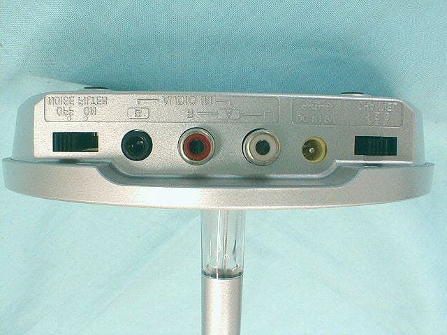
Click to zoom
Application Details
- Equipment Class
- DXX - Part 15 Low Power Communication Device Transmitter
- Date of Grant
- Nov 16, 2001
- Application Purpose
- Original Equipment
- Date of Application
- Nov 16, 2001
- Equipment Note
- RF Stereo Transmitter
- Frequency Range
- 913.50000000 - 914.50000000
- Company
- Sony Group Corporation
- Country
- Japan
Documents & Files
Document Text
Text extracted from the exhibit documents filed with the FCC. Open a document above to read the original.
Cover Letter(s)
A- PEX INTERNATIONAL CO., LTD. •HEAD OFFICE •4383-326 Asama-cho, Ise-shi, Mie-ken 516-0021 Japan TEL:0596-24-6717/FAX:0596-24-8020 Date: 16 November, 2001 Re: Sony Corporation FCC ID: AK8TMRR90 Dear Mr. Timothy Johnson, Please find the following replies to your comments (110701); 1) We uploaded it. Please find our revised test report (No.: 22CE0008-YW-1) in the filling. We corrected item 4.2 in the report. 2) We uploaded it. Please find the revised photos in the filing. 3) Regarding to Carrier level, we performed the testing by no modulation because there was not the difference between modulation and no modulation. Please find the carrier data in the filing. 4) We uploaded it. Please find the revised photos in the filing. 5) The carrier level always becomes stable between 85 to 115 % of input voltage. Al so, the frequency di dn’t change. Please find the data in the filing. Kanako Sanda A-Pex Int ernational Co., Ltd.
Cover Letter(s)
American Telecommunications Certification Body Inc. 6731 Whittier Ave, McLean, VA 22101 November 8, 2001 RE: Sony Corporation FCC ID: AK8TMRRF90 After a review of the submitted information, I have a few comments on the above referenced Application. 1) The test configuration photographs show that the audio cables were present during the test. Please update section 4.2 of the report to properly document this as well as to whether the input had any terminations. 2) Please provide a "close-up" photograph of the VCO portion of the transmitter (with the cover removed). It is not easy to distinguish components from the photograph already provided. 3) The EUT did not appear to have any external source for applying modulation to the unit during the test. Note that modulation may not be necessary if the unit was capable of supplying a normal transmitted carrier (reference ANSI C63.4, 13.1.1.1) without the input present. Please comment on whether or not the carrier level is affected by the fact that the modulation source was not present. 4) Please provide a clearer or higher resolution copy of the schematics. Portions of the schematic are difficult to read. 5) Please provide information regarding any change to the fundamental output radiated signal with respect to a variation of input voltage from 85% to 115% as specified by 15.31(e). Timothy R. Johnson Examining Engineer mailto: [email protected] The items indicated above must be submitted before processing can continue on the above referenced application. Failure to provide the requested information may result in application termination. Correspondence should be considered part of the permanent submission and may be viewed from the Internet after a Grant of Equipment Authorization is issued. Please do not respond to this correspondence using the email reply button. In order for your response to be processed expeditiously, you must submit your documents through the AmericanTCB.com website. Also, please note that partial responses increase processing time and should not be submitted. Any questions about the content of this correspondence should be directed to the sender.
External Photos
External Photos 1 Model: TMR-RF90 FCC ID: AK8TMRRF90 External Photos 2 Model: TMR-RF90 FCC ID: AK8TMRRF90
ID Label/Location Info
ID Label / Location Info. Model: TMR-RF90 FCC ID: AK8TMRRF90
Internal Photos
Internal Photos 1 Model: TMR-RF90 FCC ID: AK8TMRRF90 Antenna VCO Unit TX PWB (A side) VCO PWB DC IN terminal CHANNEL SW AUDIO IN terminals A B NOISE FLLTER SW Internal Photos 2 Model: TMR-RF90 FCC ID: AK8TMRRF90 TX PWB (B side)
Internal Photos
Internal Photos 3 Model: TMR-RF90 FCC ID: AK8TMRRF90 VCO PWB
Test Report
Test report No.: 22CE0008-YW-1 Page: 2 of 29 Issued date: November 5, 2001 Reviced date: November 16, 2001 FCC ID: AK8TMRRF90 A-pex International Co., Ltd. YOKOWA LAB. 108 Yokowa-cho, Ise-shi, Mie-ken 516-1106 JAPAN Telephone:int +81 596 39 1485 Facsimile: int +81 596 39 0232 CONTENTS PAGE SECTION 1: Client information 3 SECTION 2: Equipment under test (E.U.T.)3 SECTION 3: Test specification, methods & procedures5 SECTION 4: Operation of E.U.T. during testing6 SECTION 5: Summary of test results 8 SECTION 6: Conducted emission 9 SECTION 7: Radiated emission10 APPENDIX 1: Photographs of test setup11 APPENDIX 2:Test instruments11 APPENDIX 3: Data of EMI test11 Test report No.: 22CE0008-YW-1 Page: 3 of 29 Issued date: November 5, 2001 Reviced date: November 16, 2001 FCC ID: AK8TMRRF90 A-pex International Co., Ltd. YOKOWA LAB. 108 Yokowa-cho, Ise-shi, Mie-ken 516-1106 JAPAN Telephone:int +81 596 39 1485 Facsimile: int +81 596 39 0232 SECTION 1: Client information Company name: Sony Corporation Address: Sinagawa INTERCITY C Tower 2-15-3 konan Minato-ku, Tokyo, 108-6201, Japan Telephone Number: +81-3-5769-5640 Facsimile Number: +81-3-5769-5962 Contact Person: Kikuo Murata SECTION 2: Equipment under test (E.U.T.) 2.1Identification of E.U.T. Type of Equipment: Transmitter / AC Adaptor (Wireless Speaker System) Model No.: TMR-RF90 / AC-S901 ( SRS-RF90RK) FCC ID: AK8TMRRF90 Serial No.: 2 / 0027 Condition of EUT: Engineering prototype Rating: TMR-RF90 : DC IN 9.0V AC-S901 : Input:AC120V / 60Hz, 4W Output:DC9V, 100mA Country of Manufacture : Korea Receipt Date of Sample: October 12, 2001 Test report No.: 22CE0008-YW-1 Page: 4 of 29 Issued date: November 5, 2001 Reviced date: November 16, 2001 FCC ID: AK8TMRRF90 A-pex International Co., Ltd. YOKOWA LAB. 108 Yokowa-cho, Ise-shi, Mie-ken 516-1106 JAPAN Telephone:int +81 596 39 1485 Facsimile: int +81 596 39 0232 2.2Product Description Sony Corporation Model: TMR-RF90 / AC-S901 (referred to as the EUT in this report) is Transmitter / AC Adaptor of Wireless Speaker System. The specification is as follows; Carrier frequency:CH1:913.5MHz / CH2 :914.0MHz / CH3 :914.5MHz Modulation:FM Information on antenna:Integral Antenna Test report No.: 22CE0008-YW-1 Page: 5 of 29 Issued date: November 5, 2001 Reviced date: November 16, 2001 FCC ID: AK8TMRRF90 A-pex International Co., Ltd. YOKOWA LAB. 108 Yokowa-cho, Ise-shi, Mie-ken 516-1106 JAPAN Telephone:int +81 596 39 1485 Facsimile: int +81 596 39 0232 SECTION 3: Test specification, methods & procedures 3. 1Test Specification Test Specification: FCC Part 15 Subpart C Section 15.207 and Section 15.249 Title: FCC 47CFR Part15 Radio Frequency Device Subpart C Intentional Radiators 15.207 Conducted emission limits; general requirements 15.249 Operation in the band 902-928MHz, 2400-2483.5MHz, 5725-5875MHz and 24.0-24.25GHz 3.2Methods & Procedures No.ItemTest ProcedureSpecificationRemarks 1Conducted emissionANSI C63.4:1992 15.207(a) - 2Radiated emissionANSI C63.4:1992 15.249 3m 3.3 Additions or deviations to standards No addition, deviation or exclusion has been made from standards. Test report No.: 22CE0008-YW-1 Page: 6 of 29 Issued date: November 5, 2001 Reviced date: November 16, 2001 FCC ID: AK8TMRRF90 A-pex International Co., Ltd. YOKOWA LAB. 108 Yokowa-cho, Ise-shi, Mie-ken 516-1106 JAPAN Telephone:int +81 596 39 1485 Facsimile: int +81 596 39 0232 SECTION 4: Operation of E.U.T. during testing 4.1Operating Modes The EUT exercise program used during radiated and conducted testing was designed to exercise the various system components in a manner similar to typical use. The operating mode/system were as follows: Operation: Transmitting CH1: 913.5MHz CH2: 914.0MHz CH3: 914.5MHz Justification: The system was configured in typical fashion (as a customer would normally use it) for testing. 4.2 Configuration and peripherals Front View OpenAB Top View Open A B *Cabling was taken into consideration and test data was taken under worse case conditions. Test report No.: 22CE0008-YW-1 Page: 7 of 29 Issued date: November 5, 2001 Reviced date: November 16, 2001 FCC ID: AK8TMRRF90 A-pex International Co., Ltd. YOKOWA LAB. 108 Yokowa-cho, Ise-shi, Mie-ken 516-1106 JAPAN Telephone:int +81 596 39 1485 Facsimile: int +81 596 39 0232 Description of EUT and Support equipment No.ItemModel numberSerial numberManufacturerFCC ID ATransmitterTMR-RF902Sony CorporationAK8TMRRF90 (EUT) BAC AdaptorAC-S9010027Sony CorporationAK8TMRRF90 (EUT) List of cables used No.NameLength (m)ShieldBackshell MaterialRemark DC Power Cable2.1N Polyvinyl chloride AV Cable1.5Y Polyvinyl chloride - Test report No.: 22CE0008-YW-1 Page: 8 of 29 Issued date: November 5, 2001 Reviced date: November 16, 2001 FCC ID: AK8TMRRF90 A-pex International Co., Ltd. YOKOWA LAB. 108 Yokowa-cho, Ise-shi, Mie-ken 516-1106 JAPAN Telephone:int +81 596 39 1485 Facsimile: int +81 596 39 0232 SECTION 5: Summary of test results 5.1Test results No.ItemTest ProcedureSpecification Worst marginResult 1Conducted emissionANSI C63.4:1992 15.207(a) 12.9dB (0.4500MHz: L1) : CH1Complied 2Radiated emissionANSI C63.4:1992 15.249 Fundamental 7.4dB (913.5MHz: Vertical) : CH1 7.4dB (914.0MHz: Vertical) : CH2 7.2dB (914.5MHz: Vertical) : CH3 Spurious 3.4dB (2.7404GHz: Vertical) : CH1 2.7dB (2.7419GHz: Vertical) : CH2 4.1dB (2.7434GHz: Vertical) : CH3 Complied A-PEX INTERNATIONAL hereby confirms that E.U.T., in the configuration tested, complies with the specifications FCC Part 15 Subpart C. <–20dB Bandwidth> Refer to Appendix 3. 5.2Uncertainty Conducted Emission Test The measurement uncertainty (with a 95% confidence level) for this test was ±2.0dB. The data listed in this test report may exceed the test limit because it does not have enough margin. The data listed in this test report has enough margin, more than site margin. Radiated Emission Test The measurement uncertainty (with a 95% confidence level) for this test using Biconical antenna is ±4.4dB. The measurement uncertainty (with a 95% confidence le…
Text truncated - open the document above for the full version.
Test Setup Photos
Test report No.: 22CE0008-YW-1 Page: 12 of 29 Issued date: November 5, 2001 FCC ID: AK8TMRRF90 A-pex International Co., Ltd. YOKOWA LAB. 108 Yokowa-cho, Ise-shi, Mie-ken 516-1106 JAPAN Telephone:int +81 596 39 1485 Facsimile: int +81 596 39 0232 Conducted emission Test report No.: 22CE0008-YW-1 Page: 13 of 29 Issued date: November 5, 2001 FCC ID: AK8TMRRF90 A-pex International Co., Ltd. YOKOWA LAB. 108 Yokowa-cho, Ise-shi, Mie-ken 516-1106 JAPAN Telephone:int +81 596 39 1485 Facsimile: int +81 596 39 0232 Radiated emission
Contact Information
Applicant
Kazuyuki Hori(Chief EMC/RF Compliance Specialist)
Technical Contact
A-Pex International Co., Ltd.Naoki Sakamoto
[email protected]+81-596-39-1485
108 Yokowa-cho · Ise-shi, Mie-ken · Japan
Non-Technical Contact
A-Pex International Co., Ltd.Motomu Kawano
[email protected]+81-596-24-6717
Test Firm
UL Japan, Inc.Kazunori Nishimura
Technical Specifications
| # | Rule Parts | Frequency Range | Power Output |
|---|---|---|---|
| 1 | 15C | 913.5 MHz - 914.5 MHz | - |
Other Applications from Sony Group Corporation
AK8WW81782
Aug 21, 2026Radio Equipment
Equipment Class
DSS - Part 15 Spread Spectrum TransmitterAK8CFIZCP2
Aug 03, 2026Wireless Controller
Equipment Class
DSS - Part 15 Spread Spectrum TransmitterAK8OEV321MUH
Apr 14, 2026LCD Monitor
Equipment Class
JAD - Part 15 Class A Digital DeviceAK8OEV431MUH
Apr 14, 2026LCD Monitor
Equipment Class
JAD - Part 15 Class A Digital DeviceAK8OEV271MUH
Apr 14, 2026LCD Monitor
Equipment Class
JAD - Part 15 Class A Digital Device