AK8TMRRF960RRF Stereo Transmitter
Sony Group Corporation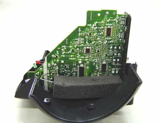
Click to zoom
Application Details
- Equipment Class
- DXX - Part 15 Low Power Communication Device Transmitter
- Date of Grant
- Nov 16, 2003
- Application Purpose
- Original Equipment
- Date of Application
- Nov 16, 2003
- Equipment Note
- RF Stereo Transmitter
- Frequency Range
- 913.50000000 - 914.50000000
- Company
- Sony Group Corporation
- Country
- Japan
Documents & Files
Document Text
Text extracted from the exhibit documents filed with the FCC. Open a document above to read the original.
Users Manual
MDR-RF920RK/RF960RK_U [US,FR,ES]3-264-043-11(1) Operating Instructions Mode d’emploi Manual de instrucciones Wireless Stereo Headphone System 3-264-043-11(1) © 2004 Sony Corporation MDR-RF920RK MDR-RF960RK FR ES GB MDR-RF920RK/RF960RK_U [US,FR,ES]3-264-043-11(1) 3 GB Welcome! Thank you for purchasing the Sony MDR-RF920RK/RF960RK Wireless Stereo Headphone System. Before operating the unit, please read this manual thoroughly and retain it for future reference. Some features are: •Wireless system that allows you to listen to a program free from the restriction of a cord •High fidelity sound reproduction •A compact transmitter with an AC power adaptor (supplied) enables simple charging of the headphone batteries. Just by placing the headphones on the transmitter, headphone batteries can be charged. •Comfortable Circum-aural headphones with self adjusting head band •Automatic ON/OFF function on headphones to preserve battery power •As a power saving feature, the transmitter automatically turns ON when the audio signal is detected and OFF when the signal is not received. Notes on receiving performance The system for this equipment utilizes very high frequency signals in the 900 MHz band so the receiving performance may deteriorate due to the surroundings. The following examples illustrate conditions that may reduce the possible receiving range or cause interference with reception. •Inside a building with walls containing steel beams. •Area with many steel file cabinets, etc. •Area with many electrical appliances capable of generating electromagnetic noise. •Transmitter is placed on a metal instrument. •Area facing roadways. •Noise or interfering signals exist in the surroundings due to radio transceivers in trucks, etc. •Noise or interfering signals exist in the surroundings due to wireless communication systems installed along roadways. Table of contents Getting started Unpacking ................................................. 4 Charging the supplied rechargeable batteries ............................................... 4 Setting up the transmitter ........................ 7 Operating the system Listening to a program ............................. 9 The effective areas of the transmitter .. 11 Replacing the ear pads ........................... 11 Additional information Precautions .............................................. 12 Troubleshooting ...................................... 12 Specifications ........................................... 13 GB 4 GB MDR-RF920RK/RF960RK_U [US,FR,ES]3-264-043-11(1) N Getting started Unpacking Check that you have the following items: • The headphones (1) • The transmitter (1) •AC power adaptor (1) •Unimatch plug adaptor (1) (stereo mini jack y stereo phone plug) • Connecting cord (1) (phono plugs y stereo mini plug), 1 m (3.3 ft.) • Rechargeable nickel-metal hydride batteries (2) Charging the supplied rechargeable batteries The supplied rechargeable nickel-metal hydride batteries are not charged from the first time you use them. Be sure to charge them before use. To charge the headphones, place them on the transmitter. 1Press the button of the left housing to open the battery compartment lid. The battery compartment lid comes off. 2Insert the supplied rechargeable nickel-metal hydride batteries into the battery compartment matching the 3 terminals on the batteries to the 3 marks in the compartment. Do not use rechargeable batteries other than the supplied ones. Button MDR-RF920RK/RF960RK_U [US,FR,ES]3-264-043-11(1) 5 GB continue to next page 3Close the battery compartment lid. 4Connect the supplied AC power adaptor to the transmitter. 5Rest the headphones on the transmitter so that the headphones’ contact point meets the transmitter’s contact pin while making sure that the charging indicator lights in green. Charging is completed in about 16 hours and the charging indicator goes off. When placing the headphones on the transmitter, be sure to hold them level with both hands and that the right and left housings are placed straight down on the transmitter, and then tilt them back as illustrated above. AC power adaptor (supplied) to DC IN 9V jack to an AC outlet Transmitter When the indicator does not light in green Check if the right and left headphones are rested on the transmitter correctly. The indicator will not light up if the headphones’ contact point does not meet the transmitter’s contact pin. Remove the headphones and replace them on the transmitter again so that the indicator lights in green. To recharge the headphone battery after use Place the headphones on the transmitter after use. Since the built-in timer recognizes when charging is complete, there is no need to remove the headphones from the transmitter after charging. Notes •The transmitter automatically turns off while charging the batteries. •This system is designed to charge only the supplied rechargeable batteries type BP-HP550 for safety. Note that other types of rechargeable batteries cannot be charged with this system. •If dry batteries are installed, they cannot be charged. •Do not attempt to use the supplied BP-HP550 rechargeable batteries for other components. They are for use with this system only. •Charge in an environmental temperature of between 0 ̊C and 40 ̊C (between 32 ̊F and 104 ̊F). Left housing Right housing 6 GB MDR-RF920RK/RF960RK_U [US,FR,ES]3-264-043-11(1) Charging and usage hours * 1 at 1kHz, 1mW+1mW output * 2 hours required to fully charge empty batteries * 3 Time stated above may vary, depending on the temperature or conditions of use. Using the headphones with dry batteries (sold separately) Commercially available (size AAA) dry batteries can also be used to power the headphones. Install the batteries in the same manner as described in steps 1 through 3 of “Charging the supplied rechargeable batteries.” When dry batteries are installed, the battery charge function is not activated. Battery life (Using Sony alkaline battery LR03/AM-4(N)) * 1 at 1kHz, 1mW+1mW outp…
Text truncated - open the document above for the full version.
External Photos
External Photo 1 To p Front RF Stereo Transmitter: TMR-RF960R Charge contact pin Power/CHG Indicator External Photo 2 Side RF Stereo Transmitter: TMR-RF960R External Photo 3 Rear Bottom RF Stereo Transmitter: TMR-RF960R CHANNEL SW NOISE FILETER SW AUDIO IN terminals B(L,R) A DC IN terminal External Photo 4 Nameplate (including FCC ID, IC Certification No.) & FCC Label RF Stereo Transmitter: TMR-RF960R THIS DEVICE COMPLIES WITH PART15 OF THE FCC RULES. OPERATION IS SUBJECT TO THE FOLLOWING TWO CONDITIONS: (1) THIS DEVICE MAY NOT CAUSE HARMFUL INTERFERENCE. AND (2) THIS DEVICE MUST ACCEPT ANY INTERFERENCE RECEIVED, INCLUDING INTERFERENCE THAT MAY CAUSE UNDESIRED OPERATION . Nameplate (Molding) FCC Label
ID Label/Location Info
External Photo 4 Nameplate (including FCC ID, IC Certification No.) & FCC Label RF Stereo Transmitter: TMR-RF960R THIS DEVICE COMPLIES WITH PART15 OF THE FCC RULES. OPERATION IS SUBJECT TO THE FOLLOWING TWO CONDITIONS: (1) THIS DEVICE MAY NOT CAUSE HARMFUL INTERFERENCE. AND (2) THIS DEVICE MUST ACCEPT ANY INTERFERENCE RECEIVED, INCLUDING INTERFERENCE THAT MAY CAUSE UNDESIRED OPERATION . Nameplate (Molding) FCC Label
Internal Photos
Internal Photo 1 RF Stereo Transmitter: TMR-RF960R VCO Unit Antenna TX-BASE PWB (A side) Internal Photo 2 RF Stereo Transmitter: TMR-RF960R VCO PWB TX-BASE PWB (B side) TX-BASE PWB (A side) Antenna AUDIO IN terminals B A DC IN terminal CHANEL SW NOISE FILTER SW Internal Photo 3 RF Stereo Transmitter: TMR-RF960R TX-BASE PWB (B side) Antenna
Test Report
Test report No. : 24BE0092-HO-1 Page : 10 of 27 Issued date : November 7, 2003 FCC ID : AK8TMRRF960R UL Apex Co., Ltd. Head Office EMC Lab. 4383-326 Asama-cho, Ise-shi, Mie-ken 516-0021 JAPAN Telephone : +81 596 24 8116 Facsimile : +81 596 24 8124 MF060b(10.04.03) APPENDIX 1: Photographs of test setup Conducted Emission Front Side Test report No. : 24BE0092-HO-1 Page : 11 of 27 Issued date : November 7, 2003 FCC ID : AK8TMRRF960R UL Apex Co., Ltd. Head Office EMC Lab. 4383-326 Asama-cho, Ise-shi, Mie-ken 516-0021 JAPAN Telephone : +81 596 24 8116 Facsimile : +81 596 24 8124 MF060b(10.04.03) Radiated Emission Front Side
Test Setup Photos
Test report No. : 24BE0092-HO-1 Page : 10 of 27 Issued date : November 7, 2003 FCC ID : AK8TMRRF960R UL Apex Co., Ltd. Head Office EMC Lab. 4383-326 Asama-cho, Ise-shi, Mie-ken 516-0021 JAPAN Telephone : +81 596 24 8116 Facsimile : +81 596 24 8124 MF060b(10.04.03) APPENDIX 1: Photographs of test setup Conducted Emission Front Side Test report No. : 24BE0092-HO-1 Page : 11 of 27 Issued date : November 7, 2003 FCC ID : AK8TMRRF960R UL Apex Co., Ltd. Head Office EMC Lab. 4383-326 Asama-cho, Ise-shi, Mie-ken 516-0021 JAPAN Telephone : +81 596 24 8116 Facsimile : +81 596 24 8124 MF060b(10.04.03) Radiated Emission Front Side
Contact Information
Applicant
Kazuyuki Hori(Chief EMC/RF Compliance Specialist)
Technical Contact
Non-Technical Contact
UL Apex Co., Ltd.Keijiro Kumagai
[email protected]81-596-24-8116
Test Firm
UL Apex Co., Ltd.Toshihiro Ikegami
Technical Specifications
| # | Rule Parts | Frequency Range | Power Output |
|---|---|---|---|
| 1 | 15C | 913.5 MHz - 914.5 MHz | - |
Other Applications from Sony Group Corporation
AK8WW81782
Aug 21, 2026Radio Equipment
Equipment Class
DSS - Part 15 Spread Spectrum TransmitterAK8CFIZCP2
Aug 03, 2026Wireless Controller
Equipment Class
DSS - Part 15 Spread Spectrum TransmitterAK8OEV321MUH
Apr 14, 2026LCD Monitor
Equipment Class
JAD - Part 15 Class A Digital DeviceAK8OEV431MUH
Apr 14, 2026LCD Monitor
Equipment Class
JAD - Part 15 Class A Digital DeviceAK8OEV271MUH
Apr 14, 2026LCD Monitor
Equipment Class
JAD - Part 15 Class A Digital Device