AK8TMRRF970RRF Stereo Transmitter
Sony Group Corporation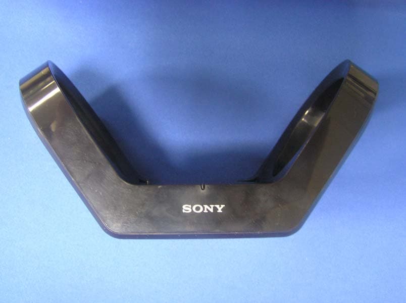
Click to zoom
Application Details
- Equipment Class
- DXX - Part 15 Low Power Communication Device Transmitter
- Date of Grant
- Mar 14, 2007
- Application Purpose
- Original Equipment
- Date of Application
- Mar 14, 2007
- Equipment Note
- RF Stereo Transmitter
- Frequency Range
- 915.50000000 - 916.50000000
- Company
- Sony Group Corporation
- Country
- Japan
Documents & Files
Document Text
Text extracted from the exhibit documents filed with the FCC. Open a document above to read the original.
Users Manual
MDR-RF925RK,MDR-RF970RK_U [US,FR] 3-100-340-11(1) 5Rest the headphones on the transmitter so that the transmitter’s POWER/CHG indicator lights in red. Please place the headphones on the transmitter so that the triangle arrow would be matched. If the headphones are not properly placed, it will not be charged. Charging will take about 16 hours, after which the POWER/CHG indicator will go off. About the charging method of the system This system employs a contactless charge method that requires no terminals by the electromagnetic induction. Notes •Do not leave any metallic objects (coin, clip, etc.) near the transmitter’s charging point. The transmitter and the metal might become hot and it is dangerous. •Do not leave any objects susceptible to magnetism (cash cards, floppy disks with magnetic coding, etc.) near the system. Exposure to the transmitter’s electromagnetic field may render them unusable. •Do not place a radio near the system. A noise may be heard from the radio. In such a case, change the angle of the radio or move away from the system so that a noise is not heard. When the transmitter’s POWER/CHG indicator does not light up red Check if the right and left headphones are rested on the transmitter correctly. Remove the headphones and replace them on the transmitter again so that the POWER/CHG indicator lights in red. To recharge the headphone battery after use Place the headphones on the transmitter after use. Since the built-in timer recognizes when charging is complete, there is no need to remove the headphones from the transmitter after charging. Notes •The transmitter automatically stops sending RF signals while charging the battery. •This system is designed to charge only the supplied rechargeable battery type BP-HP550-11 for safety. Note that other types of rechargeable batteries cannot be charged with this system. •If dry batteries are installed, they cannot be charged. •Do not attempt to use the supplied BP-HP550-11 rechargeable battery for other components. They are for use with this system only. •Charge in an environmental temperature of between 0 °C and 40 °C (between 32 °F and 104 °F). Charging and usage hours Approx. chargingApprox. usage time* 1 hours* 1 1 hour60 minutes* 3 40 minutes* 3 16 hours* 2 18 hours* 3 14 hours* 3 * 1 at 1 kHz, 1 mW+1 mW output * 2 hours required to fully charge an empty battery * 3 Time stated above may vary, depending on the temperature or conditions of use. Using the headphones with dry batteries (sold separately) Commercially available (size AAA) dry batteries can also be used to power the headphones. Install the batteries in the same manner as described in steps 1 through 3 of “Charging the supplied rechargeable battery.” When dry batteries are installed, the battery charge function will not be activated. Battery life (Using Sony alkaline batteries LR03/AM-4 (N)) ModelApprox. hours* 1 MDR-RF925RK28 hours* 2 MDR-RF970RK22 hours* 2 * 1 at 1 kHz, 1 mW+1 mW output * 2 Time stated above may vary, depending on the temperature or conditions of use. LR Transmitter Headphones POWER/CHG indicator Wireless Stereo Headphone System © 2007 Sony Corporation Printed in China Operating Instructions Mode d’emploi 3-100-340-11(1) English WARNING To reduce the risk of fire or electric shock, do not expose this apparatus to rain or moisture. To reduce the risk of fire or electric shock, do not place objects filled with liquids, such as vases, on the apparatus. To avoid electrical shock, do not open the cabinet. Refer servicing to qualified personnel only. Connect AC power adaptor to an easily accessible AC outlet. Should you notice an abnormality in AC power adaptor, disconnect it from the AC outlet immediately. Do not install the appliance in a confined space, such as a bookcase or built-in cabinet. Do not expose the battery to excessive heat such as direct sunlight, fire or the like. Information You are cautioned that any changes or modifications not expressly approved in this manual could void your authority to operate this equipment. If you have any questions about this product, you may call: Sony Customer Information Services Center 1-800-222-7669 or http://www.sony.com/ Declaration of Conformity Trade Name:SONY Model No.:MDR-RF925R MDR-RF970R (Headphones Unit) Responsible Party:Sony Electronics Inc. Address:16530 Via Esprillo, San Diego, CA 92127 USA Telephone No.:858-942-2230 This device complies with Part 15 of the FCC Rules. Operation is subject to the following two conditions: (1) this device may not cause harmful interference, and (2) this device must accept any interference received, including interference that may cause undesired operation. Note This equipment has been tested and found to comply with the limits for a Class B digital device, pursuant to Part 15 of the FCC Rules. These limits are designed to provide reasonable protection against harmful interference in a residential installation. This equipment generates, uses and can radiate radio frequency energy and, if not installed and used in accordance with the instructions, may cause harmful interference to radio communications. However, there is no guarantee that interference will not occur in a particular installation. If this equipment does cause harmful interference to radio or television reception, which can be determined by turning the equipment off and on, the user is encouraged to try to correct the interference by one or more of the following measures: –Reorient or relocate the receiving antenna. –Increase the separation between the equipment and receiver. –Connect the equipment into an outlet on a circuit different from that to which the receiver is connected. –Consult the dealer or an experienced radio/ TV technician for help. For the customers in the Canada Operation is subject to the following two conditions: (1) this device may not cause interference, and (2) this device must accept any interference, including interference that may cause undesired operation of the device. F…
Text truncated - open the document above for the full version.
External Photos
External Photo Sony Corporation RF Stereo Transmitter[Model: TMR-RF970R] FCC ID: AK8TMRRF970R/ IC Number: 409B-TMRRF970 Front Rear External Photo Sony Corporation RF Stereo Transmitter[Model: TMR-RF970R] FCC ID: AK8TMRRF970R/ IC Number: 409B-TMRRF970 Top Bottom External Photo Sony Corporation RF Stereo Transmitter[Model: TMR-RF970R] FCC ID: AK8TMRRF970R/ IC Number: 409B-TMRRF970 Right Left
ID Label/Location Info
TMR-RF970R Nameplate Photos Nameplate Nameplate
Internal Photos
Internal Photo Sony Corporation RF Stereo Transmitter [Model: TMR-RF970R] FCC ID: AK8TMRRF970R /IC Number: 409B-TMRRF970 Overall View Front Internal Photo Sony Corporation RF Stereo Transmitter [Model: TMR-RF970R] FCC ID: AK8TMRRF970R /IC Number: 409B-TMRRF970 Rear Front without cover
Test Report
Test report No. : 27EE0160-HO-F-1 Page : 2 of 23 Issued date : January 30, 2007 Revised date : March 5, 2007 FCC ID : AK8TMRRF970R UL Apex Co., Ltd. Head Office EMC Lab. 4383-326 Asama-cho, Ise-shi, Mie-ken 516-0021 JAPAN Telephone : +81 596 24 8116 Facsimile : +81 596 24 8124 MF060b(01.06.05) CONTENTS PAGE SECTION 1: Client information ............................................................................................................ 3 SECTION 2: Equipment under test (E.U.T.)........................................................................................ 3 SECTION 3: Test specification, procedures & results......................................................................... 4 SECTION 4: Operation of E.U.T. during testing .................................................................................6 SECTION 5: Conducted Emission......................................................................................................... 7 SECTION 6: Radiated emission (Fundamental and Spurious Emission) .......................................... 8 APPENDIX 1: Photographs of test setup .............................................................................................. 9 Conducted Emission ...................................................................................................................... 9 Radiated Emission........................................................................................................................ 10 APPENDIX 2: Data of EMI test............................................................................................................ 11 Conducted Emission .................................................................................................................... 11 Radiated Emission (Fundamental and Spurious emission)below 1GHz ................................. 15 –20dB Bandwidth ......................................................................................................................... 21 99% Occupied Bandwidth........................................................................................................... 22 APPENDIX 3:Test instruments ............................................................................................................ 23 Test report No. : 27EE0160-HO-F-1 Page : 3 of 23 Issued date : January 30, 2007 Revised date : March 5, 2007 FCC ID : AK8TMRRF970R UL Apex Co., Ltd. Head Office EMC Lab. 4383-326 Asama-cho, Ise-shi, Mie-ken 516-0021 JAPAN Telephone : +81 596 24 8116 Facsimile : +81 596 24 8124 MF060b(01.06.05) SECTION 1: Client information Company Name : Sony Corporation Address : Shinagawa INTERCITY C Tower, 2-15-3 Konan, Minato-ku, Tokyo 108-6201, Japan Telephone Number : +81-3-5769-5640 Facsimile Number : +81-3-5769-5085 Contact Person : Kikuo Murata <Remarks for data sheets> *Sony EMCS Corporation Saitama TEC (Subsidiary Company Name) is on behalf of the applicant: Sony Corporation. SECTION 2: Equipment under test (E.U.T.) 2.1 Identification of E.U.T. Type of Equipment : RF Stereo Transmitter Model No. : TMR-RF970R Serial No. : 14# Rating : DC 12V(use AC adaptor AC-S1202S/input AC120V 60Hz , output DC12V) Country of Manufacture : China Receipt Date of Sample : December 14, 2006 Condition of EUT : Engineering prototype (Not for Sale: This sample is equivalent to mass-produced items.) 2.2 Product Description Model No: TMR-RF970R is RF Stereo Transmitter. Clock frequency Pilot Tone :38kHz,19kHz PLL :4MHz Charge :125kHz Micro computer :1MHz Equipment Type Transmitter Frequency of Operation 915.5 MHz to 916.5 MHz Channel spacing 500kHz Type of Modulation FM Antenna Type Integral Antenna Method of frequency generation Synthesizer Power Supply (Inner) DC 5.0V Test report No. : 27EE0160-HO-F-1 Page : 4 of 23 Issued date : January 30, 2007 Revised date : March 5, 2007 FCC ID : AK8TMRRF970R UL Apex Co., Ltd. Head Office EMC Lab. 4383-326 Asama-cho, Ise-shi, Mie-ken 516-0021 JAPAN Telephone : +81 596 24 8116 Facsimile : +81 596 24 8124 MF060b(01.06.05) SECTION 3: Test specification, procedures & results 3.1 Test Specification Test Specification : FCC Part15 Subpart C : 2006 Title : FCC 47CFR Part15 Radio Frequency Device Subpart C Intentional Radiators Section 15.249 Operation within the bands 902 – 928MHz, 2400 – 2483.5MHz, 5725 – 5875MHz, and 24.0 – 24.25GHz FCC 15.31 (e) This EUT provides stable voltage (DC 5.0V) constantly to RF Module regardless of input voltage. Therefore, this EUT complies with the requirement. FCC Part 15.203 Antenna requirement It is impossible for end users to replace the antenna, because the antenna is mounted inside of the EUT. Therefore, the equipment complies with the antenna requirement of Section 15.203. 3.2 Procedures and results No. Item Test Procedure Specification Remarks Deviation Worst margin Result 1 Conducted Emission FCC: ANSI C63.4:2003 7. AC powerline conducted emission measurements FCC: Section 15.207 - N/A 46.3dB 0.27386MHz N, AV Complied 2 Electric Field Strength of Fundamental Emission FCC: ANSI C63.4:2003 13. Measurement of intentional radiators FCC Section 15.249 Radiated N/A 1.8dB 916.512MHz, Horizontal, QP Complied 3 Electric Field Strength of Spurious Emission FCC: ANSI C63.4:2003 13. Measurement of intentional radiators FCC Section 15.249, Section 15.209 *1) Radiated N/A 4.9 dB 905.801MHz, Vertical, QP Complied 4 -20dB bandwidth FCC: ANSI C63.4:2003 13. Measurement of intentional radiators FCC Section 15.215 Radiated N/A - Complied Note: UL Apex’s EMI Work procedures No. QPM05 and QPM15. *1) The limit for above 1GHz was applied with Section 15.209 which is more stringent. *These tests were performed without any deviations from test procedure except for additions or exclusions. 3.3 Addition to standards No. Item Test Procedure Specification Remarks Deviation Worst margin Results 1 99% Occupied Band Width RSS-Gen 4.4.1 - Radiated N/A N/A N/A Test report No. : 27EE0160-HO-F-1 Page : 5 of 23 Issued date : January…
Text truncated - open the document above for the full version.
Test Report
Test report No. : 27EE0160-HO-F-1 Page : 11 of 23 Issued date : January 30, 2007 Revised date : March 5, 2007 FCC ID : AK8TMRRF970R UL Apex Co., Ltd. Head Office EMC Lab. 4383-326 Asama-cho, Ise-shi, Mie-ken 516-0021 JAPAN Telephone : +81 596 24 8116 Facsimile : +81 596 24 8124 MF060b(01.06.05) APPENDIX 2: Data of EMI test Conducted Emission DATA OF CONDUCTED EMISSION TEST UL Apex Co., Ltd. Head Office EMC Lab. No.4 Semi Anechoic Chamber Date : 2007/01/19 Applicant : Sony EMCS Corporation Saitama TECReport No.:27EE0160-HO Kind of EUT : RF Stereo TransmitterPower:AC120V / 60Hz Model No.: TMR-RF970R Temp°C/Humi%:24deg.C / 30% Serial No. : 14# Operator:Takumi Shimada Mode / Remarks : Transmitting ch_1 LIMIT : FCC15.207 QP FCC15.207 AV CHART:WITH FACTOR,Peak hold data.Data is uncorrected. CALCURATION:RESULT=READING+C.F(LISN LOSS+CABLE LOSS) Except for the above table : adequate margin data below the limits. Frequency[Hz] [dBuV]<< PEAK DATA >>N:PEAK .15M 30M .2M.3M .5M .7M1M2M3M5M7M10M20M 0 10 20 30 40 50 60 70 80 Frequency[Hz] [dBuV]<< PEAK DATA >>L:PEAK .15M 30M .2M.3M .5M .7M1M2M3M5M7M10M20M 0 10 20 30 40 50 60 70 80 Test report No. : 27EE0160-HO-F-1 Page : 12 of 23 Issued date : January 30, 2007 Revised date : March 5, 2007 FCC ID : AK8TMRRF970R UL Apex Co., Ltd. Head Office EMC Lab. 4383-326 Asama-cho, Ise-shi, Mie-ken 516-0021 JAPAN Telephone : +81 596 24 8116 Facsimile : +81 596 24 8124 MF060b(01.06.05) Conducted Emission DATA OF CONDUCTED EMISSION TEST UL Apex Co., Ltd. Head Office EMC Lab. No.4 Semi Anechoic Chamber Date : 2007/01/19 Applicant : Sony EMCS Corporation Saitama TECReport No.:27EE0160-HO Kind of EUT : RF Stereo TransmitterPower:AC120V / 60Hz Model No.: TMR-RF970R Temp°C/Humi%:24deg.C / 30% Serial No.: 14# Operator:Takumi Shimada Mode / Remarks : Transmitting ch_2 LIMIT : FCC15.207 QP FCC15.207 AV CHART:WITH FACTOR,Peak hold data.Data is uncorrected. CALCURATION:RESULT=READING+C.F(LISN LOSS+CABLE LOSS) Except for the above table : adequate margin data below the limits. Frequency[Hz] [dBuV]<< PEAK DATA >> N:PEAK .15M 30M .2M.3M .5M .7M1M2M3M5M7M10M20M 0 10 20 30 40 50 60 70 80 Frequency[Hz] [dBuV]<< PEAK DATA >> L:PEAK .15M 30M .2M.3M .5M .7M1M2M3M5M7M10M20M 0 10 20 30 40 50 60 70 80 Test report No. : 27EE0160-HO-F-1 Page : 13 of 23 Issued date : January 30, 2007 Revised date : March 5, 2007 FCC ID : AK8TMRRF970R UL Apex Co., Ltd. Head Office EMC Lab. 4383-326 Asama-cho, Ise-shi, Mie-ken 516-0021 JAPAN Telephone : +81 596 24 8116 Facsimile : +81 596 24 8124 MF060b(01.06.05) Conducted Emission DATA OF CONDUCTED EMISSION TEST UL Apex Co., Ltd. Head Office EMC Lab. No.4 Semi Anechoic Chamber Date : 2007/01/20 Applicant : Sony EMCS Corporation Saitama TECReport No.:27EE0160-HO Kind of EUT : RF Stereo TransmitterPower:AC120V / 60Hz Model No.: TMR-RF970R Temp°C/Humi%:24deg.C / 30% Serial No.: 14# Operator:Takumi Shimada Mode / Remarks : Transmitting ch_3 LIMIT : FCC15.207 QP FCC15.207 AV CHART:WITH FACTOR,Peak hold data.Data is uncorrected. CALCURATION:RESULT=READING+C.F(LISN LOSS+CABLE LOSS) Except for the above table : adequate margin data below the limits. Frequency[Hz] [dBuV]<< PEAK DATA >> N:PEAK .15M 30M .2M.3M .5M .7M1M2M3M5M7M10M20M 0 10 20 30 40 50 60 70 80 Frequency[Hz] [dBuV]<< PEAK DATA >> L:PEAK .15M 30M .2M.3M .5M .7M1M2M3M5M7M10M20M 0 10 20 30 40 50 60 70 80 Test report No. : 27EE0160-HO-F-1 Page : 14 of 23 Issued date : January 30, 2007 Revised date : March 5, 2007 FCC ID : AK8TMRRF970R UL Apex Co., Ltd. Head Office EMC Lab. 4383-326 Asama-cho, Ise-shi, Mie-ken 516-0021 JAPAN Telephone : +81 596 24 8116 Facsimile : +81 596 24 8124 MF060b(01.06.05) Conducted Emission DATA OF CONDUCTED EMISSION TEST UL Apex Co., Ltd. Head Office EMC Lab. No.4 Semi Anechoic Chamber Date : 2007/01/20 Applicant : Sony EMCS Corporation Saitama TECReport No.:27EE0160-HO Kind of EUT: RF Stereo TransmitterPower:AC120V / 60Hz Model No. : TMR-RF970R Temp°C/Humi%:24deg.C / 30% Serial No.: 14# Operator:Takumi Shimada Mode / Remarks : Transmitting ch_3 LIMIT : FCC15.207 QP FCC15.207 AV CHART:WITH FACTOR,Peak hold data.Data is uncorrected. CALCURATION:RESULT=READING+C.F(LISN LOSS+CABLE LOSS) Except for the above table : adequate margin data below the limits. Frequency[Hz] [dBuV] << QP/AV DATA >> L :QP :AV N :QP :AV .15M 30M .2M .3M .5M .7M 1M2M3M5M7M10M20M 0 10 20 30 40 50 60 70 80 _ Frequency _ Reading Level _ Reading Level _ Corr . _ Results _ Results _ Limit _ Limit _ Margin _ Margin _ Phase _ Frequency _ QP _ AV _ Factor _ QP _ AV _ QP _ AV _ QP _ AV _ Phase _ [ MHz ] _ [ dBuV ] _ [ dBuV ] _ [ dB ] _ [dBuV] _ [dBuV] _ [dBuV] _ [dBuV] _ [dB] _ [dB] _ Phase _ 0 . 27386 _ 4 . 9 _ 4 . 6 _ 0 . 1 _ 5.0 _ 4.7 _ 61.0 _ 51.0 _ 56.0 _ 46.3 _ N _ 0 . 68197 _ - 2 . 5 _ - 5 . 1 _ 0 . 3 _ -2.2 _ -4.8 _ 56.0 _ 46.0 _ 58.2 _ 50.8 _ N _ 0 . 81895 _ - 1 . 1 _ - 2 . 8 _ 0 . 3 _ -0.8 _ -2.5 _ 56.0 _ 46.0 _ 56.8 _ 48.5 _ N _ 0 . 95520 _ - 0 . 4 _ - 1 . 9 _ 0 . 3 _ -0.1 _ -1.6 _ 56.0 _ 46.0 _ 56.1 _ 47.6 _ N _ 1 . 22832 _ - 2 . 2 _ - 4 . 7 _ 0 . 3 _ -1.9 _ -4.4 _ 56.0 _ 46.0 _ 57.9 _ 50.4 _ N _ 1 . 36469 _ - 2 . 5 _ - 4 . 9 _ 0 . 3 _ -2.2 _ -4.6 _ 56.0 _ 46.0 _ 58.2 _ 50.6 _ N _ 0 . 27386 _ 0 . 9 _ - 0 . 3 _ 0 . 1 _ 1.0 _ -0.2 _ 61.0 _ 51.0 _ 60.0 _ 51.2 _ L _ 0 . 68197 _ - 4 . 3 _ - 7 . 6 _ 0 . 3 _ -4.0 _ -7.3 _ 56.0 _ 46.0 _ 60.0 _ 53.3 _ L _ 0 . 81895 _ - 2 . 4 _ - 4 . 8 _ 0 . 3 _ -2.1 _ -4.5 _ 56.0 _ 46.0 _ 58.1 _ 50.5 _ L _ 0 . 95520 _ - 2 . 4 _ - 4 . 7 _ 0 . 3 _ -2.1 _ -4.4 _ 56.0 _ 46.0 _ 58.1 _ 50.4 _ L _ 1 . 22832 _ - 3 . 2 _ - 5 . 8 _ 0 . 3 _ -2.9 _ -5.5 _ 56.0 _ 46.0 _ 58.9 _ 51.5 _ L _ 1 . 36469 _ - 3 . 4 _ - 6 . 3 _ 0 . 3 _ -3.1 _ -6.0 _ 56.0 _ 46.0 _ 59.1 _ 52.0 _ L * The result is rounded off to the second decimal place. Therefore, there may be 0.1 difference for the result. Test report No. : 27EE0160-HO-F-1 Page : 15 of 23 Issued date : January 30, 2007 Revised date : March 5, 2007 FCC ID : AK8TMRRF970R UL Apex Co., Ltd. Head Office EMC Lab. 4383-326 Asama-cho, Ise-shi, Mie-ken 516-0021 JAPAN Tel…
Text truncated - open the document above for the full version.
Test Setup Photos
Test report No. : 27EE0160-HO-F-1 Page : 9 of 23 Issued date : January 30, 2007 Revised date : March 5, 2007 FCC ID : AK8TMRRF970R UL Apex Co., Ltd. Head Office EMC Lab. 4383-326 Asama-cho, Ise-shi, Mie-ken 516-0021 JAPAN Telephone : +81 596 24 8116 Facsimile : +81 596 24 8124 MF060b(01.06.05) APPENDIX 1: Photographs of test setup Conducted Emission Front Rear Test report No. : 27EE0160-HO-F-1 Page : 10 of 23 Issued date : January 30, 2007 Revised date : March 5, 2007 FCC ID : AK8TMRRF970R UL Apex Co., Ltd. Head Office EMC Lab. 4383-326 Asama-cho, Ise-shi, Mie-ken 516-0021 JAPAN Telephone : +81 596 24 8116 Facsimile : +81 596 24 8124 MF060b(01.06.05) Radiated Emission Front Rear
Contact Information
Applicant
Kazuyuki Hori(Chief EMC/RF Compliance Specialist)
Test Firm
UL Japan, Inc. Yokowa EMC Lab.Masamichi Ishii
Technical Specifications
| # | Rule Parts | Frequency Range | Power Output |
|---|---|---|---|
| 1 | 15C | 915.5 MHz - 916.5 MHz | - |
Other Applications from Sony Group Corporation
AK8WW81782
Aug 21, 2026Radio Equipment
Equipment Class
DSS - Part 15 Spread Spectrum TransmitterAK8CFIZCP2
Aug 03, 2026Wireless Controller
Equipment Class
DSS - Part 15 Spread Spectrum TransmitterAK8OEV321MUH
Apr 14, 2026LCD Monitor
Equipment Class
JAD - Part 15 Class A Digital DeviceAK8OEV431MUH
Apr 14, 2026LCD Monitor
Equipment Class
JAD - Part 15 Class A Digital DeviceAK8OEV271MUH
Apr 14, 2026LCD Monitor
Equipment Class
JAD - Part 15 Class A Digital Device