AK8UTXP1UHF Synthesized Transmitter
Sony Group Corporation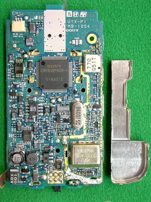
Click to zoom
Application Details
- Equipment Class
- TBF - Licensed Broadcast Transmitter Held to Face
- Date of Grant
- Nov 10, 2005
- Application Purpose
- Original Equipment
- Date of Application
- Nov 10, 2005
- Equipment Note
- UHF Synthesized Transmitter
- Frequency Range
- 758.12500000 - 805.87500000
- Company
- Sony Group Corporation
- Country
- Japan
Documents & Files
Document Text
Text extracted from the exhibit documents filed with the FCC. Open a document above to read the original.
Users Manual
COPY 2-347-712-13(1) 2003 Sony Corporation Operating Instructions Before operating the unit, please read this manual thoroughly and retain it for future reference. UWP-C1/C2/C3 UWP-S1/S2 UWP-X1/X2 Wireless Microphone Package COPY 2 For the AC adapter supplied with UWP-S1/S2 Important Safety Instructions • Read these instructions. • Keep these instructions. • Heed all warnings. • Follow all instructions. • Do not use this apparatus near water. • Clean only with dry cloth. • Do not block any ventilation openings. Install in accordance with the manufacturer’s instructions. • Do not install near any heat sources such as radiators, heat registers, stoves, or other apparatus (including amplifiers) that produce heat. • Do not defeat the safety purpose of the polarized or grounding-type plug. A polarized plug has two blades with one wider than the other. A grounding-type plug has two blades and a third grounding prong. The wide blade or the third prong is provided for your safety. If the provided plug does not fit into your outlet, consult an electrician for replacement of the obsolete outlet. • Protect the power cord from being walked on or pinched particularly at plugs, convenience receptacles, and the point where they exit from the apparatus. • Only use attachments/accessories specified by the manufacturer. • Use only with the cart, stand, tripod, bracket, or table specified by the manufacturer, or sold with the apparatus. When a cart is used, use caution when moving the cart/apparatus combination to avoid injury from tip- over. • Unplug this apparatus during lightning storms or when unused for long periods of time. • Refer all servicing to qualified service personnel. Servicing is required when the apparatus has been damaged in any way, such as power-supply cord or plug is damaged, liquid has been spilled or objects have fallen into the apparatus, the apparatus has been exposed to rain or moisture, does not operate normally, or has been dropped. WARNING To reduce the risk of fire or electrical shock, do not expose this apparatus to rain or moisture. To avoid electrical shock, do not open the cabinet. Refer servicing to qualified personnel only. IMPORTANT The name plate is located on the bottom (AC-911). WARNING This unit has no power switch. When installing the unit, incorporate a readily accessible disconnect device in the fixed wiring, or connect the power cord to socket-outlet which must be provided near the unit and easily accessible. If a fault should occur during operation of the unit, operate the disconnect device to switch the power supply off, or disconnect the power cord. COPY 3 This symbol is intended to alert the user to the presence of uninsulated “dangerous voltage” within the product’s enclosure that may be of sufficient magnitude to constitute a risk of electric shock to persons. This symbol is intended to alert the user to the presence of important operating and maintenance (servicing) instructions in the literature accompanying the appliance. CAUTION To prevent electric shock, match wide blade of plug to wide slot, fully insert. AVERTISSEMENT Afin de réduire les risques d’incendie ou d’électrocution, ne pas exposer cet appareil à la pluie ou à l’humidité. Afin d’écarter tout risque d’électrocution, garder le coffret fermé. Ne confier l’entretien l’appareil qu’à un technicien qualifié. IMPORTANT La plaquette signalétique est posée sur le dessous de l’appareil (AC-911). AVERTISSEMENT Cet appareil ne possède pas d’interrupteur d’alimentation. Lors de l’installation de l’appareil, incorporer un dispositif de coupure facilement accessible dans le câblage fixe ou brancher le cordon d’alimentation dans une prise murale proche de l’appareil et facilement accessible. En cas de problème lors du fonctionnement de l’appareil, enclencher le dispositif de coupure d’alimentation ou dèbrancher le cordon de la prise. ATTENTION Pour éviter tout choc électrique, ajuster la lame large de la fiche sur la fente large et l’insérer à fond. WARNUNG Um die Gefahr von Bränden oder elektrischen Schlägen zu verringern, darf dieses Gerät nicht Regen oder Feuchtigkeit ausgesetzt werden. Um einen elektrischen Schlag zu vermeiden, darf das Gehäuse nicht geöffnet werden. Überlassen Sie Wartungsarbeiten stets nur qualifiziertem Fachpersonal. COPY 4 WICHTIG Am Boden des Geräts befindet sich das Typenschild (AC-911). WARNUNG Dieses Gerät hat keinen Netzschalter. Beim Einbau des Geräts ist daher im Festkabel ein leicht zugänglicher Unterbrecher einzufügen, oder das Netzkabel muss mit einer in der Nähe des Geräts befindlichen, leicht zugänglichen Wandsteckdose verbunden werden. Wenn während des Betriebs eine Funktionsstörung auftritt, ist der Unterbrecher zu betätigen bzw. das Netzkabel abzuziehen, damit die Stromversorgung zum Gerät unterbrochen wird. ACHTUNG Um die Gefahr elektrischer Schläge zu verhindern, immer den Stecker richtig und vollständig einstecken. ATTENZIONE Per ridurre il rischio di incendi o scosse elettriche, non esporre questo apparato alla pioggia o all’umidità. Per evitare scosse elettriche, non aprire l’apparecchio. Per le riparazioni, rivolgersi solo a personale qualificato. IMPORTANTE La targhetta con il nome si trova sul fondo (AC-911). AVVERTENZA Il presente apparecchio non è dotato di interruttore di alimentazione. Quando si installa l’apparecchio, includere nell’impianto fisso un dispositivo di disconnessione rapidamente accessibile o collegare il cavo di alimentazione ad una presa in prossimità dell’apparecchio e che sia facilmente raggiungibile. Nel caso in cui si dovesse verificare una anomalia durante il funzionamento dell’apparecchio, agire sull’interruttore del dispositivo di disconnessione o disconnettere il cavo di alimentazione. ATTENZIONE Per evitare scosse elettriche assicurarsi che la spina sia inserita correttamente e completamente nella presa. ADVERTENCIA Para reducir el riesgo de electrocución, no exponga este aparato a la lluvia ni a la humedad. Para evitar descargas…
Text truncated - open the document above for the full version.
Cover Letter(s)
FCC ID : AK8UTXP1 IC : 409B-UTXP1 Appendix : Designation of Emission Necessary Bandwidth calculation Description of Emission : Sound broad casting Formula : Bn = 2M + 2DK , = (2 x 40000) + (2 x 15000 x 1) = 110000 K = 1 (typically) M = Maximum modulation frequency = 40kHz D = Peak frequency deviation = 15kHz Therefore, Bandwidth = 110kHz , Designation of emission = 110KF3E
Cover Letter(s)
JAPAN QUALITY ASSURANCE ORGANIZATION 21-25, KINUTA 1-CHOME, SETAGAYA-KU, TOKYO 157-8573 JAPAN PHONE +81-3-3416-0111, FAX +81-3-3416-9691 November 4, 2005 Compliance Certification Services 561F Monterey Road Morgan Hill, CA 95037-9001 U. S. A. Subject: Certification Application for Part 74 Equipment Authorization Applicant : Sony Corporation Product : UHF Synthesized Transmitter Model Number : UTX-P1 FCC ID : AK8UTXP1 Dear Sir/Madame: We are submitting application documents through electronic filing for Certification of FCC Part 74 Equipment Authorization with request of confidentiality for the above-mentioned product as an attached request letter. Application fee will be sent you in accordance with your instruction. We shall appreciate your immediate attention and approval. Sincerely, Masanori Takahashi E-Mail: [email protected] EMC Engineering Dept. Japan Quality Assurance Organization FCC ID: AK8UTXP1 LIST OF SUBMITTED DOCUMENTS (November 4, 2005) (1) Exhibit A: Cover Letter and List of Submitted Documents (2) Exhibit B: Authorization Agreement (3) Exhibit C: Confidential Request Letter (4) Exhibit D: Label (5) Exhibit E: Technical Description (6) Exhibit F: Schematics (7) Exhibit G: Block Diagram (8) Exhibit H: Parts List (9) Exhibit J: External Photographs (10) Exhibit K: Internal Photographs (11) Exhibit L: User’s Manual (12) Exhibit M: Test Report (FCC part74) (13) Exhibit N: EUT Setup Photographs
Cover Letter(s)
1 Chris Harvey From:Takahashi Masanori [[email protected]] Sent:Thursday, November 10, 2005 8:53 PM To: Compliance Certification Services Cc:[email protected]; [email protected] Subject:Re: Sony Corporation, FCC ID: AK8UTXP1, Assessment NO.: AN05T5271, Notice#1 Appendix.pdf (6 KB) Exhibit K2-Internal Photograph... Dear Chris Harvey Sorry your waiting, I send to you the document for your request 1&2. Please assessment these document, and reply to me as soon as possible. Sincerely yours, -------------------------------------------------------------- JAPAN QUALITY ASSURANCE ORGANIZATION EMC Engineering Dept. Testing Div. Masanori Takahashi Tel: +81-3-3416-0193 Fax: +81-3-3416-8290 E-mail: [email protected] ------------------------------------------------------------- ----- Original Message ----- From: "Takahashi Masanori" <[email protected]> To: "Compliance Certification Services" <[email protected]> Cc: <[email protected]>; <[email protected]> Sent: Friday, November 11, 2005 9:32 AM Subject: Re: Sony Corporation, FCC ID: AK8UTXP1, Assessment NO.: AN05T5271, Notice#1 > Dear Chris Harvey > > Hello, > Thank you for your reply. > I need the certification today. > I will send to you the additinal document 2 hours later by your > request. Please wait my reply about 2 hours. > > Sincerely yours, > > ----------------------------------------------------------- > JAPAN QUALITY ASSURANCE ORGANIZATION > EMC Engineering Dept. Testing Div. > > Masanori Takahashi > Tel: +81-3-3416-0193 Fax: +81-3-3416-8290 > E-mail: [email protected] > ---------------------------------------------------------- > > 2 > > > ----- Original Message ----- > From: "Compliance Certification Services" <[email protected]> > To: <[email protected]> > Cc: <[email protected]> > Sent: Thursday, November 10, 2005 3:41 PM > Subject: Sony Corporation, FCC ID: AK8UTXP1, Assessment NO.: AN05T5271, > Notice#1 > > > Takahashi-san, > > I have reviewed the above referenced application for TCB Certification > and find that the following items are needed before the review can be completed: > > 1. The internal photographs do not show sufficient detail to show the > component placement on the PC Board, and also has a portion of the > board covered by an RF shield. Please provide additional photographs > with better > resolution showing both sides of the PC Board with the shields > removed. > > 2. Please provide the justification for the necessary bandwidth of > 110K by using Carson's rule (2M+2D). Please confirm that M (Max. > modulation > frequency) is 15 kHz and the value of D (Peak frequency deviation) is 40 > kHz. Please include this justification information in all FCC applications > in the future that require Necessary Bandwidth justification. > > The items indicated above must be submitted before processing can > continue on the above referenced application. Failure to provide the > requested information within 30 days of the original e-mail date may > result in application dismissal and forfeiture of the filing fee. > Also, please note that partial responses increase processing time and > should not be submitted. > Any questions about the content of this correspondence should be > directed to > the e-mail address listed below the name of the sender. > > Best regards, > Chris Harvey > [email protected] > >
External Photos
Page 1 of 2 External Photographs Model No.: UTX-P1 Front side Rear side Front side(UP) Rear side(UP) Left side Right side Page 2 of 2 External Photographs Model No.: UTX-P1 Top side Bottom side Bottom side
ID Label/Location Info
Model No.: UTX-P1 Label Dimensions 44 × 99 × 36 mm (1 3/4 × 4 1 7/16 inches) (w/h/d)
Internal Photos
Internal Photographs Model No.: UTX-P1 Display side Display rear side Display rear side (removed shielded pack)
Test Report
JAPAN QUALITY ASSURANCE ORGANIZATION 21-25, KINUTA 1-CHOME, SETAGAYA-KU, TOKYO 157-8573 JAPAN PHONE (03) 3416-0111, JQA J FAX (03) 3416-9691 JQA File No. : 400-50442 Issue Date : November 2, 2005 Page 1 of 41 EMI TEST REPORT JQA File No. : 400-50442 Model No. : UTX-P1 Type of Equipment : UHF Synthesized Transmitter Regulations Applied : CFR 47 FCC Rules and Regulations Part 74 FCC ID : AK8UTXP1 Applicant : Sony Corporation Address : 6-7-35, Kitashinagawa, Shinagawa-ku, Tokyo 141-0001, Japan Manufacturer : Sony Electronics of Korea Corporation Address : 974-6, Yangduk-dong, Masan, Kyoungsangnam-do, 630-728 Korea Received date of EUT : September 21, 2005 Final Judgment : Passed Test results in this report are obtained in use of equipment that is traceable to National Institute of Advanced Industrial Science and Technology (AIST) of Japan and Communication Research Laboratory (CRL) of Japan. The test results only respond to the tested sample. This report should not be reproduced except in full, without the written approval of JQA EMC Engineering Dept. Testing Div. JQA File No. :400-50442 FCC ID :AK8UTXP1 Model No. :UTX-P1 Issue Date :November 2, 2005 Standard :CFR 47 FCC Rules Part 74 Page 2 of 41 JQA QUALITY ASSURANCE ORGANIZATION TABLE OF CONTENTS Page 1 Documentation 1.1 Test Regulation 3 1.2 General Information 3 1.3 Test Condition 4 – 6 1.4 EUT Modifications / Deviation from Standard 7 1.5 Test results 8 1.6 Summary 9 1.7 Test Configuration / Operation of EUT 10 1.8 EUT Arrangement(Drawing) 11 1.9 Preliminary Test and Test-setup (Drawings) 12 – 17 1.10 EUT Arrangement (Photographs) 18 - 20 2 Test Data 2.1 RF Power Output 21 2.2 Modulation Characteristics 22 – 28 2.3 Radiated Emissions 29 – 30 2.4 Occupied Bandwidth 31 – 34 2.5 Frequency Stability 35 - 36 3 Appendix Test instruments List 37 – 41 JQA File No. :400-50442 FCC ID :AK8UTXP1 Model No. :UTX-P1 Issue Date :November 2, 2005 Standard :CFR 47 FCC Rules Part 74 Page 3 of 41 JQA QUALITY ASSURANCE ORGANIZATION 1 DOCUMENTATION 1.1 TEST REGULATION FCC Rules and Regulations Part 74 Subpart H Low Power Auxiliary Stations Test procedure : RF power output, modulation characteristics, occupied bandwidth, field strength of spurious radiation and frequency stability tests were performed according to the procedures in FCC Rules and Regulations Part 2. 1.2 GENERAL INFORMATION 1.2.1 Test facility : 1) Test Facility located at EMC Engineering Dept. Testing Div. : - No.2 and 3 Anechoic Chambers(3 meters Site). - Shielded Enclosure. 2) EMC Engineering Dept. Testing Div. is recognized under the National Voluntary Laboratory accreditation Program for satisfactory compliance established in title 15, Part 285 Code of Federal Regulations. NVLAP Lab Code : 200189-0 (Effective through : June 30, 2006) 1.2.2 Description of the Equipment Under Test (EUT) : 1) Type of Equipment : UHF Synthesized Transmitter 2) Product Type : Prototype 3) Category : Broadcast Transmitter Held to Face 4) EUT Authorization : Certification 5) FCC ID : AK8UTXP1 6) Trade Name : SONY 7) Model No. : UTX-P1 8) Operating Frequency Range : 758.125 MHz – 805.875 MHz 9) Highest Frequency Used in the EUT : 805.875 MHz 10) Bandwidth : 110 kHz 11) RF Output Power : 50 mW 12) Serial No. : None 13) Date of Manufacture : August, 2005 14) Power Rating : DC 3.0(Battery) 15) EUT Grounding : None 1.2.3 Definitions for symbols used in this test report : x - indicates that the listed condition, standard or equipment is applicable for this report. - indicates that the listed condition, standard or equipment is not applicable for this report. JQA File No. :400-50442 FCC ID :AK8UTXP1 Model No. :UTX-P1 Issue Date :November 2, 2005 Standard :CFR 47 FCC Rules Part 74 Page 4 of 41 JQA QUALITY ASSURANCE ORGANIZATION 1.3 TEST CONDITION 1.3.1 The measurement of the RF power output the Radiated Emission(30 MHz – 1000 MHz) x - was performed in the following test site. - was not applicable. Test location : Safety & EMC Center EMC Engineering Dept. Testing Div. 21-25, Kinuta 1-chome, Setagaya-ku, Tokyo 157-8573, Japan x - Anechoic Chamber No. 2 (3 meters) - Anechoic Chamber No. 3 (3 meters) Validation of Site Attenuation : 1) Last Confirmed Date :March, 2005 2) Interval :1 year Used test instruments : Type Number of test instruments (Refer to Appendix) Test Receiver TR05 Cable CA01 Antenna AN02, AN04, AN06, AN08 RF Amplifier N/A Signal Generator SG03 Power Meter AU03 Power Sensor AU04 JQA File No. :400-50442 FCC ID :AK8UTXP1 Model No. :UTX-P1 Issue Date :November 2, 2005 Standard :CFR 47 FCC Rules Part 74 Page 5 of 41 JQA QUALITY ASSURANCE ORGANIZATION 1.3.2 The measurement of the Radiated Emission(Above 1000 MHz) x - was performed in the following test site. - was not applicable. Test location : Safety & EMC Center EMC Engineering Dept. Testing Div. 21-25, Kinuta 1-chome, Setagaya-ku, Tokyo 157-8573, Japan x - No. 2 site (3 meters) - No. 3 site (3 meters) Validation of Site Attenuation : 1) Last Confirmed Date :March, 2005 2) Interval :1 year Used test instruments : Type Number of test instruments (Refer to Appendix) Test Receiver TR07 Spectrum Analyzer N/A Cable CA11, CA13 Antenna AN10, AN12 RF Amplifier AM09 Band Reject Filter N/A High Pass Filter N/A JQA File No. :400-50442 FCC ID :AK8UTXP1 Model No. :UTX-P1 Issue Date :November 2, 2005 Standard :CFR 47 FCC Rules Part 74 Page 6 of 41 JQA QUALITY ASSURANCE ORGANIZATION 1.3.3 The measurement of the Modulation Characteristics and the Occupied Bandwidth x - was performed. - was not applicable. Used test instruments : Type Number of test instruments (Refer to Appendix) Test Receiver TR07 Spectrum Analyzer N/A Function Generator SG01 FM Linear Detector AU06 Level Meter AU07 Cable CA10 Attenuator AU20 Antenna N/A 1.3.4 The measurement of the Frequency Stability x - was performed. - was not applicable. Used test instruments : Type Number of test instruments (Refer to Appendix) Frequency Counter AU13 Antenna AN04 Cable CA10 Attenuator AU20 Oven AU14 DC Power Supply AU…
Text truncated - open the document above for the full version.
Test Setup Photos
JQA File No. :400-50442 FCC ID :AK8UTXP1 Model No. :UTX-P1 Issue Date :November 2, 2005 Standard :CFR 47 FCC Rules Part 74 Page 18 of 41 JQA QUALITY ASSURANCE ORGANIZATION 1.10 TEST ARRANGEMENT (PHOTOGRAPHS) PHOTOGRAPHS OF EUT CONFIGURATION FOR RADIATED EMISSIONS MEASUREMENT Photograph present configuration with maximum emission - Front view (X axis) - - Right side view (X axis) - JQA File No. :400-50442 FCC ID :AK8UTXP1 Model No. :UTX-P1 Issue Date :November 2, 2005 Standard :CFR 47 FCC Rules Part 74 Page 19 of 41 JQA QUALITY ASSURANCE ORGANIZATION PHOTOGRAPHS OF EUT CONFIGURATION FOR RADIATED EMISSIONS MEASUREMENT Photograph present configuration with maximum emission - Back view (X axis) - - Left side view (X axis) - JQA File No. :400-50442 FCC ID :AK8UTXP1 Model No. :UTX-P1 Issue Date :November 2, 2005 Standard :CFR 47 FCC Rules Part 74 Page 20 of 41 JQA QUALITY ASSURANCE ORGANIZATION PHOTOGRAPHS OF EUT CONFIGURATION FOR RADIATED EMISSIONS MEASUREMENT Photograph present configuration with maximum emission - Front view (Z axis) -
Contact Information
Applicant
Kazuyuki Hori(Chief EMC/RF Compliance Specialist)
Test Firm
Japan Qlty. Assur. Org. Kitakansai Testing CenterHiroyuki Nakamura
Technical Specifications
| # | Rule Parts | Frequency Range | Power Output | Emission | Tolerance |
|---|---|---|---|---|---|
| 1 | 74.861 | 758.125 MHz - 805.875 MHz | 43.00 mW | 110KF3E | 0.0050000000 % |
Other Applications from Sony Group Corporation
AK8WW81782
Aug 21, 2026Radio Equipment
Equipment Class
DSS - Part 15 Spread Spectrum TransmitterAK8CFIZCP2
Aug 03, 2026Wireless Controller
Equipment Class
DSS - Part 15 Spread Spectrum TransmitterAK8OEV321MUH
Apr 14, 2026LCD Monitor
Equipment Class
JAD - Part 15 Class A Digital DeviceAK8OEV431MUH
Apr 14, 2026LCD Monitor
Equipment Class
JAD - Part 15 Class A Digital DeviceAK8OEV271MUH
Apr 14, 2026LCD Monitor
Equipment Class
JAD - Part 15 Class A Digital Device