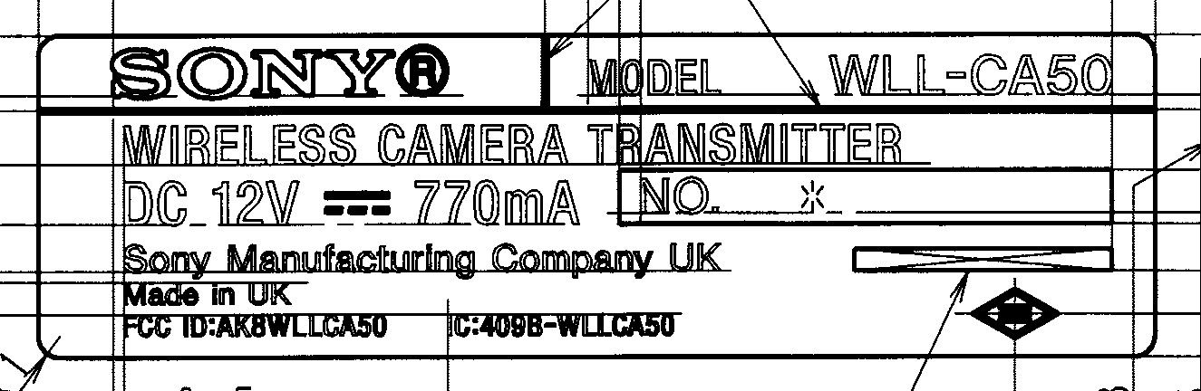
AK8WLLCA50Wireless Camera Transmitter
Sony Group Corporation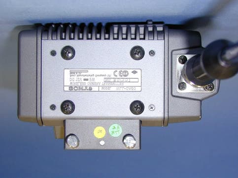
Click to zoom
Application Details
- Equipment Class
- DSS - Part 15 Spread Spectrum Transmitter
- Date of Grant
- Apr 08, 2003
- Application Purpose
- Original Equipment
- Date of Application
- Jan 15, 2003
- Equipment Note
- Wireless Camera Transmitter
- Frequency Range
- 2406.00000000 - 2470.00000000
- Company
- Sony Group Corporation
- Country
- Japan
Documents & Files
Document Text
Text extracted from the exhibit documents filed with the FCC. Open a document above to read the original.
Cover Letter(s)
To: Diane Poole [email protected] FCC Application Processing Branch Re: FCC ID AK8WLLCA50 Applicant: Sony Corporation Correspondence Reference Number: 24908 731 Confirmation Number: EA660956 Reply to your comments 1. Demonstration that probe calibration is appropriate for wideband OFDM/QAM modulation tested. We are understanding that the coded OFDM (Orthogonal Frequency Division Multiplex) may generally generate a high peak power at a instant when each phase of multiple carriers are in phase. (1) WLL-CA50 The ALC (Automatic Level Control) are employed in the WLL-CA50 RF unit controls the RF output and works to keep it constant by use of the feedback loop. So instantaneous peak outputs power generated by the coded OFDM of WLL-CA50 are suppressed by 3 times of the average power by the use of ALC. WLL-CA50.pdf file shows the block diagram. (2) E-Field Probe (ETV3DV6) The calibration data of dosimetric E-Field Probe (ET3DV6) has been already submitted at this application. The frequency response and dynamic range of the E-Field probe are shown. They show the flatness of the response from 0.3 to 3.0 GHz and the wide dynamic range to 100 mW/g within linearity +-0.2dB. (3) Evaluation result of SAR The peak power of OFDM is high value. But actually the average power of WLL-CA50 was around 25mW. And the measured figures of SAR were a normal range which we have experienced with DSSS LAN Card. We believe that the probe calibration is appropriate for wideband OFDM/QAM modulation tested. 2. SAR values with a small gap between the antenna and phantom such as 1.5 cm. Testing with the worst two configurations is sufficient. A 0 gap measurement may artificially spread out SAR hot spot due to impedance loading through close coupling to the liquid. Although the spread of SAR hot spot due to close coupling is supposed, our experiment has shown that the 0 gap condition was the highest SAR value from 0 cm gap to 3 cm gap this time. This experiment data is submitted as SAR experiment.pdf files. Also we can explain the 0 gap condition was the worst SAR value by using the evaluation report of DSS LAN card. Therefore, our evaluation data shows the most severe SAR condition is the 0 gap in this application. Kanako Sanda (Ms.) A-Pex International Co., Ltd.
External Photos
External Photos Sony Corporation FCC ID: AK8WLLCA50 < Front > < Back > External Photos Sony Corporation FCC ID: AK8WLLCA50 < Right > < Left > External Photos Sony Corporation FCC ID: AK8WLLCA50 < Top > < Bottom > External Photos Sony Corporation FCC ID: AK8WLLCA50 < Front of Transmitter > < Back of Transmitter > External Photos Sony Corporation FCC ID: AK8WLLCA50 < Top of Transmitter > < Bottom of Transmitter > External Photos Sony Corporation FCC ID: AK8WLLCA50 < Right of Transmitter > < Left of Transmitter > External Photos Sony Corporation FCC ID: AK8WLLCA50 < Antenna part of Transmitter >
Internal Photos
Internal Photos Sony Corporation FCC ID: AK8WLLCA50 < Internal of Transmitter > Internal Photos Sony Corporation FCC ID: AK8WLLCA50 < Outside of Transmitter and Front side of PCB > < Outside of Transmitter and Back side of PCB > RF Unit Power Supply System Control Digital signal process Internal Photos Sony Corporation FCC ID: AK8WLLCA50 < Front side of RF Part with Shield > < Back side of RF Part with Shield > Internal Photos Sony Corporation FCC ID: AK8WLLCA50 < Front side of RF Part without Shield > < Back side of RF Part without Shield >
RF Exposure Info
Test report No. : 23EE0029-HO Page : 2 of 70 Issued date : January 14,2003 FCC ID :AK8WLLCA50 A-PEX International Co., Ltd. EMC Head Office Division. 4383-326 Asama-cho, Ise-shi, Mie-ken 516-0021 JAPAN Telephone: +81 596 24 8116 Facsimile: +81 596 24 8124 CONTENTS PAGE SECTION 1 : Client information 3 SECTION 2 : Equipment under test (E.U.T.) 3 SECTION 3 : Requirements for compliance testing defined by the FCC 4 SECTION 4 : Dosimetric assessment setup 4 SECTION 5 : Test system specifications 7 SECTION 6 : Test setup of EUT 8 SECTION 7 : Measurement uncertainty 9 SECTION 8 : Simulated tissue liquid parameter 10 SECTION 9 : System validation data 11 SECTION 10 : Evaluation procedure 12 SECTION 11 : Exposure limit 13 SECTION 12 : SAR Measurement results 14 SECTION 13 : Equipment & calibration information 16 SECTION 14 : References 17 SECTION 15 : APPENDIX 17 APPENDIX 1 : Photographs of test setup APPENDIX 2 : SAR Measurement data APPENDIX 3 : Validation Measurement data APPENDIX 4 : System Validation Dipole (D2450V2,S/N: 713) APPENDIX 5 : Dosimetric E-Field Probe Calibration(ET3DV6,S/N: 1684) Test report No. : 23EE0029-HO Page : 3 of 70 Issued date : January 14,2003 FCC ID :AK8WLLCA50 A-PEX International Co., Ltd. EMC Head Office Division. 4383-326 Asama-cho, Ise-shi, Mie-ken 516-0021 JAPAN Telephone: +81 596 24 8116 Facsimile: +81 596 24 8124 SECTION 1 : Client information Company Name : Sony Corporation Brand Name : SONY Address : 6-7-35 Kitasinagawa Sinagawa ñku Tokyo,141-0001,Japan Telephone Number : +81-3-5795-8716 Facsimile Number : +81-3-5795-8981 Contact Person : Saori Takada SECTION 2 : Equipment under test (E.U.T.) 2.1 Identification of E.U.T. APPLICANT : Sony Corporation Type of Equipment : Wireless Camera Transmitter Model No. : WLL-CA50 Serial No. : 10001 Rating : DC11.0V~17.0V Country of Manufacture : UK Receipt Date of Sample : December/20/2002 Condition of EUT : Production prototype Tx Frequency : 2406MHz~2470MHz Modulation : 16QAM-OFDM , QPSK-OFDM Max.Output Power Tested : 24.1dBm Peak Conducted Antenna Type : Dipole Antenna Battery option : Only one model with EUT Category Identified : Portable device Test report No. : 23EE0029-HO Page : 4 of 70 Issued date : January 14,2003 FCC ID :AK8WLLCA50 A-PEX International Co., Ltd. EMC Head Office Division. 4383-326 Asama-cho, Ise-shi, Mie-ken 516-0021 JAPAN Telephone: +81 596 24 8116 Facsimile: +81 596 24 8124 SECTION 3 : Requirements for compliance testing defined by the FCC The US Federal Communications Commission has released the report and order ìGuidelines for Evaluating the Environmental Effects of RF Radiation", ET Docket No. 93-62 in August 1996. The order requires routine SAR evaluation prior to equipment authorization of portable transmitter devices, including portable telephones. For consumer products, the applicable limit is 1.6 mW/g for an uncontrolled environment and 8.0 mW/g for an occupational/controlled environment as recommended by the ANSI/IEEE standard C95.1-1992. According to the Supplement C of OET Bulletin 65 ìEvaluating Compliance with FCC Guide-lines for Human Exposure to Radio frequency Electromagnetic Fields", released on Jun 29, 2001 by the FCC, the device should be evaluated at maximum output power (radiated from the antenna) under ìworst-caseî conditions for normal or intended use, incorporating normal antenna operating positions, device peak performance frequencies and positions for maximum RF energy coupling. 1 Specific Absorption Rate (SAR) is a measure of the rate of energy absorption due to exposure to an RF transmitting source (wireless portable device). 2 IEEE/ANSI Std. C95.1-1992 limits are used to determine compliance with FCC ET Docket 93-62. SECTION 4 : Dosimetry assessment setup These measurements were performed with the automated near-field scanning system DASY3 from Schmid & Partner Engineering AG (SPEAG). The system is based on a high precision robot (working range greater than 0.9 m), which positions the probes with a positional repeatability of better than +/- 0.02 mm. Special E- and H-field probes have been developed for measurements close to material discontinuity, the sensors of which are directly loaded with a Schottky diode and connected via highly resistive lines to the data acquisition unit. The SAR measurements were conducted with the dosimetry probe ET3DV6, SN: 1684 (manufactured by SPEAG), designed in the classical triangular configuration and optimized for dosimetric evaluation. The probe has been calibrated according to the procedure described in [2] with accuracy of better than +/-10%. The spherical isotropy was evaluated with the procedure described in [3] and found to be better than +/-0.25 dB. The phantom used was the SAM Twin Phantom as described in FCC supplement C, IEE P1528 and CENELEC EN50361. Test report No. : 23EE0029-HO Page : 5 of 70 Issued date : January 14,2003 FCC ID :AK8WLLCA50 A-PEX International Co., Ltd. EMC Head Office Division. 4383-326 Asama-cho, Ise-shi, Mie-ken 516-0021 JAPAN Telephone: +81 596 24 8116 Facsimile: +81 596 24 8124 4.1 Configuration and peripherals The DASY3 system for performing compliance tests consist of the following items: 1. A standard high precision 6-axis robot (St‰ubli RX family) with controller and software. 2. An arm extension for accommodating the data acquisition electronics (DAE). 3. A dosimetric probe, i.e., an isotropic E-field probe optimized and calibrated for usage in tissue simulating liquid. The probe is equipped with an optical surface detector system. 4. A data acquisition electronic (DAE), which performs the signal amplification, signal multiplexing, AD-conversion, offset measurements, mechanical surface detection, collision detection, etc. The unit is battery powered with standard or rechargeable batteries. The signal is optically transmitted to the EOC. 5. A unit to operate the optical surface detector, which is connected to the EOC. 6. The Electro-optical coupler (EOC) performs the conversion from the optica…
Text truncated - open the document above for the full version.
RF Exposure Info
Test report No. : 23EE0029-HO Page : 21 of 70 Issued date : January 14,2003 FCC ID :AK8WLLCA50 A-PEX International Co., Ltd. EMC Head Office Division. 4383-326 Asama-cho, Ise-shi, Mie-ken 516-0021 JAPAN Telephone: +81 596 24 8116 Facsimile: +81 596 24 8124 APPENDIX 2 : SAR Measurement data
RF Exposure Info
Test report No. : 23EE0029-HO Page : 45 of 70 Issued date : January 14,2003 FCC ID :AK8WLLCA50 A-PEX International Co., Ltd. EMC Head Office Division. 4383-326 Asama-cho, Ise-shi, Mie-ken 516-0021 JAPAN Telephone: +81 596 24 8116 Facsimile: +81 596 24 8124 APPENDIX 3 : Validation Measurement data
RF Exposure Info
Test report No. : 23EE0029-HO Page : 47 of 70 Issued date : January 14,2003 FCC ID :AK8WLLCA50 A-PEX International Co., Ltd. EMC Head Office Division. 4383-326 Asama-cho, Ise-shi, Mie-ken 516-0021 JAPAN Telephone: +81 596 24 8116 Facsimile: +81 596 24 8124 APPENDIX 4 : System Validation Dipole (D2450V2,S/N: 713)
RF Exposure Info
Test report No. : 23EE0029-HO Page : 57 of 70 Issued date : January 14,2003 FCC ID :AK8WLLCA50 A-PEX International Co., Ltd. EMC Head Office Division. 4383-326 Asama-cho, Ise-shi, Mie-ken 516-0021 JAPAN Telephone: +81 596 24 8116 Facsimile: +81 596 24 8124 APPENDIX 5 : Dosimetric E-Field Probe Calibration(ET3DV6,S/N: 1684)
Test Report
FCC ID : AK8WLLCA50 Test report No. : 23CE0026-YK-1 Page : 2 of 70 Issued date : November 29, 2002 A-Pex International Co., Ltd. YAMAKITA LAB. 907 Kawanishi, Yamakita-machi, Ashigarakami-gun, Kanagawa-ken, 258-0124 JAPAN Telephone: +81 465 77 1011 Facsimile: +81 465 77 2112 MF060b(23.04.02) Table of Contents Page 1 GENERAL INFORMATION 3 1.1 Tested Methodology 3 1.2 Test Facility 3 2 PRODUCT DESCRIPTION 4 3 SYSTEM TEST CONFIGURATION 5 3.1 Justification 5 3.2.Configuration of Tested System 6 4 MEASUREMENT UNCERTAINTY 7 5 SUMMARY OF TEST 8 5.1 §15.207 Conducted Emissions 8 5.2 §15.247(a)(2) 6dB Bandwidth (Antenna port Conducted) 8 5.3 §15.247(b)(3) Maximum Peak Out Put Power (Antenna port Conducted) 8 5.4 §15.247(c) Out of Band Emissions (Radiated) 9 5.5 §15.247(c) Out of Band Emissions (Antenna Port Conducted) 9 5.6 §15.247(d) Power Density (Antenna Port Conducted) 9 Contents of Appendixes 10 APPENDIX 1: Photographs of test setup 11 APPENDIX 2: Test Data 14 APPENDIX 3: Test instruments 70 FCC ID : AK8WLLCA50 Test report No. : 23CE0026-YK-1 Page : 3 of 70 Issued date : November 29, 2002 A-Pex International Co., Ltd. YAMAKITA LAB. 907 Kawanishi, Yamakita-machi, Ashigarakami-gun, Kanagawa-ken, 258-0124 JAPAN Telephone: +81 465 77 1011 Facsimile: +81 465 77 2112 MF060b(23.04.02) 1 GENERAL INFORMATION Applicant Company Name : Sony Corporation Brand Name : SONY Address : 6-7-35 Kitashinagawa, Shinagawa-ku, Tokyo-to, 141-0001 JAPAN Telephone Number : +81 3 5795 5938 Facsimile Number : +81 3 5795 5955 Contact Person : Satoshi Yamamoto Type of Equipment : Wireless Camera Transmitter Model No. : WLL-CA50 Serial No. : 10001 Rating : DC9.0V (Battery: DC10.5-17V)/ AC Adaptor: AC100-240V) Receipt Date of Sample : November 6, 2002 Condition of EUT : Production prototype Regulation(s) : FCC Part15 Subpart C, Section 15.247 Test Site : A-Pex Yamakita No.1 Open Test Site 1.1 Tested Methodology The measurements were performed according to the procedures in ANSI C63.4 (2000). These tests were also referred to FCC 97-114 “Guidance on Measurement for Direct Spread Spectrum Systems”. 1.2 Test Facility This site has been fully described in a report submitted to FCC office, and accepted on September 20, 2002 (Registration No.: 95486). NVLAP Lab. code : 200441-0 FCC ID : AK8WLLCA50 Test report No. : 23CE0026-YK-1 Page : 4 of 70 Issued date : November 29, 2002 A-Pex International Co., Ltd. YAMAKITA LAB. 907 Kawanishi, Yamakita-machi, Ashigarakami-gun, Kanagawa-ken, 258-0124 JAPAN Telephone: +81 465 77 1011 Facsimile: +81 465 77 2112 MF060b(23.04.02) 2 PRODUCT DESCRIPTION Sony Corporation, Model: WLL-CA50 (referred to as the EUT in this report) is a Wireless Camera Transmitter. The clock frequencies used in EUT : 18.285714MHz (Signal) 20MHz (CPU) 27MHz (Signal) 30MHz (CPU) Frequency characteristics : 2406MHz through 2470MHz Number of channels/ channel spacing : 65 channels/ 1MHz step and 12MHz spacing Modulation : 16QAM-OFDM, QPSK-OFDM Antenna type : Dipole Antenna Gain : 4.0dBi Operating Voltage : DC9.0V (Battery: DC10.5-17V)/ AC Adaptor: AC100-240V) WLL-CA50 is a transmitter for MPEG wireless camera system which provides high quality picture and audio as well as stable RF link with MPEG-2 compression and advanced digital modulation technology using COFDM. *FCC Part15.31 (e) The host device DNW-9WS (Digital camcorder) provides the Transmitter module with stable power supply (DC9.0V), and the power is not changed when voltage of the Digital camcorder (DC10.5-17V) is varied. Therefore, the Transmitter module complies power supply regulation. *FCC Part15.203 The antenna of WLL-CA50 doesn’t use a standard antenna jack or electrical connector, therefore the Wireless camera transmitter complies FCC Part15.203 Antenna requirement. FCC ID : AK8WLLCA50 Test report No. : 23CE0026-YK-1 Page : 5 of 70 Issued date : November 29, 2002 A-Pex International Co., Ltd. YAMAKITA LAB. 907 Kawanishi, Yamakita-machi, Ashigarakami-gun, Kanagawa-ken, 258-0124 JAPAN Telephone: +81 465 77 1011 Facsimile: +81 465 77 2112 MF060b(23.04.02) 3 SYSTEM TEST CONFIGURATION 3.1 Justification The system was configured in typical fashion (as a customer would normally use it) for testing. Test mode: 16QAM-OFDM 1. High power mode Transmitting Low channel : 2406MHz Middle channel : 2442MHz High channel : 2470MHz 2. Low power mode Transmitting Low channel : 2406MHz Middle channel : 2442MHz High channel : 2470MHz 3. Standby mode The EUT was tested in all three orthogonal planes in order to determine worst case emissions. Channels at 2406 MHz, 2442 MHz and 2470 MHz were tested and investigated from 30 MHz to 26 GHz. Data for all three channels are presented in this report. The COFDM system employed in the EUT has an ability to provide two different data rates by using QPSK and 16 QAM modulations. These two modulation schemes did not change spectrum envelopes of the EUT at conducted measurement at the antenna terminal. As a result the 16 QAM-OFDM modulation with highest data rate was used for final measurements. FCC ID : AK8WLLCA50 Test report No. : 23CE0026-YK-1 Page : 6 of 70 Issued date : November 29, 2002 A-Pex International Co., Ltd. YAMAKITA LAB. 907 Kawanishi, Yamakita-machi, Ashigarakami-gun, Kanagawa-ken, 258-0124 JAPAN Telephone: +81 465 77 1011 Facsimile: +81 465 77 2112 MF060b(23.04.02) 3.2 Configuration of Tested System Front View *Cabling was taken into consideration and test data was taken under worse case conditions. Top View *Cabling was taken into consideration and test data was taken under worse case conditions. Description of EUT and support equipment No. Item Model number Serial number Manufacturer FCC ID Remarks A Transmitter WLL-CA50 10001 Sony Corporation AK8WLLCA50 EUT B AC Adaptor AC-550 14562 Sony Corporation - - C Digital Camcorder DNW-9WS 3002 Sony Corporation - - List of cables used No. Name Length (m) Shield Backshell material 1 AC Cable 2.0 Unshielded Polyvinyl chloride 2 DC Cable 2.1 Unshielded Polyvinyl chloride C A B 2 1 AC120…
Text truncated - open the document above for the full version.
Test Report
Page : 1 of 37 A-PEX International Co., Ltd. EMC Head Office Division. 4383-326 Asama-cho, Ise-shi, Mie-ken 516-0021 JAPAN Telephone: +81 596 24 8116 Facsimile: +81 596 24 8124 MF058b(23.04.02) SAR EXPERIMENT REPORT Test standard : FCC47CFR 2.1093 FCC OET Bulletin 65, Supplement C SAR value from 0 cm gap to 3 cm gap Date of test: March 14,2003 Tested by: Miyo Ikuta EMC Head Office Division Approved by: Tetsuo Maeno Site Manager of EMC Head Office Division Page : 2 of 37 A-PEX International Co., Ltd. EMC Head Office Division. 4383-326 Asama-cho, Ise-shi, Mie-ken 516-0021 JAPAN Telephone: +81 596 24 8116 Facsimile: +81 596 24 8124 CONTENTS PAGE SECTION 1 : Identification of Dipole 3 SECTION 2 : Requirements for compliance testing defined by the FCC 3 SECTION 3 : Dosimetric assessment setup 3 SECTION 4 : Test system specifications 6 SECTION 5 : Test setup of EUT 7 SECTION 6 : Measurement uncertainty 8 SECTION 7 : Simulated tissue liquid parameter 9 SECTION 8 : System validation data 10 SECTION 9 : Evaluation procedure 11 SECTION 10 : SAR Measurement results 12 SECTION 11 : Equipment & calibration information 14 SECTION 12 : References 15 SECTION 13 : APPENDIX 15 APPENDIX 1 : Photographs of test setup APPENDIX 2 : SAR Measurement data APPENDIX 3 : Validation Measurement data Page : 3 of 37 A-PEX International Co., Ltd. EMC Head Office Division. 4383-326 Asama-cho, Ise-shi, Mie-ken 516-0021 JAPAN Telephone: +81 596 24 8116 Facsimile: +81 596 24 8124 SECTION 1 : Identification of Dipole Manufacture : Schmid & Partner Engineering AG Type of Equipment : Dipole Antenna Frequency : 2450MHz Model No. : D2450V2 Serial No. : 713 Forward Conducted Power : 250mW SECTION 2 : Requirements for compliance testing defined by the FCC The US Federal Communications Commission has released the report and order “Guidelines for Evaluating the Environmental Effects of RF Radiation", ET Docket No. 93-62 in August 1996. The order requires routine SAR evaluation prior to equipment authorization of portable transmitter devices, including portable telephones. For consumer products, the applicable limit is 1.6 mW/g for an uncontrolled environment and 8.0 mW/g for an occupational/controlled environment as recommended by the ANSI/IEEE standard C95.1-1992. According to the Supplement C of OET Bulletin 65 “Evaluating Compliance with FCC Guide-lines for Human Exposure to Radio frequency Electromagnetic Fields", released on Jun 29, 2001 by the FCC, the device should be evaluated at maximum output power (radiated from the antenna) under “worst-case” conditions for normal or intended use, incorporating normal antenna operating positions, device peak performance frequencies and positions for maximum RF energy coupling. 1 Specific Absorption Rate (SAR) is a measure of the rate of energy absorption due to exposure to an RF transmitting source (wireless portable device). 2 IEEE/ANSI Std. C95.1-1992 limits are used to determine compliance with FCC ET Docket 93-62. SECTION 3 : Dosimetry assessment setup These measurements were performed with the automated near-field scanning system DASY3 from Schmid & Partner Engineering AG (SPEAG). The system is based on a high precision robot (working range greater than 0.9 m), which positions the probes with a positional repeatability of better than +/- 0.02 mm. Special E- and H-field probes have been developed for measurements close to material discontinuity, the sensors of which are directly loaded with a Schottky diode and connected via highly resistive lines to the data acquisition unit. The SAR measurements were conducted with the dosimetry probe ET3DV6, SN: 1684 (manufactured by SPEAG), designed in the classical triangular configuration and optimized for dosimetric evaluation. The probe has been calibrated according to the procedure described in [2] with accuracy of better than +/-10%. The spherical isotropy was evaluated with the procedure described in [3] and found to be better than +/-0.25 dB. The phantom used was the SAM Twin Phantom as described in FCC supplement C, IEE P1528 and CENELEC EN50361. Page : 4 of 37 A-PEX International Co., Ltd. EMC Head Office Division. 4383-326 Asama-cho, Ise-shi, Mie-ken 516-0021 JAPAN Telephone: +81 596 24 8116 Facsimile: +81 596 24 8124 3.1 Configuration and peripherals The DASY3 system for performing compliance tests consist of the following items: 1. A standard high precision 6-axis robot (Stäubli RX family) with controller and software. 2. An arm extension for accommodating the data acquisition electronics (DAE). 3. A dosimetric probe, i.e., an isotropic E-field probe optimized and calibrated for usage in tissue simulating liquid. The probe is equipped with an optical surface detector system. 4. A data acquisition electronic (DAE), which performs the signal amplification, signal multiplexing, AD-conversion, offset measurements, mechanical surface detection, collision detection, etc. The unit is battery powered with standard or rechargeable batteries. The signal is optically transmitted to the EOC. 5. A unit to operate the optical surface detector, which is connected to the EOC. 6. The Electro-optical coupler (EOC) performs the conversion from the optical into a digital electric signal of the DAE. The EOC is connected to the PC plug-in card. 7. The functions of the PC plug-in card based on a DSP is to perform the time critical task such as signal filtering, surveillance of the robot operation fast movement interrupts. 8. A computer operating Windows 95 or larger 9. DASY3 software 10. Remote control with teaches pendant and additional circuitry for robot safety such as warning lamps, etc. 11. The SAM phantom enabling testing left-hand and right-hand usage. 12. The device holder for handheld EUT. 13. Tissue simulating liquid mixed according to the given recipes (see Application Note). 14. System validation dipoles to validate the proper functioning of the system. Page : 5 of 37 A-PEX International Co., Ltd. EMC Head Office Division. 4383-326 Asama-cho, …
Text truncated - open the document above for the full version.
Test Report
Page : 23 of 37 A-PEX International Co., Ltd. EMC Head Office Division. 4383-326 Asama-cho, Ise-shi, Mie-ken 516-0021 JAPAN Telephone: +81 596 24 8116 Facsimile: +81 596 24 8124 APPENDIX 2 : SAR Measurement data
Test Report
Page : 36 of 37 A-PEX International Co., Ltd. EMC Head Office Division. 4383-326 Asama-cho, Ise-shi, Mie-ken 516-0021 JAPAN Telephone: +81 596 24 8116 Facsimile: +81 596 24 8124 APPENDIX 3 : Validation Measurement data
Test Setup Photos
FCC ID : AK8WLLCA50 Test report No. : 23CE0026-YK-1 Page : 11 of 70 Issued date : November 29, 2002 A-Pex International Co., Ltd. YAMAKITA LAB. 907 Kawanishi, Yamakita-machi, Ashigarakami-gun, Kanagawa-ken, 258-0124 JAPAN Telephone: +81 465 77 1011 Facsimile: +81 465 77 2112 MF060b(23.04.02) Conducted emission FCC ID : AK8WLLCA50 Test report No. : 23CE0026-YK-1 Page : 12 of 70 Issued date : November 29, 2002 A-Pex International Co., Ltd. YAMAKITA LAB. 907 Kawanishi, Yamakita-machi, Ashigarakami-gun, Kanagawa-ken, 258-0124 JAPAN Telephone: +81 465 77 1011 Facsimile: +81 465 77 2112 MF060b(23.04.02) Radiated emission FCC ID : AK8WLLCA50 Test report No. : 23CE0026-YK-1 Page : 13 of 70 Issued date : November 29, 2002 A-Pex International Co., Ltd. YAMAKITA LAB. 907 Kawanishi, Yamakita-machi, Ashigarakami-gun, Kanagawa-ken, 258-0124 JAPAN Telephone: +81 465 77 1011 Facsimile: +81 465 77 2112 MF060b(23.04.02) Pre check of worse-case position X axis Y axis
Contact Information
Applicant
Kazuyuki Hori(Chief EMC/RF Compliance Specialist)
Technical Contact
A-Pex International Co., Ltd.Toyokazu Imamura
[email protected]+81-465-77-1011
907 Kawanishi, Yamakita-machi · Ashigaragami-gun, Kanagawa-ken · Japan
Non-Technical Contact
A-Pex International Co., Ltd.Kanako Sanda
[email protected]+81-596-24-8116
Test Firm
UL Japan, IncMitsuru Fujimura
Technical Specifications
| # | Rule Parts | Frequency Range | Power Output |
|---|---|---|---|
| 1 | 15C | 2.41 GHz - 2.47 GHz | 245.00 mW |
Other Applications from Sony Group Corporation
AK8WW81782
Aug 21, 2026Radio Equipment
Equipment Class
DSS - Part 15 Spread Spectrum TransmitterAK8CFIZCP2
Aug 03, 2026Wireless Controller
Equipment Class
DSS - Part 15 Spread Spectrum TransmitterAK8OEV321MUH
Apr 14, 2026LCD Monitor
Equipment Class
JAD - Part 15 Class A Digital DeviceAK8OEV431MUH
Apr 14, 2026LCD Monitor
Equipment Class
JAD - Part 15 Class A Digital DeviceAK8OEV271MUH
Apr 14, 2026LCD Monitor
Equipment Class
JAD - Part 15 Class A Digital Device