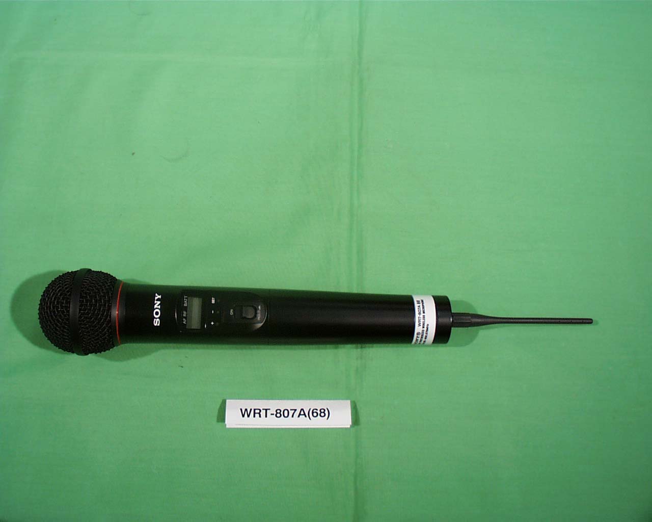
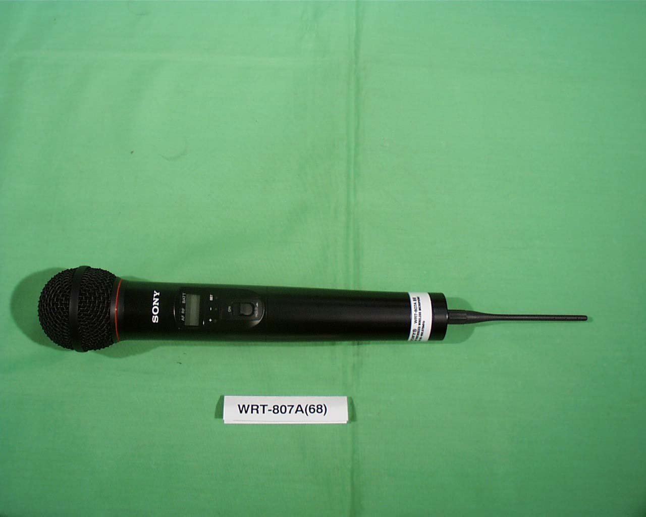
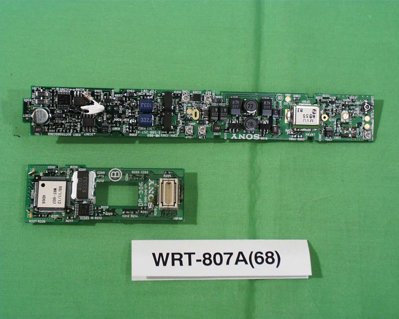
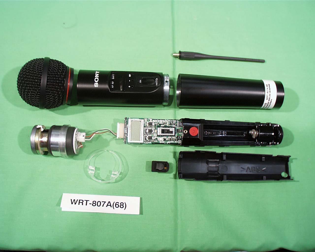
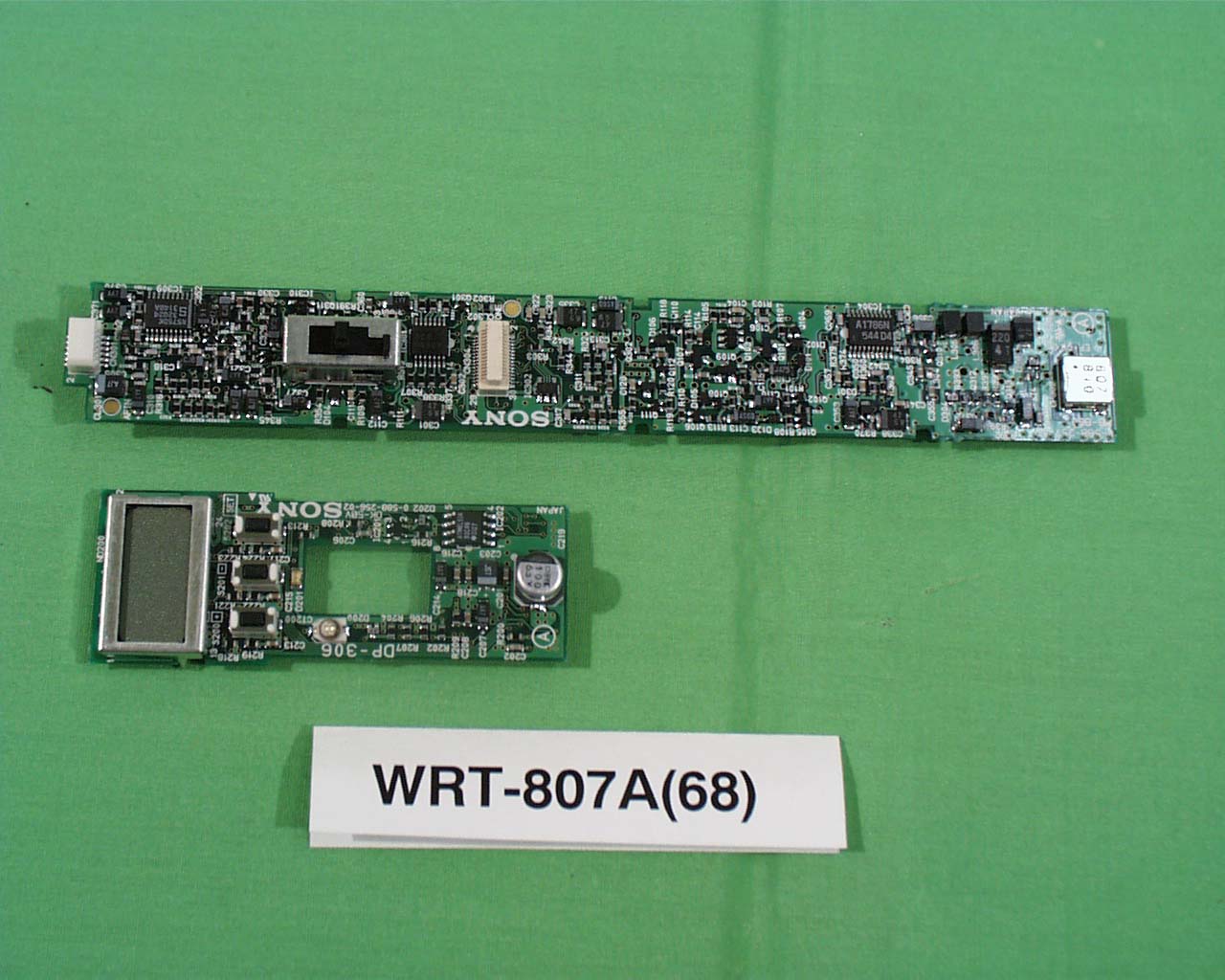
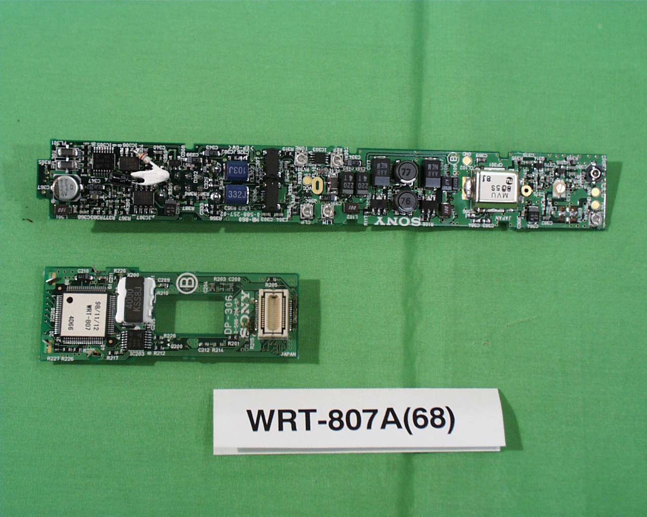
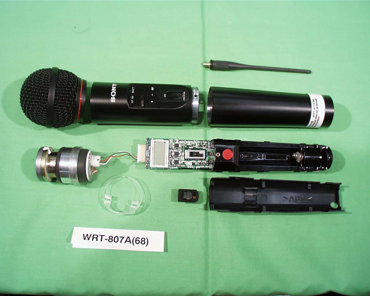
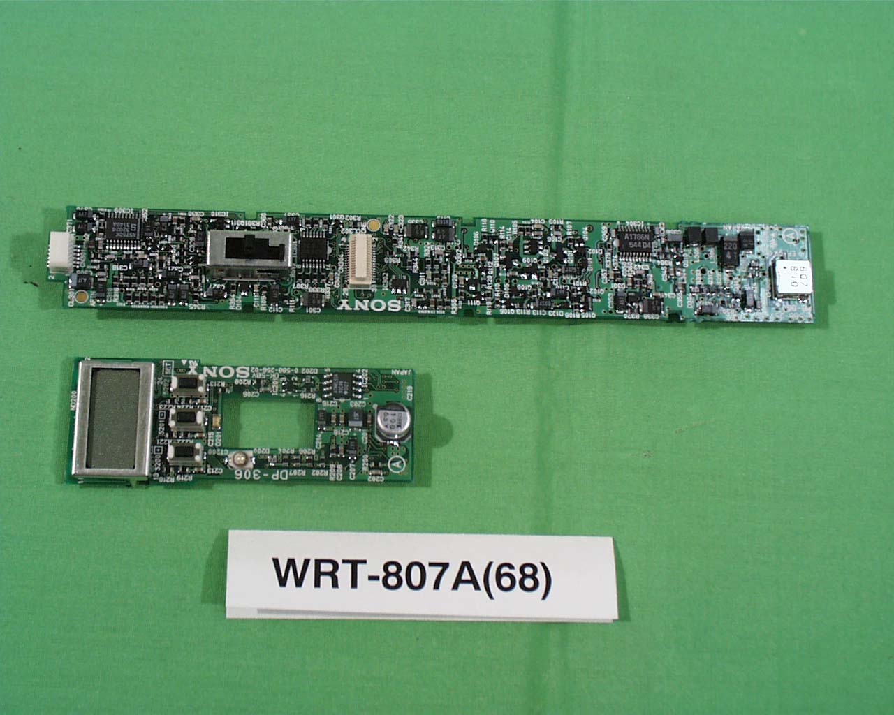
AK8WRT807A68UHF Synthesized Wireless Microphone
Sony Group Corporation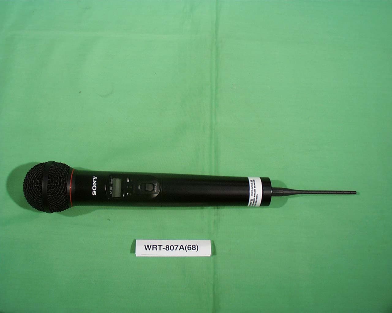
Click to zoom
Application Details
- Equipment Class
- TNF - Licensed Non-Broadcast Transmitter Held to Face
- Date of Grant
- Jun 03, 1999
- Application Purpose
- Original Equipment
- Date of Application
- Feb 16, 1999
- Equipment Note
- UHF Synthesized Wireless Microphone
- Frequency Range
- 794.12500000 - 805.87500000
- Company
- Sony Group Corporation
- Country
- Japan
Documents & Files
Document Text
Text extracted from the exhibit documents filed with the FCC. Open a document above to read the original.
Users Manual
3-866-377-11 (1) WRT-807A UHF Synthesized Wireless Microphone Operating Instructions Manual de instrucciones Mode d’emploi Wireless Channel Lists Listas de canales inalámbricos Listes des canaux sans fil 1999 by Sony Corporation [U64] [U66][U68] US EN FR Owner’s Record The model and serial numbers are located at the rear of the unit. Record the serial number in the space provided below. Refer to these numbers whenever you call upon your Sony dealer regarding this product. Model No. WRT-807ASerial No. Notice for customers in the U.S.A. Use of Sony wireless devices is regulated by the Federal Communications Commission as described in Part 74 subpart H of the FCC regulations and users authorized thereby are required to obtain an appropriate licence. You are cautioned that any changes or modifications not expressly approved in this manual could void your authority to operate this equipment. Notice for customers in Canada: Use of Sony wireless devices is regulated by the Industry Canada as described in their Radio Standard Specification RSS-123. A licence is normally required. The local district office of Industry Canada should therefore be contacted. When the operation of the device is within the broadcast band, the licence is issued on no-interference, no-protection basis with respect to broadcast signals. Avis pour les clients au Canada: L’usage des appareils sans-fil Sony est réglé par l’Industrie Canada comme décrit dans leur Cahier des Normes Radioélectriques CNR-123. Une licence est normalement requise. Le bureau de l’Industrie Canada doit être contacté. Lorsque l’opération de l’appareil est dans les limites de la bande de radiodiffusion, la licence est émanée sur la base de non-interférence, non-protection avec les signaux de radiodiffusion. 3 US Table of Contents English English US Precautions ................................................................ 1 Introduction ............................................................... 2 Features ............................................................. 2 Parts Identification .................................................... 4 Power Supply ............................................................ 7 Settings ...................................................................... 8 Initiating Setting Mode ..................................... 8 Changing the Transmitting Channel ................. 8 Changing the Input Attenuation Setting .......... 10 Resetting the Accumulated Battery Use Time Indication ......................................... 11 Troubleshooting ...................................................... 12 Specifications .......................................................... 14 Error Messages ....................................................... 15 Precautions • The unit is designed for use in ambient temperature range of 0°C to 50°C (32°F to 122°F). • Do not place the unit on or near heat sources, such as lighting equipment, power amplifiers, or in a place subject to direct sunlight or excessive moisture. In such places, the external finish or internal parts of the unit may be damaged. • If the unit is used in a very humid or dusty place or in a place subject to an active gas, clean its surface as well as the connectors with a dry, soft cloth soon after use. Lengthy use of the unit in such places or not cleaning it after its use in such places may shorten its life. • When cleaning the unit, never use organic solvents such as thinners or benzine, which will damage the finish of the unit. • The unit has been factory adjusted precisely. Do not tamper with its internal parts or attempt to repair it. • Do not attempt to recharge an alkaline battery. • Do not dispose of a battery in fire. Do not disassemble or short-cirtuit a battery. • Make sure to use an L6 (size-AA) alkaline battery. • Make sure the poles of the battery match the + and - markings in the battery holder. • Remove the battery when the unit will not be used for a long period of time. 4 US Introduction The WRT-807A is a UHF-synthesized wireless microphone for use in a 800-MHz band UHF-synthesized wireless microphone system. The WRT-807A operates in conjunction with the WRR- 800A/801A/802A/805A, MB-806A UHF Synthesized Tuner for vocal concentration. The WRT-807A can be also used with existing Sony wireless microphone systems consisting of the WRT-810A/ 820A/822A/830A UHF Synthesized Transmitter and WRR- 810A/820A/840A/850A, MB-806A UHF Synthesized Tuner. The microphone/transmitter and tuners of the wireless microphone system are classified by frequency band. A 12 MHz frequency band (or two consecutive-numbered TV channels, such as 68 and 69 of the U68 model) is assigned to each microphone/transmitter and tuner model. In building up a UHF wireless microphone system, be sure to combine a microphone/transmitter and a tuner having the same TV channel number. For the selectable wireless channels and frequencies, see “Wireless Channel Lists” on page L-1. Features Phase Locked Loop (PLL) synthesized system The WRT-807A features a refined phase locked loop (PLL) synthesizer circuit. POWER switch with holding function The POWER switch can be locked in the ON position to protect against accidental power cut-offs. Low-battery notification on tuner When the microphone battery is low, the microphone sends a warning to the WRR-800A/801A/802A/805A/850A, MB- 806A in the form of “Battery status information.” This information is sent to the WRR-800A/801A/802A/ 805A/850A, MB-806A about one hour before the battery goes dead to allow the battery to be safely replaced. When the WRR-800A/801A/802A/805A/850A, MB-806A receives this information, the LED and the LCD on tuner panel start to flash. Powered by readily available battery type The built-in, high-efficiency DC-DC converter provides about five hours of continuous and stable operation with just a single LR6 (size-AA) alkaline battery. 5 US LCD readout of various information The microphones LCD shows the current chann…
Text truncated - open the document above for the full version.
Test Report
FCC ID: AK8WRT807A68 Certification Model:WRT-807A(68) TEST REPORT Information on Sony UHF Synthesized Transmitter, model WRT-807A(68) for the application of Certification pursuant to sec. 2.1033 of FCC Rules and Regulations, Part 2. (a) Name of applicant:Sony Corporation 7-35 Kitashinagawa 6-chome, Shinagawa-ku, Tokyo, 141-0001 JAPAN (Manufacturer of the subject model) (b) Identification of equipment:SONY WRT-807A(68) FCC ID: AK8WRT807A68 (c) Production quantity:10000 units (d) Technical description: (1) Type of emission:110KF3E (2) Frequency range:794.125MHz - 805.875MHz (Refer to the attached Frequency range) (3) Operating power:10 mW (4) Maximum power rating:250 mW (5) The DC voltage and DC current rating of the final radio frequency amplifying device: Collector voltage: 3.0 V DC Collector current: 14 mA DC (6) Tune-up procedure at specific operating power levels: Refer to the attached Tune-up procedure. (7) A description of circuitry for determining and stabilizing frequency: Refer to the attached description. (8) A description of circuits for suppression of spurious radiation: Refer to the attached description. (e) The measurement data required by sec. 2.1046 through 2.1057 Refer to the attached report of measurement. FCC ID: AK8WRT807A68 Page 1 (d)-(2) Frequency range TRANSMITTING CHANNEL AND FREQUENCY [WRT-807A(68)] ChannelFrequency (MHz) TV-68 Band ChannelFrequency (MHz) TV-69 Band 68-01 68-02 68-03 68-04 68-05 68-06 68-07 68-08 68-09 68-10 68-11 68-12 68-13 68-14 68-15 68-16 68-17 68-18 68-19 68-20 68-21 68-22 68-23 68-24 68-25 68-26 68-27 68-28 68-29 68-30 68-31 68-32 68-33 68-34 68-35 68-36 68-37 68-38 68-39 68-40 68-41 68-42 68-43 68-44 68-45 68-46 68-47 794.125 794.250 794.375 794.500 794.625 794.750 794.875 795.000 795.125 795.250 795.375 795.500 795.625 795.750 795.875 796.000 796.125 796.250 796.375 796.500 796.625 796.750 796.875 797.000 797.125 797.250 797.375 797.500 797.625 797.750 797.875 798.000 798.125 798.250 798.375 798.500 798.625 798.750 798.875 799.000 799.125 799.250 799.375 799.500 799.625 799.750 799.875 69-01 69-02 69-03 69-04 69-05 69-06 69-07 69-08 69-09 69-10 69-11 69-12 69-13 69-14 69-15 69-16 69-17 69-18 69-19 69-20 69-21 69-22 69-23 69-24 69-25 69-26 69-27 69-28 69-29 69-30 69-31 69-32 69-33 69-34 69-35 69-36 69-37 69-38 69-39 69-40 69-41 69-42 69-43 69-44 69-45 69-46 69-47 800.125 800.250 800.375 800.500 800.625 800.750 800.875 801.000 801.125 801.250 801.375 801.500 801.625 801.750 801.875 802.000 802.125 802.250 802.375 802.500 802.625 802.750 802.875 803.000 803.125 803.250 803.375 803.500 803.625 803.750 803.875 804.000 804.125 804.250 804.375 804.500 804.625 804.750 804.875 805.000 805.125 805.250 805.375 805.500 805.625 805.750 805.875 FCC ID: AK8WRT807A68 Page 6 2.1046 RF power output (The effective radiated power output) Measurement procedure 1. The measurement shall be made on an open field test site which is free from reflecting objects that may affect the measurement results. 2.For radiated power output of the equipment, the measuring antenna was raised and lowered to obtain a maximum reading on the spectrum analyzer with the antenna vertically and horizontally polarized. The turntable was rotated a minimum of 360 degrees to further increase the reading on the spectrum analyzer. Then field strength was recorded in dBμV/m. 3.The unit was removed and replaced with a dipole antenna. (The antenna was adjusted to a half-wave of transmitting frequency.) The center of the dipole antenna was placed approximately at the same location as the center of the unit. 4.The dipole antenna at the unit end was connected to a signal generator with a coaxial cable. With the antennas at both ends vertically and horizontally polarized and signal generator tuned to the transmitting frequency, the level of the signal generator output was adjusted to the previously recorded maximum reading for this set of conditions was obtained. 5.The input power into the dipole antenna was calculated from the coaxial cable loss and the signal generator output voltage obtained in these readings. For the measured data, refer to Page 17. FCC ID: AK8WRT807A68 Page 8 2.1047 Modulation characteristics A. Measurement procedure (Acoustical Frequency Response) The test sound signal was applied to the unit in the anechoic chamber. The sound pressure level was made 94 dB constant. A Modulation analyzer was connected to the antenna and the level recorder. The test sound signal frequency was swept 50 Hz to 15 kHz and output of the modulation analyzer was recorded. For the test set-up, refer to the diagram below. ANECHOIC ROOMANTENNA UNIT SPEAKER (* 17) STANDARD MICROPHONE (* 20) AUDIO OSCILLATOR (* 16) RECORDERMODULATION (* 19)ANALYZER (* 18) For the measured data, refer to Page 18 – 20. FCC ID: AK8WRT807A68 Page 9 2.1047 Modulation characteristics B. Measurement procedure The test signal was applied to the audio input terminal of the transmitter. A modulation analyzer was connected to the output terminals of the transmitter. The test signal frequency was switched over 100Hz, 2.5kHz and 15kHz. For the test set-up, refer to the diagram below. SYSTEM DCUNITMODULATION POWER SUPPLYANALYZER (* 1)(* 11) AUDIO ANALYZER (* 9) For the measured data, refer to Page 21 – 23. FCC ID: AK8WRT807A68 Page 10 2.1049 Occupied bandwidth Measurement procedure Manufacturer’s necessary bandwidth is 110KHz. A spectrum analyzer was connected to the output terminals. The unit was modulated by a 15kHz tone of sufficient level to produce at least 85 percent modulation. The occupied bandwidth was measured with the spectrum analyzer set at 50KHz/div. scan and 10dB/div. For the test set-up, refer to the diagram below. SYSTEM DC SPECTRUM POWER SUPPLY UNITANALYZER (* 1) (* 7) AUDIO ANALIYER (* 9) For the measured data, refer to Page 24 – 25. FCC ID: AK8WRT807A68 Page 11 2.1051 Spurious emissions at antenna terminals Measurement procedure The conducted spurious test is not applicable because this device has a fixed antenna (…
Text truncated - open the document above for the full version.
Test Report
FCC ID: AK8WRT807A68 Certification Model:WRT-807A(68) TEST REPORT Information on Sony UHF Synthesized Transmitter, model WRT-807A(68) for the application of Certification pursuant to sec. 2.1033 of FCC Rules and Regulations, Part 2. (a) Name of applicant:Sony Corporation 7-35 Kitashinagawa 6-chome, Shinagawa-ku, Tokyo, 141-0001 JAPAN (Manufacturer of the subject model) (b) Identification of equipment:SONY WRT-807A(68) FCC ID: AK8WRT807A68 (c) Production quantity:10000 units (d) Technical description: (1) Type of emission:110KF3E (2) Frequency range:794.125MHz - 805.875MHz (Refer to the attached Frequency range) (3) Operating power:10 mW (4) Maximum power rating:250 mW (5) The DC voltage and DC current rating of the final radio frequency amplifying device: Collector voltage: 3.0 V DC Collector current: 14 mA DC (6) Tune-up procedure at specific operating power levels: Refer to the attached Tune-up procedure. (7) A description of circuitry for determining and stabilizing frequency: Refer to the attached description. (8) A description of circuits for suppression of spurious radiation: Refer to the attached description. (e) The measurement data required by sec. 2.1046 through 2.1057 Refer to the attached report of measurement. FCC ID: AK8WRT807A68 Page 1 (d)-(2) Frequency range TRANSMITTING CHANNEL AND FREQUENCY [WRT-807A(68)] ChannelFrequency (MHz) TV-68 Band ChannelFrequency (MHz) TV-69 Band 68-01 68-02 68-03 68-04 68-05 68-06 68-07 68-08 68-09 68-10 68-11 68-12 68-13 68-14 68-15 68-16 68-17 68-18 68-19 68-20 68-21 68-22 68-23 68-24 68-25 68-26 68-27 68-28 68-29 68-30 68-31 68-32 68-33 68-34 68-35 68-36 68-37 68-38 68-39 68-40 68-41 68-42 68-43 68-44 68-45 68-46 68-47 794.125 794.250 794.375 794.500 794.625 794.750 794.875 795.000 795.125 795.250 795.375 795.500 795.625 795.750 795.875 796.000 796.125 796.250 796.375 796.500 796.625 796.750 796.875 797.000 797.125 797.250 797.375 797.500 797.625 797.750 797.875 798.000 798.125 798.250 798.375 798.500 798.625 798.750 798.875 799.000 799.125 799.250 799.375 799.500 799.625 799.750 799.875 69-01 69-02 69-03 69-04 69-05 69-06 69-07 69-08 69-09 69-10 69-11 69-12 69-13 69-14 69-15 69-16 69-17 69-18 69-19 69-20 69-21 69-22 69-23 69-24 69-25 69-26 69-27 69-28 69-29 69-30 69-31 69-32 69-33 69-34 69-35 69-36 69-37 69-38 69-39 69-40 69-41 69-42 69-43 69-44 69-45 69-46 69-47 800.125 800.250 800.375 800.500 800.625 800.750 800.875 801.000 801.125 801.250 801.375 801.500 801.625 801.750 801.875 802.000 802.125 802.250 802.375 802.500 802.625 802.750 802.875 803.000 803.125 803.250 803.375 803.500 803.625 803.750 803.875 804.000 804.125 804.250 804.375 804.500 804.625 804.750 804.875 805.000 805.125 805.250 805.375 805.500 805.625 805.750 805.875 FCC ID: AK8WRT807A68 Page 6 2.1046 RF power output (The effective radiated power output) Measurement procedure 1. The measurement shall be made on an open field test site which is free from reflecting objects that may affect the measurement results. 2.For radiated power output of the equipment, the measuring antenna was raised and lowered to obtain a maximum reading on the spectrum analyzer with the antenna vertically and horizontally polarized. The turntable was rotated a minimum of 360 degrees to further increase the reading on the spectrum analyzer. Then field strength was recorded in dBμV/m. 3.The unit was removed and replaced with a dipole antenna. (The antenna was adjusted to a half-wave of transmitting frequency.) The center of the dipole antenna was placed approximately at the same location as the center of the unit. 4.The dipole antenna at the unit end was connected to a signal generator with a coaxial cable. With the antennas at both ends vertically and horizontally polarized and signal generator tuned to the transmitting frequency, the level of the signal generator output was adjusted to the previously recorded maximum reading for this set of conditions was obtained. 5.The input power into the dipole antenna was calculated from the coaxial cable loss and the signal generator output voltage obtained in these readings. For the measured data, refer to Page 17. FCC ID: AK8WRT807A68 Page 8 2.1047 Modulation characteristics A. Measurement procedure (Acoustical Frequency Response) The test sound signal was applied to the unit in the anechoic chamber. The sound pressure level was made 94 dB constant. A Modulation analyzer was connected to the antenna and the level recorder. The test sound signal frequency was swept 50 Hz to 15 kHz and output of the modulation analyzer was recorded. For the test set-up, refer to the diagram below. ANECHOIC ROOMANTENNA UNIT SPEAKER (* 17) STANDARD MICROPHONE (* 20) AUDIO OSCILLATOR (* 16) RECORDERMODULATION (* 19)ANALYZER (* 18) For the measured data, refer to Page 18 – 20. FCC ID: AK8WRT807A68 Page 9 2.1047 Modulation characteristics B. Measurement procedure The test signal was applied to the audio input terminal of the transmitter. A modulation analyzer was connected to the output terminals of the transmitter. The test signal frequency was switched over 100Hz, 2.5kHz and 15kHz. For the test set-up, refer to the diagram below. SYSTEM DCUNITMODULATION POWER SUPPLYANALYZER (* 1)(* 11) AUDIO ANALYZER (* 9) For the measured data, refer to Page 21 – 23. FCC ID: AK8WRT807A68 Page 10 2.1049 Occupied bandwidth Measurement procedure Manufacturer’s necessary bandwidth is 110KHz. A spectrum analyzer was connected to the output terminals. The unit was modulated by a 15kHz tone of sufficient level to produce at least 85 percent modulation. The occupied bandwidth was measured with the spectrum analyzer set at 50KHz/div. scan and 10dB/div. For the test set-up, refer to the diagram below. SYSTEM DC SPECTRUM POWER SUPPLY UNITANALYZER (* 1) (* 7) AUDIO ANALIYER (* 9) For the measured data, refer to Page 24 – 25. FCC ID: AK8WRT807A68 Page 11 2.1051 Spurious emissions at antenna terminals Measurement procedure The conducted spurious test is not applicable because this device has a fixed antenna (…
Text truncated - open the document above for the full version.
Contact Information
Applicant
Kazuyuki Hori(Chief EMC/RF Compliance Specialist)
Technical Contact
Sony Corporation Atsugi Technology CenterJun Hirai
[email protected]+81-462-30-5093
4-14-1, Asahi-cho, Atsugi-shi · Kanagawa-ken · Japan
Non-Technical Contact
Sony Corporation Atsugi Technology CenterAkiko Funaishi
[email protected]+81-462-30-5602
Technical Specifications
| # | Rule Parts | Frequency Range | Power Output | Emission | Tolerance |
|---|---|---|---|---|---|
| 1 | 74.861(e) | 794.125 MHz - 805.875 MHz | 10.00 mW | 110KF3E | 0.0050000000 % |
Other Applications from Sony Group Corporation
AK8WW81782
Aug 21, 2026Radio Equipment
Equipment Class
DSS - Part 15 Spread Spectrum TransmitterAK8CFIZCP2
Aug 03, 2026Wireless Controller
Equipment Class
DSS - Part 15 Spread Spectrum TransmitterAK8OEV321MUH
Apr 14, 2026LCD Monitor
Equipment Class
JAD - Part 15 Class A Digital DeviceAK8OEV431MUH
Apr 14, 2026LCD Monitor
Equipment Class
JAD - Part 15 Class A Digital DeviceAK8OEV271MUH
Apr 14, 2026LCD Monitor
Equipment Class
JAD - Part 15 Class A Digital Device