AMI9SYLTX2-1Radio Control of Models at Amusement Arcades
Tornado International Limited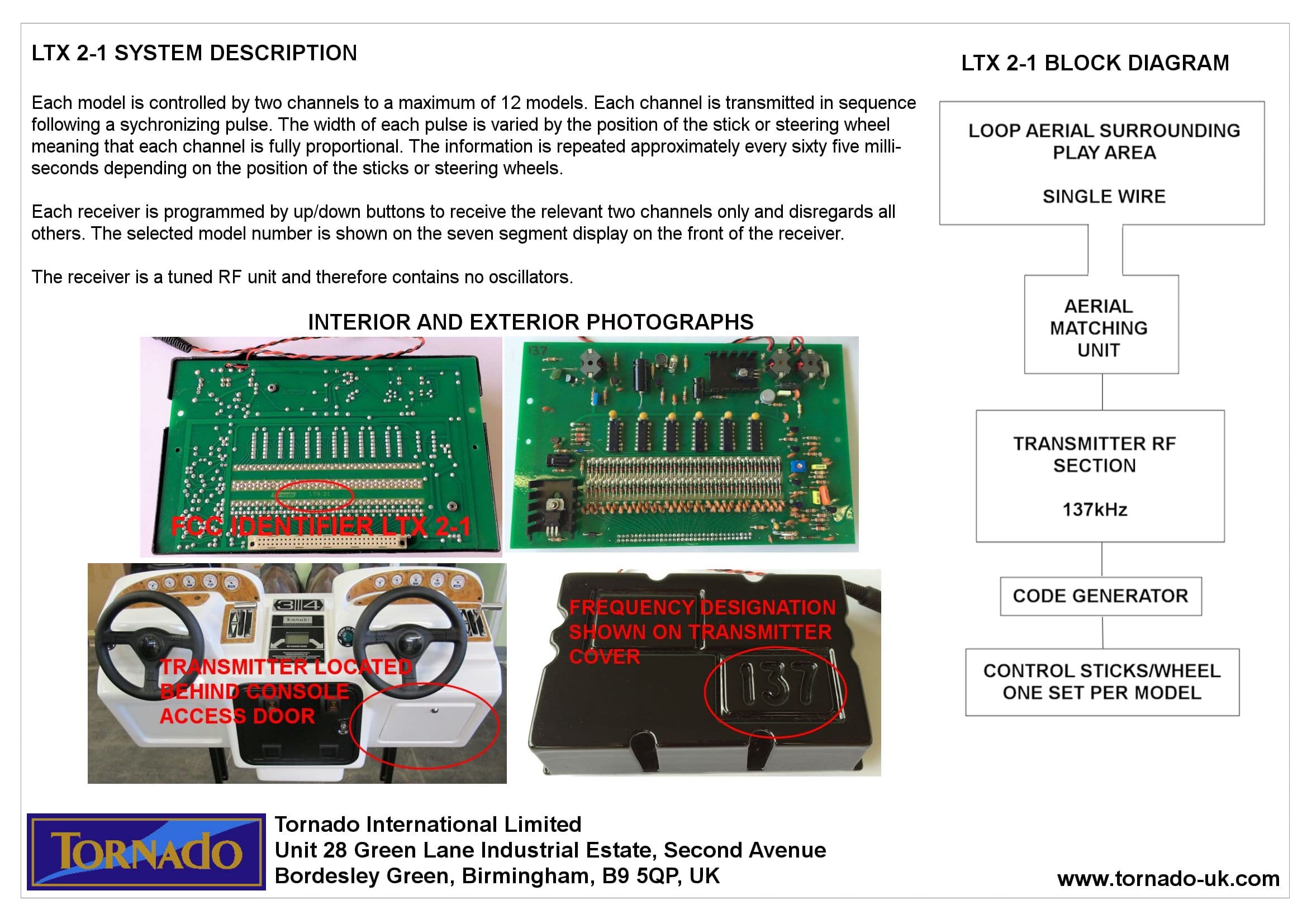
Click to zoom
Application Details
- Equipment Class
- DXX - Part 15 Low Power Communication Device Transmitter
- Date of Grant
- Apr 15, 1980
- Application Purpose
- Original Equipment
- Date of Application
- Oct 29, 1979
- Equipment Note
- Radio Control of Models at Amusement Arcades
- Frequency Range
- 0.13700000 - 0.13700000
- Country
- United Kingdom
Documents & Files
Document Text
Text extracted from the exhibit documents filed with the FCC. Open a document above to read the original.
Users Manual
1N00-510 Genesis 80cm Boat v1.1 02/04 ©Tornado International Ltd. 2003 -1- Confidential Genesis 80cm Boat 1N00-510 User Manual Note This unit is fitted with an updated (2013) design for console steering and forward/reverse. Please quote ‘OPTICAL’ set up when discussing parts or service. For parts, page 2 has substitutions for items 2 and 24. New part numbers to be advised shortly. Self Tuning Loop Output Board 1N00-510 Genesis 80cm Boat v1.1 02/04 ©Tornado International Ltd. 2003 -2- Confidential Your Serial Number is: Please quote this number when ordering parts or seeking telephone assistance. Company Information. Telephone Fax Technical Help +44(0)121-773-1827 (0)121-772-6056 Ask for Technical Help Parts & Accessories +44(0)121-773-1827 (0)121-772-6056 Ask for the Parts Dept Unit Sales +44(0)121-773-1827 (0)121-772-6056 Katie Roberts Comments: +44(0)121-773-1827 Stuart Bland Addresses: Head Office, Sales Office & Production Tornado International Ltd Unit 26 Green Lane Industrial Estate Second Avenue Birmingham B9 5QP England Tel: +44 (0)121-773-1827 Fax: +44 (0)121-772-6056 A Member of the Tornado International Leisure Group 1N00-510 Genesis 80cm Boat v1.1 02/04 ©Tornado International Ltd. 2003 -3- Confidential Conventions used in this Manual For clarity the following conventions are used in this manual: Paragraph Heading Meaning Tip! Information which will assist in the operation of the product Note! Information which is important for the correct operation of the product. Caution! Information which is VITAL to avoid injury to persons or damage to the product. Warning! Information which is VITAL to avoid serious injury to personnel or the public. Please take note of the information in shaded areas. If you have any questions with regard to the correct installation or operation of the product please contact Tornado International Ltd. Important – Please Read This! This manual is provided in good faith and is believed to be accurate. Because Tornado International have no control over the manner in which the product is used, users should satisfy themselves that any information or instruction contained in this manual is appropriate for the conditions under which the product is being installed and operated. In the interest of product development, Tornado International reserves the right to alter or modify the product as necessary. 1N00-510 Genesis 80cm Boat v1.1 02/04 ©Tornado International Ltd. 2003 -4- Confidential Introduction Thank you for purchasing this quality product from Tornado International Ltd. It will give you many years of trouble free service and if used in a suitable site will provide consistent profits. Please read and understand this manual before using the equipment. This manual contains the following sections. 1.00 Operating Procedures 1.01 Opening Instructions 1.02 Closing Instructions 2.00 Detail Overview of the System Here you will find detailed information about each part of the system with hints and cautions about the correct operation of the equipment. 3.00 Periodic Service Little is required in the way of periodic service. However time spent in following these procedures will pay dividends in improved reliability and service life. 1N00-510 Genesis 80cm Boat v1.1 02/04 ©Tornado International Ltd. 2003 -5- Confidential 1.00 Operating Procedures 1.01 Opening Instructions 1. Remove the console covers; visually check the consoles for any damage. 2. Turn the Power Supply on and check that the red lights are illuminated on each playing position. Note! The power supply must always be turned on before the batteries are connected to the models. 3. Check the charge meters on the battery chargers. The needle should be between 0 & 1 when the battery is fully charged. 4. Remove the batteries from the chargers and insert the spare batteries if they are not fully charged. 5. With the boat near to the operating area and keeping the boat propellers clear of any obstructions, carefully slide the battery into the boat. The propellers will rotate briefly. 6. Attach the boat top and lock it into position. Ensure it is the correct number for the receiver. 7. Carefully place the boat on the water inside the operating area. Caution! Place the boat on the water. Never launch or throw the boat onto the water, as this will cause the hull to fracture around the battery holder. 8. Repeat operations 5 to 7 for each model. 9. Coin and test each playing position in turn to ensure the console and boat operate correctly. The unit is now ready for use. 1.02 Closing Instructions 1. Trigger the playing position and drive the boat to the edge of the area and remove it from the water. 2. Place the boat on the stand supplied, remove the top and slide the battery out of the hull. 3. Inspect the propellers for damage or debris around the shaft. 4. Using polish and a cloth thoroughly clean the outside of the hull and top. 5. Place the boat vertically with the bows up in its storage position Caution! It is vital that the boat is stored vertically with the bows up to ensure that any water in the hull and water in the outer propeller shafts drains out of the rear. Storing the boat in any other position will allow water to enter the motors leading to their premature failure. 6. Repeat operations 1 to 4 for each model. 7. Turn off the Power Supply and check that all of the lights on the consoles are off. 8. Open the cash doors (remove the pad locks if fitted) and remove the cash. Note the coin counter readings. 1N00-510 Genesis 80cm Boat v1.1 02/04 ©Tornado International Ltd. 2003 -6- Confidential 9. Lock the cash doors and thoroughly clean and polish the consoles and playing positions. Place the covers over the consoles. 10. Place the used batteries in the charger. Check the charging meter readings. The needle should be between 2 and 10. 2.00 Detail Overview of the System 2.01 Consoles The consoles are made from glass fibre with a blockboard reinforcing for the back wall. Regular application of a quality proprie…
Text truncated - open the document above for the full version.
Users Manual
1N00-511 Genesis 80cm Boat Installation Manual - Export v1.0 08/03 ©Tornado International Ltd. 2003 -1- Confidential Genesis 80cm Boat 1N00-511 Installation Manual 1N00-511 Genesis 80cm Boat Installation Manual - Export v1.0 08/03 ©Tornado International Ltd. 2003 -2- Confidential Company Information. Telephone Fax Technical Help +44(0)121-773-1827 (0)121-772-6056 Ask for Technical Help Parts & Accessories +44(0)121-773-1827 (0)121-772-6056 Ask for the Parts Dept Unit Sales +44(0)121-773-1827 (0)121-772-6056 Katie Roberts Comments: +44(0)121-773-1827 Stuart Bland Addresses: Head Office, Sales Office & Production Tornado International Ltd Unit 28 Green Lane Industrial Estate Second Avenue Birmingham B9 5QP England Tel: +44(0)121-773-1827 Fax: +44(0)121-772-6056 A Member of the Tornado International Leisure Group 1N00-511 Genesis 80cm Boat Installation Manual - Export v1.0 08/03 ©Tornado International Ltd. 2003 -3- Confidential Conventions used in this Manual For clarity the following conventions are used in this manual: Paragraph Heading Meaning Tip! Information which will assist in the operation of the product Note! Information which is important for the correct operation of the product. Caution! Information which is VITAL to avoid injury to persons or damage to the product. Warning! Information which is VITAL to avoid serious injury to personnel or the public. Please take note of the information in shaded areas. If you have any questions with regard to the correct installation or operation of the product please contact Tornado International Ltd. Important – Please Read This! This manual is provided in good faith and is believed to be accurate. Because Tornado International have no control over the manner in which the product is used, users should satisfy themselves that any information or instruction contained in this manual is appropriate for the conditions under which the product is being installed and operated. In the interest of product development, Tornado International reserves the right to alter or modify the product as necessary. 1N00-511 Genesis 80cm Boat Installation Manual - Export v1.0 08/03 ©Tornado International Ltd. 2003 -4- Confidential On Delivery Before Opening Crates 1. Check the number of crates delivered agrees with the number on the shipping documents. 2. Inspect the crates for damage. If any damage is visible note the crate number, and the position and extent of the damage. If the crates are not to be opened immediately, the shipping company should be notified as soon as possible. If the crates are to be opened at this time, wait until the product is inspected for damage. 3. The crates should be moved to a position close to the operating area before opening. 4. The crates should be opened carefully, the contents removed and the quantities checked against the shipping notes. A product identification chart can be found at Appendix A. If any damage was noted on the outside of the crates, the product next to the damage should be inspected carefully. Any damage should be notified to the shipping company as soon as the product is unpacked. Any shortage should be notified to Tornado International Ltd. in writing (letter, fax or e-mail) as soon as possible and in any event not later than 5 days after receipt. 1N00-511 Genesis 80cm Boat Installation Manual - Export v1.0 08/03 ©Tornado International Ltd. 2003 -5- Confidential Before Installation All equipment (except UK) designed to operate off mains voltage supply (100v to 240v) is supplied without a connecting plug. Ensure that the required number of plugs are available before starting the installation. Caution! Check that the supply voltage matches the voltage setting on the front of the PSU and Charger cases. (Dia. 5 & 6) Tools & Items Required: (These are not supplied with the unit) Small flat screwdriver Medium flat screwdriver Medium cross point screwdriver Power drill 8mm drill bit 51mm hole cutter 10mm socket and ratchet ¼ whitworth socket (or adjustable spanner) Soldering Iron Staple Gun or 3mm cable clips 7mm cable clips 10off each coin/token used Setting Out the Equipment: 1. Before starting the installation place the consoles on the floor in the position they are to be mounted. The consoles may be mounted either indoors or outside. Console number “1” should be on the left with the consoles running in numerical order to the right. 2. Place the Power Supply Unit (PSU) in the position it will be used. The rear of the PSU has a large aluminium heat sink. It is important that the PSU is positioned so that there is an uninterrupted flow of cool air over the heat sink. Caution! The PSU must be mounted indoors and in such a position that the public do not have access to it. It must be protected from water. 3. Place the chargers in the position they will be used. The top and bottom of the charger case has vents to provide cooling. It is important that the chargers are positioned so that there is an uninterrupted flow of cool air over the vents. Caution! The chargers must be mounted indoors and in such a position that the public do not have access to them. They must be protected from water. 4. Check that the PSU and charger mains cables will reach the electric supply sockets. 5. Lay out the 24V PSU cable and check that it is long enough to reach from the master console to the PSU. 1N00-511 Genesis 80cm Boat Installation Manual - Export v1.0 08/03 ©Tornado International Ltd. 2003 -6- Confidential Note! The PSU cable must not be lengthened without consulting Tornado International Ltd. Tip! The master console can be identified by an additional door to the right of the coin acceptor door. It is usually number 4 or 6. It is the console with the transmitter inside. 6. If you have more than one console open the console door (the key is in the spares pack) and locate the console cable coiled up inside. Check that the cables from all additional consoles reach the console connection sockets inside the master console. When you have …
Text truncated - open the document above for the full version.
ID Label/Location Info
F.C.C. ID.: AMI gSY LTX 2-1 01217731827 TORNADO INTERNATIONAL LIMITED MADE tN ENGLAND lLoo-oo2 Thisdevicecomplieswith Part 15 of FCC Rules. Operation of this device is subject to the following two conditions:(1) This device may not cause harmful interference. (2) tnis device must accept any interference that may cause undesired operation. DATE OF MANUFACTURE. AND SERIAL NUMBER
Test Report
ERA TE,trI{NtrLtrEY R&D in electrical and eleclronic engineering Energy supply, utilisation and conservation Product design and prototype construclion Materials, systems and componeni testing Market research and lechnology transler MEASUREME}OIS OT EMISSTONS TROM TORN.qDO YIODEL PRODUCTS LTD LOOP TRANS}IITTER TYPE 2-1 ERA TEST REPORT NO SONNF3/L FEBRUARY 198c' Cleeve Road, Leatherhead, Surrey KT22 7SA. England Telephone: Leatherhead (03723) 74151 Telex: 264045 Purpose of Test : Approval Test Requested By : Tornado lr&cdel products r,td 52O Coventry Road, Small.Heath, . Birmlngham BlO OUN ENGLiTND ERA Test Report titc : Test, For : Test On : Company Order No : Test SpecifLcation : Equipnent SerLa1 No : Test Started : Test Completed : Fl.nal Test, Resu1t : so43/tr.3/L . Radlo frequency Emissions Tornado Model products toop Transmitter Tlpe 2_1 Subpart D para IS.IIL ECC Rules 13.2. 80 13. 2. Bo PASS I' Equipnent Manufacturer : rbrnado Model products Ltd al Report Wrltten By : Test Engineer : Supervisor : Manufactuerrs Repres I l.{r A.,1. Maddocks Mr T. Cooper &t l[eil/*/,r') ERII TEST REPoRT No 5o43l1F3/r FEBRUARY 1980 I'{EASIREI'{ENTS OF EMISSTONS FROM TORNADO I'{ODEIJ PRODUCTS LTD LOOP TRANSMITTER T)PE 2-I 1. I}ITRODUCTION The Tornado Model Products loop transmitter operating on 137 kHz has been examined to determine compJ-iance wittr Subpart D para t5.l1L of the FCC Rules relating to Low Power communication Devices operating at frequencieq below 15oo kHz. This folrows the originar series of tests carried out in september 1.979 which was reported on in ERA Test Report No 5o43/lx7/L. Further tests h/ere regarded as necessary and this present investigation was devised to satisfy a1r inquiries relating to the original measurements. According to the manufacturerrs informati-on, the loop sizes vary from small loops of 10 x I feet to the largest loop of about 5o feet diameter. The smaLlest loop is the onLy one which is likely to be elevated above ground. Several loop sizes and configurations have been measurements have been mad.e at various distances at selected points around, the loop. qramined and fieLd strength fron the Loop centre and In addition, measurements have been mad.e of harmonics and also of the dependance of the : voltage and tuning. 2. TEST I\4ETHoD Owing ao. *: presence of background lt was not possible to measure the the distribution of transmitter fundamentaL radiation on supply noise due to remote broadcast transmitters fundarnental radiation at 137 kHz at Measurements of r.f. raaiatiJn were made at the ERA open field test site at Leatherhead England. The measurements were made using a schwarzbeck FSI,IE r5I5 E.F. interference measuring receiver in conjunction with a Stoddart g22ao4 screened roop aerial; detaiLs of the measuring equipment are given in Appendix A. 2.L VarLation of field strensth vrith distarnse. ERA TEST REPORT NO 5O43III3/1 - 2 , FEBRUARY 1980 distances greater than 50 metres from the centre of the 1ooprand therefore a calcuLation of the field at 3OO metres was necessary. The rate of reduction of fietd intensity with increasing distance was therefore necessary in order to make an accuxate extrapalation to greater distances- To this endrmeasurements of fieLd intensity were mad.e at several distances from two different loop configrrrations-, a 10 x B foot loop and a 46 x 46 foot loop. The magnetic field intensity hras measured at 5 distances away from the former loop,and 7 distances away from the latter, sufficient to establish a uniform rate of decay. 2.2 Loop Ori.entation Measurements were made for the Io :< 8 foot J.oop both rvhen it vras laid on the ground, and when elevated to a horizontal plane 4 feet above the ' ground on a rotatabLe turntable. The fiel-d strength was monitored vrhilst the loop was rotated through 35Oo about a vertical axis. For the 46 x 46 foot loop measurements yere made at points 30 metres_ from thti centre of the loop,which were separated by angJ-es of 9oo and corresponded to East, North and west directions from the loop. 2.3 Loop gogfigurations rn addition to the square 46 x 46 foot Ioop, having approximatery the same area as a 50 foot diameter circle which is the }argest J-ikely to be encountered vrith this system, two other configurations of loop were tested. one comprised two loops of 23 x 46 feet, and the other three J-oops of 15 x 45 feet. For each configuration the transmitter vras trined to obtain maximum carrrent through the J-oop wiie. 2.4 Harmonic Emissions .. Measurements were made at 5 metres from the 1O x 8 foot J-oop of aL1 :the emissions from the loop which incLr:ded hamonic frequency emissions up to the 28th harmonic at 3.83 MHz. 2..5 Additional Tests Measurements were also made of the field intensity due to the 46 x 46 foot loop at the fundarnental frequency for the conditions when the transmitter tuning was adjusted to reduce the output current in the loop to about half of the resonant current. Measurements were also made of the field intensity when the supply voltage vras varieC over the range B5B to 1O4? of nominal. 3. RESULTS The measurements of magnetic field are expressed in terms of the equivalent plane wave electric fielC i.e volts/metre = amps,/metre x 377. The readings corresPond to the rms value of the sine wave required to obtaj-n the sarne resPonse on the indicator at the tuned frequency. For continuous wave signals, as we have in this case, the time constants at the detector and the meter play no partrand th.e response on the Schwarzbeck receiver is identical to that obtained with,an"averagert or ,,peak,, reading meter. 3.1 lance Figure I shows the dependance of field intensity wit} distances for the two loopsr 15 x B feet and 46 x 46 feet. The best line ttrrough both sets of points gives a dependance on distance of about d - 4-2, (g4dB down per decade of distance), tl.is where botlr loops are laid out on the ground. For a 100p in free space, i.f not near ground, we would, expect the rate of decav in t…
Text truncated - open the document above for the full version.
Test Report
ERA TEST REPORT NO 5O43l].F3lI I.EBRUARY 1980 APPEDIDIX.A (f) Specificatl,on of Schwarzbeck FSME 15t-5 Frequency range ; 8O kHz - 30 MHz Bandwidth : 9 kE;z Sensitivity : O.32 UV Inprt impedance : 50 ohms ' Attenuators : (a) r.f . ZO - IOO tn ldB steps (b) l.f. O - 2O ln LdB steps ' Rrlse reponse : QuasL peak; Ln accordance wittr CISPR publication No L Detector Tloe Constants : Chargeil m sec Dlsclraife3160 m sec (ff) Stoddart 922@-3 Screenedloop No of turns : I Loop diameter : 15 lnches i. ) Ranges : 8 ranges vLa switched transformer windings ERA TEST REPORT NO 5o43l1r3/1 FEBRUARY 1980 E{ 4 F{ o z H & H o o t-l rq s) HE1 E.g, E{ oEl ETE E-{ (o EO Hrn F{ o El fn sio aa F{o ro FI tf, \r o t- !i! o o ! +J o E a ra 6 * * fa r{ + o/) vl ril r- I rn ro l ld E{ (, z H & E-r a o F] Fl H f4 BI co @ r- r- tn r- N .r ff) \ol r- @ I I frl (n ro o) tn <r @ I (9 291 ^ HU(/) H2fi Ddd (,lE{E{ {(nEl HH5 oo a1 co o oa o (Y) o rf) z o H E{ H U' o o{ ri5 oc o'd o .ad H ru5 tn o -r{c sItn o ru'Q 6 d a o r.t ul c o rd c , o t{ Ul 4 o rld c t o S{ tl H o frl N H^ raH H cU frl tr{ Flv o{ ( ra to $ fn (f) (\l 6t tnrJ)tn Fl r{ rl o a rl o c ,i5 c t (u0 'O t{ dbt UJ4 oo O.d \A c0 'id q{ oo \0 o oo oc do) oo o {J t{ OO{ t{ oc BH t** (* "*t EI HI ERA TEST REPOR3 NO 5O43/IF3/1 n ' TABLE 2 .I'EBRUARY 1980 HABII{ONIC FREQTIE}rcY MEASUREMEIf,TS 10 x 8 Foot J.oop : on ground Measurement point 5 metres due West or- loop. TREQUENCY (tqll,z) HARMONIC ![UMBER qrELD rI{TENSITY dB (UVlmetre) REI,ATI\IE TO FUNDAITIEMTAT o.137 o.274 o.41I 1.23 2.o5 2.L9 2.88 3.15 3.42 3.83 I:. 2 3 9 15 L6 2L 23 25 28 116 64.5 43 33 29.5 32.5 31 32 32 29 o -51.5 -73 -83 i87.5 -83.5 -85 -84 -84 -87 ERA TEST REPORT NO 5O43,/1F3II. TABI,E 3 EI'FECT OT' DETUNTNG 46 x 45 foot loop : on ground : Measurement point 30 metre due West 6f loop. Freguency : L37 kHz. TEBRUARY 1980 TABLE 4 VARTATIOIS JN S:[,PPLY VOrgAgE 46 x 46 foot loop : on.ground Measurenent point 30 metre due West of loop TRANSMTT"ER METER E dB (Uv,/metre) t I t 83 88 83.s H @l (uvlmetre) IOOt Supply Voltage 85t Supply Vo!-tage 1048 Supply Voltage 88 88 88 ll l-i l li rl !; rl'l '-l-'f *r' [;i liill lljlt liiii lilir tr-1i 'l ! il il tr lrti, llrli lili llli ljijj rl+i ilii iil :r1l ;i l.l I li-: +i rrl ttiii tirii fiiil I# I:ili I f'1- iii; rlri ii;i t;;' il+1 lril rl il 'fil !1l j rri; i! 1: ttr "ri] 11i1 ' !'l' rlti il,il ll,ir lll,, lii;l Liiil lilrt llir fflti ii'ri li-1 lt'j; t,ri; iii+i t,.:i I I il.: l],ii :.1 *I +r ri i I -il ;li l:r It ti ii :l rii iil ,lri 'l:i iiti !rll tlil ;r,i 'lrl iii, - i'l .j"1 I i; iU, ;il i ,,,., :r'i i ii:l i';; * ill iil iii l:ri fi,i lrli Ffrirffi ffi i:i l r-l+i ;ril r.it: 1i, I til i l:l1 [. .; lili *ii rlli ii Lr ii Iiln iiI+I iii ni rli, :f-: i... rir o c _r t+l+ li: i fti l+* H+i t rif *-l' tl !-t rrl i i1 l.i illt +ri r+ t+ rff iu] ttr i-i H !i! ill !+,.1 iH +i :i1 i -ri1 _l+t :ff i:lr +tt i+;+ , i1. l1l ':1 !i rj riri i f-l : +-+ :!* I lllr h r':: t'i+: l--rt l:iii ,ri .iil il ! I ., ?+ ..11 :ir r11 :r n +.li Jii !lll iil I ,rli iii l; li: l:r!- lii,l t::: '.li rl.:: j; r'; :: t: ;;I -r:.:: +1' t: F Ii l- i+i; sit '-i i l-. l::i ii; -+l :tl { .r ii t 5i1 i111 f i..q ;;i: L7 li t: l::i l'l i1 :T:I r.l,j !-! ii ii 't_r I i '+11 iiri h-:: I-'_' I::il *J t-r-: t::!l l-t.l i=i I i!:: ti! ril ;-i: !.11 ";.l i i.ti +-! i i+.1 t-' . [j:: i1:r t1!r . r] r'-.i l-::i ti.! Ir+r i F_f!. ri-li itl t: a t.;;. i! ttr ia' i;:1 +:i :-:-1i H i1 l.: ja: E:li tsq: lif rl l,lil [[1 ,iil ilil tt r! iil, li.l I Ijir lilr n i. h j'l i.!r i ,,] r-i: i-i+l it:: l;lty lii'l-- iti; t LL.I; lrrri triit "lrl l: ir,, I --r I r ir,' lliri l?Tri li:q ttIl lrirl li i,+1 :llli .!l . lt iLl ilil llt, i+l +1- l. lrl. iirl 1.1 i', +i+ 1-ii '1ii j+i1 i]'t-i -i;rl 'ir 1lt1 1!l-l iii! 11 lj 'i ? r'l ,1,' i-,:+ li-ri ,ti: ,iii rltT i.1r-i r i-i J' i iri t'1r +1 J-i. I I J. i t 1 !i +.i ;;-i+ ii: ,r-li r!ii -iiii iii ll, - fii !l-i !i! /rli lili 11 1i jirL ri! , ll :il ii I ii lii iri rj ii: tjl + tll t, ,t r i'1 l,+i rit.l Itl:r Ir: t:i :fi r:tl lJ-i lr:.i t'++; ,I ; i...1 ilil -iar I :y' /-.'; -'ll l .,L.1 .-hi l!' I .ji rril t'i rij j :;! rrg illl /ti :+ti i,il iIt lr I -+il .irl ,1- 'i ti . l+1. I I 'i{l -el ::tj .:iil A :rii -:.i.i r+r I -i+l I -l-l-r I til I 'it if1 f, .-1 r ]tr; -:i I t1' .,l i .r: i t:li i i;, r'1 ii i.i i-i l- !l i1 l1' rl ti rl ? i1 [: ltil :-! r i*i :: +-li ilj ii: +.l l lf' .ii r1'l ii: :il '!r-' ;111 .t,r i1 ii ft:1 lrl.l lr! r.: l1 F r-l :!.:r -''.l :ir' f..rr i-+.- i:t-i lll,- .r' ,1 I ll: .i]: rj+' . lta '-'t Y.:. :'i_ ' /* -,. i :11 r r.l 'ir i1 ! s.i rlli ':1 1: li j"'? t' rilr il 1-.ir+ ;i i"H r-1 ul r -+i ri ;1 ii lr : i.' iil --_l Z:: .:i I i'i H i r.l irt fi ij il :.t. .,] .irt ;;;l 1.rt ii li 7 fr Z, '::vt l:l :it *{ rri; ;J .l z ri il i:i ii ;i 1 v ::-'I ;i9 :ri .'+ I i- / '* r'l :rill :.IF ir i:i.i :iil r-i / /"i rr1_ll 'lirl ,lrll lli'l :..-, I rliil 1 rrf,] :iili i--:: I 't;ll ,ritl ilil ir iil iir it. ilt I.ri' r irl lit J rllil :1 !tl ll llt ir:l ,.tl , ,i.i i ,rllt :r:l +: iii rir 'ir i tl +i ir ll ii il +l ll. ::rl i:) t,;l r't-j L;1 ii rl r.-l I I !-.1 -ri: /. ": f , ! ,,11 i:: i .!r; . luii rlrl iII jrifl :rl ll A ,;:ll !i i.l ilr! ,!ilt llirl ,+iLi tli, '/in i.rl iitii :ltl n,i "irl ilin rtiil i: i r-i i -i.i l llrl.l !I i1i il .T I il ;i il iit , itrj ii;l li,l ,tt irrl 'lt iif : ::- t -:l; iiil I ti: - iL- iiii iii i qi :lfi ii:.i I ilil 'i1 ii lr 'i ttll liiri :r"i i , i-ti ri! ;iil ir -l i.j.ir l ;,1 i ii, i:i' ,iit ;]li 'il t ii :i :t 1r .ii-i ii:r ':' lli i:l I r"f irt: -:.! itii i': i f- ii r;ii :rl . ll :: l"l :j .-l iti 1:i lrl !!t i;r :i1 l': r:1 tn I ftl 1+1 | ri :. t-it: .+. i i.j :i r1 -tt- 'l ti ij ii i::r i'l !.1- 1:' ii --!ll i,i,t i,-:l t l.il i::.11 : -t'l 1-:l t i iiii 1t ilii ' +ri r l-rj rIl.: Pli til; ir!i -t i+ uli l-rj i':r i:il itit lir ii: ::l Li+ iil ijl t -il j-i.. ti !:l 1;. rl i!' r.l iir Itl ;riI l .;.1 l_i 1_r1 i;li Hi I Ilt ijx I I :i, rr1 il, lr .t u J ii /,; i'1 ++l l- I:I #:l 1t rt 't1i lirr .t ;lll ;…
Text truncated - open the document above for the full version.
Test Setup Photos
ERA TE,trI{NtrLtrEY R&D in electrical and eleclronic engineering Energy supply, utilisation and conservation Product design and prototype construclion Materials, systems and componeni testing Market research and lechnology transler MEASUREME}OIS OT EMISSTONS TROM TORN.qDO YIODEL PRODUCTS LTD LOOP TRANS}IITTER TYPE 2-1 ERA TEST REPORT NO SONNF3/L FEBRUARY 198c' Cleeve Road, Leatherhead, Surrey KT22 7SA. England Telephone: Leatherhead (03723) 74151 Telex: 264045 Purpose of Test : Approval Test Requested By : Tornado lr&cdel products r,td 52O Coventry Road, Small.Heath, . Birmlngham BlO OUN ENGLiTND ERA Test Report titc : Test, For : Test On : Company Order No : Test SpecifLcation : Equipnent SerLa1 No : Test Started : Test Completed : Fl.nal Test, Resu1t : so43/tr.3/L . Radlo frequency Emissions Tornado Model products toop Transmitter Tlpe 2_1 Subpart D para IS.IIL ECC Rules 13.2. 80 13. 2. Bo PASS I' Equipnent Manufacturer : rbrnado Model products Ltd al Report Wrltten By : Test Engineer : Supervisor : Manufactuerrs Repres I l.{r A.,1. Maddocks Mr T. Cooper &t l[eil/*/,r') ERII TEST REPoRT No 5o43l1F3/r FEBRUARY 1980 I'{EASIREI'{ENTS OF EMISSTONS FROM TORNADO I'{ODEIJ PRODUCTS LTD LOOP TRANSMITTER T)PE 2-I 1. I}ITRODUCTION The Tornado Model Products loop transmitter operating on 137 kHz has been examined to determine compJ-iance wittr Subpart D para t5.l1L of the FCC Rules relating to Low Power communication Devices operating at frequencieq below 15oo kHz. This folrows the originar series of tests carried out in september 1.979 which was reported on in ERA Test Report No 5o43/lx7/L. Further tests h/ere regarded as necessary and this present investigation was devised to satisfy a1r inquiries relating to the original measurements. According to the manufacturerrs informati-on, the loop sizes vary from small loops of 10 x I feet to the largest loop of about 5o feet diameter. The smaLlest loop is the onLy one which is likely to be elevated above ground. Several loop sizes and configurations have been measurements have been mad.e at various distances at selected points around, the loop. qramined and fieLd strength fron the Loop centre and In addition, measurements have been mad.e of harmonics and also of the dependance of the : voltage and tuning. 2. TEST I\4ETHoD Owing ao. *: presence of background lt was not possible to measure the the distribution of transmitter fundamentaL radiation on supply noise due to remote broadcast transmitters fundarnental radiation at 137 kHz at Measurements of r.f. raaiatiJn were made at the ERA open field test site at Leatherhead England. The measurements were made using a schwarzbeck FSI,IE r5I5 E.F. interference measuring receiver in conjunction with a Stoddart g22ao4 screened roop aerial; detaiLs of the measuring equipment are given in Appendix A. 2.L VarLation of field strensth vrith distarnse. ERA TEST REPORT NO 5O43III3/1 - 2 , FEBRUARY 1980 distances greater than 50 metres from the centre of the 1ooprand therefore a calcuLation of the field at 3OO metres was necessary. The rate of reduction of fietd intensity with increasing distance was therefore necessary in order to make an accuxate extrapalation to greater distances- To this endrmeasurements of fieLd intensity were mad.e at several distances from two different loop configrrrations-, a 10 x B foot loop and a 46 x 46 foot loop. The magnetic field intensity hras measured at 5 distances away from the former loop,and 7 distances away from the latter, sufficient to establish a uniform rate of decay. 2.2 Loop Ori.entation Measurements were made for the Io :< 8 foot J.oop both rvhen it vras laid on the ground, and when elevated to a horizontal plane 4 feet above the ' ground on a rotatabLe turntable. The fiel-d strength was monitored vrhilst the loop was rotated through 35Oo about a vertical axis. For the 46 x 46 foot loop measurements yere made at points 30 metres_ from thti centre of the loop,which were separated by angJ-es of 9oo and corresponded to East, North and west directions from the loop. 2.3 Loop gogfigurations rn addition to the square 46 x 46 foot Ioop, having approximatery the same area as a 50 foot diameter circle which is the }argest J-ikely to be encountered vrith this system, two other configurations of loop were tested. one comprised two loops of 23 x 46 feet, and the other three J-oops of 15 x 45 feet. For each configuration the transmitter vras trined to obtain maximum carrrent through the J-oop wiie. 2.4 Harmonic Emissions .. Measurements were made at 5 metres from the 1O x 8 foot J-oop of aL1 :the emissions from the loop which incLr:ded hamonic frequency emissions up to the 28th harmonic at 3.83 MHz. 2..5 Additional Tests Measurements were also made of the field intensity due to the 46 x 46 foot loop at the fundarnental frequency for the conditions when the transmitter tuning was adjusted to reduce the output current in the loop to about half of the resonant current. Measurements were also made of the field intensity when the supply voltage vras varieC over the range B5B to 1O4? of nominal. 3. RESULTS The measurements of magnetic field are expressed in terms of the equivalent plane wave electric fielC i.e volts/metre = amps,/metre x 377. The readings corresPond to the rms value of the sine wave required to obtaj-n the sarne resPonse on the indicator at the tuned frequency. For continuous wave signals, as we have in this case, the time constants at the detector and the meter play no partrand th.e response on the Schwarzbeck receiver is identical to that obtained with,an"averagert or ,,peak,, reading meter. 3.1 lance …
Text truncated - open the document above for the full version.
Contact Information
Applicant
Stuart Bland(Managing Director)
Technical Contact
Tornado International LtdPhilip Mackenzie
[email protected]011441217731827
Unit 28 Green Lane Industrial Estate · Birmingham · United Kingdom
Non-Technical Contact
Tornado International LtdSteve Roberts
[email protected]011441217731827
Test Firm
Federal Communication Commission (FCC USE ONLY)George Tannahill
[email protected]301-362-3026
Technical Specifications
| # | Rule Parts | Frequency Range | Power Output |
|---|---|---|---|
| 1 | 15.111 | 0.137 MHz - 0.137 MHz | - |