APIBDS277Blu-RAY DISC SYSTEM
Harman International Industries, Inc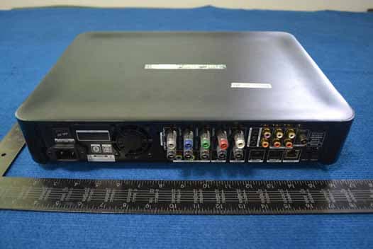
Click to zoom
Application Details
- Equipment Class
- DTS - Digital Transmission System
- Date of Grant
- Sep 05, 2012
- Application Purpose
- Original Equipment
- Date of Application
- Sep 02, 2012
- Equipment Note
- Blu-RAY DISC SYSTEM
- Frequency Range
- 2412.00000000 - 2462.00000000
- Country
- United States
Documents & Files
Document Text
Text extracted from the exhibit documents filed with the FCC. Open a document above to read the original.
Users Manual
Quick-Start Guide Audio/video receiver BDS 275/BDS 277/BDS 575/BDS 577 FPO BDS X75 BDS 2 Introduction and Connections Thank you for choosing a Harman Kardon ® product! This quick-start guide contains all the information you need to connect and set up your new BDS Blu-ray Disc ™ receiver. To conserve our natural resources, your BDS receiver does not include a printed owner’s manual. An owner’s manual containing complete information about operating all of your new Blu-ray Disc receiver’s features is available at our Web site. Go to www. harmankardon.com and download the BDS Blu-ray Disc Receiver Owner’s Manual. Your BDS receiver is designed to be compatible with region management information that is encoded on most Blu-ray Disc recordings and DVD recordings. Your receiver will only play discs that contain region coding for the area where your receiver was shipped and intended for sale: Area Where SoldBlu-ray Disc Region Code DVD Region Code USA, Canada Europe, Middle East Korea, S.E. Asia Mexico, Latin America Australia, New Zeland Russia, India China For example, BDS receivers shipped to and sold in the USA will only play Blu-ray Discs that contain region code A and DVD discs that contain region code 1. Connections Connect the Satellite Speakers CAUTION: Before making any connections to the BDS receiver, ensure that the receiver’s AC cord is unplugged from the receiver and the AC outlet. Making speaker connections with the receiver plugged in and turned on could damage your speakers. Speakers and receivers have corresponding (+) and (–) connection terminals. BDS 275/BDS 277 whiteleft channel (+) redright channel (+) black(–) on both channels BDS 575/BDS 577 whitefront left (+) redfront right (+) bluesurround left (+) graysurround right (+) greencenter (+) black(–) on all channels Most speakers use red to denote the (+) terminal and black for the (–) terminal. Be sure to connect each speaker identically: (+) on the speaker to (+) on the receiver and (–) on the speaker to (–) on the receiver. Miswiring one or more speakers results in thin sound, weak bass and a poor stereo image. Front Right Speaker Front Left Speaker BDS Receiver (BDS 575 shown) Center Speaker* Surround Right Speaker* * Used only with BDS 575/BDS 577 receiver Surround Left Speaker* IMPORTANT: Make sure the (+) and (–) bare wires do not touch each other or the other terminal. Touching wires can cause a short circuit that can damage the receiver. 3 BDS English Connections Connect the Subwoofer IMPORTANT: Do not plug the subwoofer’s AC power cord into an AC outlet at this time. Mono RCA Audio Cable (not supplied) Powered Subwoofer Connect the Radio Antenna FM Antenna Connect a TV or Video Display TV HDMI ® Cable (supplied) NOTE: If your TV supports the HDMI Audio Return Channel and you have HDMI devices (such as an Internet connection) already connected directly to your TV, you can feed their sound to the BDS receiver via the HDMI Monitor Out connector’s Audio Return Channel, and they will not require additional connections to the receiver. Connect to Your Home Network To Internet Network Modem Cat. 5/5E Connecting Your HDMI ® Source Devices HDMI-Equipped Source Device To HDMI Output HDMI Cable (not supplied) BDS 4 Connections Connecting Your Component Video Source Device Component Video-Equipped Source Device* To Component Video Outputs To Analog Audio Outputs Component Video Cable (not supplied) Stereo Audio Cable (not supplied) Connecting Your Optical Digital Audio Source Devices Optical Digital-Equipped Source Device Remove Caps To Optical Digital Audio Output Optical Digital Audio Cable (not supplied) Connecting Your Coaxial Digital Audio Source Device Coaxial Digital-Equipped Source Device To Coaxial Digital Audio Output Coaxial Digital Audio Cable (not supplied) Connecting Your Analog Audio Source Devices To Stereo Analog Audio Output Stereo Audio Cable (not supplied) Analog Source Device 5 BDS English Connections and Receiver Setup Connect the AC Power 110V – 240V, 50Hz/60Hz Receiver Set Up the Receiver Install the Batteries in the Remote Control 1.2.3. Turn On the Receiver Set the receiver’s Main Power switch in the “On” position. Receiver Main Power Switch To set up your BDS receiver you will use the remote to navigate through the on-screen menus and to make selections from them. OK PROGRAMBOOKMARKTHUMBNAILZOOM TOP MENUSURROUND VOL VOL POP-UP DISPLAY POWERTV DISC HDMI 1HDMI 2HDMI 3 COMP USB AUXRADIO EJECT APPLE CHCH Home Button OK Button Cursor Controls Back Button • Use the Cursor Up/Down buttons to navigate through the menu list. When an item is highlighted, a blue border will appear around it. • To select a highlighted item, press the OK button. The screen will change depending on your selection. • To return to the previous screen, press the Back button. BDS 6 Setup Wizard and Configuring the Receiver Setup Wizard When you turn your BDS receiver on for the first time, the on-screen menu will display the Setup Wizard. Setup Wizard Welcome to the Harman Kardon BDS Setup Wizard. Some simple information is needed to ensure you get the best experience from your product. You can adjust these settings later in addition to making changes to more advanced settings by selecting ‘Settings’ from the Home Menu. Page 1/5 Next OK Before you can use your BDS system you need to set the language and make a few basic settings so that the BDS receiver’s video output will work properly with your TV. Press the OK button, and the Wizard’s language screen will appear. Setup Wizard Please select which language you would like the BDS menus to appear in. Page 2/5 Next Previous OK After setting the language you want the on-screen menus to appear in, press the OK button, and the Wizard’s TV resolution screen will appear. Setup Wizard Please select the highest resolution that your TV supports. If you are unsure, select ‘Auto’. Upon making a selection the screen will be changed to the chosen resolution. You will be presented with the resolutio…
Text truncated - open the document above for the full version.
Cover Letter(s)
Harman International Industries, Inc. 8500 Balboa Blvd, Nothridge, CA 91329 UNITED STATES 022311 – 6 Authority to Act as Agent Date: _Aug 6, 2012_ ___ American Certification Body, Inc. 6731 Whittier Avenue Suite C110 McLean, VA 22101 To Whom It May Concern: __ GUANGZHOU GRG METROLOGY&TEST CO.,LTD.__ is authorized to act on our behalf, until otherwise notified, for applications to American Certification Body, Inc. (ACB). We certify that we are not subject to denial of federal benefits, that includes FCC benefits, pursuant to Section 5301 of the Anti-Drug Abuse Act of 1988, 21 U.S.C. 862. Further, no party, as defined in 47 CFR 1.2002 (b), to the application is subject to denial of federal benefits, that includes FCC benefits. Thank you, Agency Agreement Expiration Date: ____9 Months___ By: _______________________ __ Fernando Reyes____ ____ (Signature 1 ) (Print name) Title: ___Director, Global Quality___ On behalf of: ___ Harman International Industries, Inc.____ (Company Name) Telephone: ___+1-818-895-8173_____ ______ 1 - Must be signed by applicant contact given for applicant on the FCC site, or by the authorized agent if an appropriate authorized agent letter has been provided. Letters should be placed on appropriate letterhead.
Cover Letter(s)
Harman International Industries, Inc. 8500 Balboa Blvd, Nothridge, CA 91329 UNITED STATES 022311 – 6 Request for Confidentiality Date: _ July 1, 2012____ Subject: Confidentiality Request for: __ __APIBDS277___ Pursuant to FCC 47 CRF 0.457(d) and 0.459 and IC RSP-100, Section 10, the applicant requests that a part of the subject FCC application be held confidential. Type of Confidentiality Requested Exhibit Short Term √ Permanent Block Diagrams √ Short Term Permanent External Photos √ Short Term Permanent* 2 Internal Photos Short Term √ Permanent Operation Description/Theory of Operation Short Term √ Permanent Parts List & Placement/BOM Short Term Permanent Tune-Up Procedure Short Term √ Permanent Schematics √ Short Term Permanent Test Setup Photos √ Short Term Permanent* User’s Manual *Note: ______(Insert Explanation as Necessary)______ __ Harman International Industries, Inc.__ has spent substantial effort in developing this product and it is one of the first of its kind in industry. Having the subject information easily available to "competition" would negate the advantage they have achieved by developing this product. Not protecting the details of the design will result in financial hardship. Permanent Confidentiality: The applicant requests the exhibits listed above as permanently confidential be permanently withheld from public review due to materials that contain trade secrets and proprietary information not customarily released to the public. Short-Term Confidentiality: The applicant requests the exhibits selected above as short term confidential be withheld from public view for a period of __45_ _ days from the date of the Grant of Equipment Authorization and prior to marketing. This is to avoid premature release of sensitive information prior to marketing or release of the product to the public. Applicant is also aware that they are responsible to notify ACB in the event information regarding the product or the product is made available to the public. ACB will then release the documents listed above for public disclosure pursuant to FCC Public Notice DA 04-1705. NOTE for Industry Canada Applications: The applicant understands that until such time that IC distinguishes between Short Term and Permanent Confidentiality, either type of marked exhibit above will simply be marked Confidential when submitted to IC. Sincerely, By: __________________________ ____ Fernando Reyes_____ (Signature/Title 3 ) (Print name) 2 - The asterisked items (*) require further justification before permanent confidentiality will be allowed. These also currently require review by the FCC under their Permit-But-Ask policy before the grant is issued and can delay completion of an application. Further justification should be added to the note above. One such example for a potted device would be: “The EUT is FULLY potted using a non-removable epoxy based material. Removal of potting material causes irreparable damage to internal circuitry. See photographs exhibits that outline the device before and after potting.” 3 - Must be signed by applicant contact given for applicant on the FCC site, or by the authorized agent if an appropriate
External Photos
EXTERNAL PHOTOS
ID Label/Location Info
Label on bottom device Label on back device
Internal Photos
Bluetooth Modular Bluetooth Modular Bluetooth Modular WIFI Modular WIFI Modular
RF Exposure Info
RF Exposure Compliance Requirement 1. Standard requirement 15.247(b)(4) requirement: (4) The conducted output power limit specified in paragraph (b) of this section is based on the use of antennas with directional gains that do not exceed 6 dBi. Except as shown in paragraph (c) of this section. if transmitting antennas of directional gain greater than 6 dBi are used. the conducted output power from the intentional radiator shall be reduced below the stated values in paragraphs (b)(1). (b)(2). and (b)(3) of this section. as appropriate. by the amount in dB that the directional gain of the antenna exceeds 6 dBi. TCB Exclusion List (7 July 2002) Exposure category low threshold high threshold general population (60/fGHz) mW. d < 2.5 cm (120/fGHz) mW. d ≥ 2.5 cm (900/fGHz) mW. d < 20 cm occupational (375/fGHz) mW. d < 2.5 cm (900/fGHz) mW. d ≥ 2.5 cm (2250/fGHz) mW. d < 20 cm When d>20cm,the EUT should mark the recommend use distance for EUT external antenna and the MPE=1mW/cm 2 . 2. EUT RF Exposure The Max Conducted Peak Output Power is 16.71 dBm(46.88mW) in channel 6; The best case gain of the antenna is 3.0dBi. 3.0dB logarithmic terms convert to numeric result is nearly 2.0 According to the formula. calculate the EIRP test result: EIRP= P x G = 46.88 mW x 2.0 = 93.76mW S=1mW/cm 2 So , R= S PG 4 = 1000014.34 0.246.88 = 2.73cm So the recommend use distance for EUT external antenna is larger than 2.73 centimeter.
Test Report
Page 1 of 122 TEST REPORT Report No.: EM201200311-6 Application No.: ZJ00016980 Applicant: Harman International Industries, Incorporated Applicant Address: 8500 Balboa Blvd, Northridge, CA 91329, UNITED STATES Sample Description: Blu-RAY DISC SYSTEM Model: BDS 277 Adding Model Test Location: Guangzhou GRG Metrology and Test Co., Ltd Test Specification: FCC Part 15,Subpart C:2010 Test Date: 2012-06-21 to 2012-07-20 Issue Date: 2012-07-23 Test Result: Pass. Prepared By: Reviewed By: Approved By: Eddy Zong/ Test Engineer Jane Cao / Technical Support Gavin Wu / Manager Date: 2012-07-23 Date: 2012-07-23 Date: 2012-07-23 Other Aspects: Abbreviations: ok / P = passed; fail / F = failed; n.a. / N = not applicable The test result in this test report refers exclusively to the presented test sample. This report shall not be reproduced except in full, without the written approval of GRGT. GRG Metrology and Test Co., Ltd. Address: 163, Pingyun Road, West of Huangpu Avenue, Guangzhou, Guangdong, P.R. China Tel:+86-20-38699960 Fax:+86-20-38695185 Email: [email protected] http://www.grgtest.com Ver.:2.0/ 01. Jan. 2012 Report No.: EM201200311-6 Application No.: ZJ00016980 Page 2 of 122 FCC ID: APIBDS277 DIRECTIONS OF TEST 1. This station carries out test task according to the national regulation of verifications which can be traced to National Primary Standards and BIPM. 2. The test report merely corresponds to the test sample. It is not permitted to copy extracts of these test result without the written permission of the test laboratory. 3. If there is any objection concerning the test, the client should inform the laboratory within 15 days from the date of receiving the test report. Report No.: EM201200311-6 Application No.: ZJ00016980 Page 3 of 122 FCC ID: APIBDS277 Table of Contents 1. TEST RESULT SUMMARY ............................................................................................................................................... 4 2. GENERAL DESCRIPTION OF EUT................................................................................................................................. 5 2.1 APPLICANT .................................................................................................................................................................... 5 2.2 MANUFACTURER ......................................................................................................................................................... 5 2.3 BASIC DESCRIPTION OF EQUIPMENT UNDER TEST ............................................................................................. 5 2.4 DESCRIPTION OF SUPPORT UNITS ........................................................................................................................... 5 3. LABORATORY AND ACCREDITATIONS ..................................................................................................................... 6 3.1 LABORATORY ............................................................................................................................................................... 6 3.2 ACCREDITATIONS ....................................................................................................................................................... 6 3.3 MEASUREMENT UNCERTAINTY ............................................................................................................................... 6 3.4 LIST OF USED TEST EQUIPMENT AT GRGT ............................................................................................................. 7 4. TEST RESULT ..................................................................................................................................................................... 8 4.1 ANTENNA REQUIREMENT ......................................................................................................................................... 8 4.2 CONDUCTED EMISSION MEASUREMENT ............................................................................................................... 9 4.2.1 LIMITS ...................................................................................................................................................................... 9 4.2.2 TEST PROCEDURES ............................................................................................................................................... 9 4.2.3 TEST SETUP .......................................................................................................................................................... 10 4.2.4 TEST RESULTS ...................................................................................................................................................... 11 4.3 RADIATED ELECTROMAGNETIC DISTURBANCE ............................................................................................... 13 4.3.1 LIMITS .................................................................................................................................................................... 13 4.3.2 TEST PROCEDURES ............................................................................................................................................. 13 4.3.3 TEST SETUP .......................................................................................................................................................... 14 4.3.4 TEST RESULTS ...................................................................................................................................................... 16 4.4 SPURIOUS EMISSIONS AT ANTENNA PORT .......................................................................................................... 40 4.4.1 LIMITS .................................................................................................................................................................... 40 4.4.2 TEST PROCEDURES ..............…
Text truncated - open the document above for the full version.
Test Setup Photos
TEST SETUP PHOTOS
Contact Information
Applicant
Terry Shi(Prin.Engineer,Regulatory Compliance, Quality)
Technical Contact
GUANGZHOU GRG METROLOGY&TEST CO.,LTD.Angel Liu
[email protected]86-20-39699960
163 Ping Yun Rd,West of HuangPu Ave, · Guangzhou, · China
Test Firm
Guangzhou GRG Metrology And Test Technology LTD.Huang Yingling
Technical Specifications
| # | Rule Parts | Frequency Range | Power Output |
|---|---|---|---|
| 1 | 15C | 2.41 GHz - 2.46 GHz | 47.00 mW |
Other Applications from Harman International Industries, Inc
APITUNEBEAM3
Jul 30, 2026BLUETOOTH HEADSET
Equipment Class
DTS - Digital Transmission SystemAPITUNEBUDS3
Jul 30, 2026BLUETOOTH HEADSET
Equipment Class
DSS - Part 15 Spread Spectrum TransmitterAPITUNEFLEX3
Jul 29, 2026BLUETOOTH HEADSET
Equipment Class
DTS - Digital Transmission SystemAPIJBLVBUDS3
Jul 21, 2026BLUETOOTH HEADSET
Equipment Class
DTS - Digital Transmission SystemAPIJBLGO5H
Jul 21, 2026PORTABLE BLUETOOTH SPEAKER
Equipment Class
DSS - Part 15 Spread Spectrum Transmitter