APIJBLGTR102Car amplifier
Harman International Industries, Inc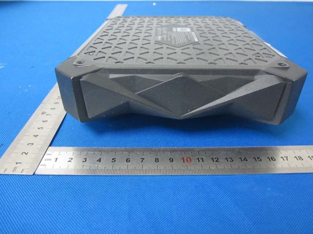
Click to zoom
Application Details
- Equipment Class
- DSS - Part 15 Spread Spectrum Transmitter
- Date of Grant
- Sep 28, 2015
- Application Purpose
- Original Equipment
- Date of Application
- Sep 28, 2015
- Equipment Note
- Car amplifier
- Frequency Range
- 2402.00000000 - 2480.00000000
- Country
- United States
Documents & Files
Document Text
Text extracted from the exhibit documents filed with the FCC. Open a document above to read the original.
Users Manual
JBL GTR-7535/104/102 Amplifier Quick- Connect Guide MOUNTING IMPORTANT: Disconnect the vehicle’s negative (–) battery terminal before beginning the installation. Select a location that provides enough air for the amp to cool itself. • Do not mount the amplifier outside the car or in the engine compartment. SPEAKER CONNECTIONS Always connect the (+) speaker terminal on the amplifier to the (+) terminal on the speaker and the (–) speaker terminal on the amplifier to the (–) terminal on the speaker. IMPORTANT: Make sure the (+) and (–) bare wires do not touch each other or the other terminal at either the amplifier terminals or the speaker terminals. Touching wires can cause a short circuit that can damage the amplifier. GTR-7535/104 4-Channel Operation • Minimum impedance for each speaker is 2 ohms. IMPORTANT: This quick-connect guide contains information about mounting and connecting your amplifier. For complete installation, connection, setup and adjustment information, download the full GTR-7535/GTR-104/GTR-102 Amplifier User Manual at jbl.com. IMPORTANT: Disconnect the vehicle’s negative (–) battery terminal before beginning the installation. Using the Power and Speaker Connectors GROUND & POWER CONNECTIONS GTR-7535/104/102 • Use sandpaper to clear the paint from the metal surface at the ground connection. Use a star-type lock washer to secure the connection. • Install a fuse holder for a 90A fuse (GTR-7535), 60A fuse (GTR-104) or 30A fuse (GTR-102) on the power (12V) wire within 18" (46cm) of the (+) battery terminal. Do not install the fuse in the holder at this time. In place of a fuse, you can install a circuit breaker of equivalent amperage rating. Power Connectors GTR-7535GTR-104/ GTR-102 Audio System Head Unit Chassis Ground (bare metal) 18” (46cm) Fuse: GTR-7535 = 90A GTR-104 = 60A GTR-102 = 30A Remote Turn-On (optional) >#18AWG (0.82mm 2 )Wire >#10AWG (5.26mm 2 )Wire >#10AWG (5.26mm 2 )Wire Front Left Speaker Rear Left Speaker Rear Right Speaker Front Right Speaker EN HARMAN International Industries, Incorporated 8500 Balboa Boulevard, Northridge, CA 91329 USA www.jbl.com © 2015 HARMAN International Industries, Incorporated. All rights reserved. JBL is a trademark of HARMAN International Industries, Incorporated, registered in the United States and/or other countries. All Rights Reserved. Features, specifications and appearance are subject to change without notice. INPUT CONNECTIONS Connect the source unit’s RCA line outputs to the amplifier's left and right inputs, as shown in the illustration below. CONTROL PANEL CONNECTION Connect the supplied control panel to the amplifier’s Controller connector, as shown in the illustration below. The control panel includes a long cable and a mounting flange, allowing it to be mounted in a convenient location in the vehicle’s cabin. For complete control panel mounting instructions, please download the full GTR-7535/GTR-104/GTR-102 Amplifier User Manual at jbl.com. SETTING THE CONTROLS AND USING THE AMPLIFIER For complete information about setting the amplifier’s controls and using all of the amplifier’s features, please download the full GTR-7535/GTR-104/GTR-102 Amplifier User Manual at jbl.com. If your source unit does not have RCA outputs use the supplied bare wire-to-RCA adapters to connect the source unit’s speaker wires to the amplifier, as shown in the illustration below. When you’re finished connecting the source unit’s speaker outputs to the adapters, plug the adapters into the amplifier’s input connectors as shown in the previous illustrations. GTR-7535/104 2-Channel Bridged Operation • Minimum impedance for each speaker is 4 ohms. GTR-102 2-Channel Operation • Minimum impedance for each speaker is 2 ohms. GTR-102 1-Channel Bridged Operation • Minimum speaker impedance is 4 ohms. Left Speaker Right Speaker NOTE: For additional speaker connection diagrams, download the full GTR-7535/GTR-104/GTR-102 Amplifier User Manual at jbl.com. Source Unit Rear RCA Line Outputs Front RCA Line Outputs • For bridged operation, use a Y”-adapter to connect the source unit’s left and right outputs to the amplifier’s front and rear left and right channel input connector(s) as shown in the illustration below. Left Speaker Right Speaker Subwoofer FR Amplificateur JBL GTR-7535/104/102 Guide de branchement rapide MONTAGE IMPORTANT : débranchez la borne négative de la batterie (-) du véhicule avant de commencer l'installation. Sélectionnez un emplacement qui fournit assez d'air pour que l'amplificateur se refroidisse par lui-même. • Ne montez pas l'amplificateur à l'extérieur de la voiture ou dans le compartiment moteur. BRANCHEMENTS DES HAUT-PARLEURS Branchez toujours la borne (+) du haut-parleur sur l'amplificateur à la borne (+) du haut-parleur et la borne (-) du haut-parleur sur l'amplificateur à la borne (-) du haut-parleur. IMPORTANT : veillez à ce que les fils nus (+) et (-) ne se touchent pas et ne touchent pas d'autre borne au niveau des bornes d'amplificateur et de haut-parleur. Un contact des fils peut créer un court-circuit et endommager l'amplificateur. Utilisation des 4 canaux du GTR-7535/104 • L'impédance minimale de chaque haut-parleur est 2 ohms. IMPORTANT : ce guide de branchement rapide contient des informations sur le montage et le branchement de votre amplificateur. Pour des informations détaillées sur l'installation, le branchement, la configuration et les réglages, téléchargez le mode d'emploi complet de l'amplificateur GTR-7535/GTR-104/GTR-102 sur jbl.com. IMPORTANT : débranchez la borne négative de la batterie (-) du véhicule avant de commencer l'installation. Utilisation des connecteurs d'alimentation et de haut-parleur CONNEXIONS DE MASSE ET D'ALIMENTATION GTR-7535/104/102 • Poncez au papier abrasif pour enlever la peinture de la surface métallique à l'emplacement de la connexion à la masse. Utilisez une rondelle de blocage en étoile pour bloquer la connexion. • Installez un porte-fusible pour un fusible de 90 A (GTR-7535), 60 …
Text truncated - open the document above for the full version.
Users Manual
RSS standard(s). This device complies with Industry Canada's licence-exempt RSSs. Le présent appareil est conforme aux CNR d'Industrie Canada applicables aux appareils radio exempts de licence. L'exploitation est autorisée aux deux conditions suivantes : (1) l'appareil ne doit pas produire de brouillage, et (2) l'utilisateur de l'appareil doit accepter tout brouillage radioélectrique subi, même si le brouillage est susceptible d'en compromettre le fonctionnement. AVERTISSEMENT : Ne pas ingérer BATTERIE, BURN RISQUE CHIMIQUE [La télécommande fournie avec] Ce produit contient une pile pièce / bouton. Si la pile pièce / bouton est avalé, il peut causer des brûlures internes graves en seulement 2 heures et peut conduire à la mort. Gardez piles neuves et usagées de portée des enfants. Si vous pensez que les batteries pourraient avoir été avalé ou placé à l'intérieur d'une partie du corps, consulter immédiatement un médecin.
Cover Letter(s)
Harman International Industries, Incorporated 8500 Balboa Boulevard, Northridge, CA 91329 USA Declaration of difference Date: 2015-9-6 Federal Communications Commission To Whom It May Concern: The product: Car amplifier, Model No.: GTR-102 and K2, the two models have the same Antenna shape, circuit diagram and RF module, but only difference on appearance, color, trade name and model No.. Yours sincerely, Signatory Name Tim Song Position Compliance Manager Company Name Harman International Industries, Incorporated Address 8500 Balboa Blvd, Northridge, CA 91329, UNITED STATES Tel / Fax +86-755-8668 2338/+86-755-8636 0599 E-Mail [email protected] The product: Car amplifier, Model No.: GTR-102 and K2, the two models are electrically identical, but only appearance, color, trade name and model No. are different.
External Photos
Dongguan Dongdian Testing Service Co., Ltd Report No.: DDT-R15Q0807-2E2 Page 51 of 61 14. Photos of the EUT Dongguan Dongdian Testing Service Co., Ltd Report No.: DDT-R15Q0807-2E2 Page 52 of 61 Dongguan Dongdian Testing Service Co., Ltd Report No.: DDT-R15Q0807-2E2 Page 53 of 61 Dongguan Dongdian Testing Service Co., Ltd Report No.: DDT-R15Q0807-2E2 Page 54 of 61
Internal Photos
Dongguan Dongdian Testing Service Co., Ltd Report No.: DDT-R15Q0807-2E2 Page 55 of 61 Dongguan Dongdian Testing Service Co., Ltd Report No.: DDT-R15Q0807-2E2 Page 56 of 61 Dongguan Dongdian Testing Service Co., Ltd Report No.: DDT-R15Q0807-2E2 Page 57 of 61 Dongguan Dongdian Testing Service Co., Ltd Report No.: DDT-R15Q0807-2E2 Page 58 of 61 Dongguan Dongdian Testing Service Co., Ltd Report No.: DDT-R15Q0807-2E2 Page 59 of 61 Dongguan Dongdian Testing Service Co., Ltd Report No.: DDT-R15Q0807-2E2 Page 60 of 61 Dongguan Dongdian Testing Service Co., Ltd Report No.: DDT-R15Q0807-2E2 Page 61 of 61 END OF REPORT
RF Exposure Info
RF Exposure evaluation According to KDB 447498 D01 General RF Exposure Guidance v05 The 1-g and 10-g SAR test exclusion thresholds for 100 MHz to 6 GHz at test separation distances ≤ 50 mm are determined by: [(max. power of channel, including tune-up tolerance, mW)/(min. test separation distance, mm)] ·[√f(GHz)] ≤ 3.0 for 1-g SAR and ≤ 7.5 for 10-g extremity SAR, where f(GHz) is the RF channel transmit frequency in GHz Power and distance are rounded to the nearest mW and mm before calculation The result is rounded to one decimal place for comparison Worse case is as below: [2402 MHz 1.86dBm(1.53 mW) output power] (1.53 mW /5mm) ·[√2.402 (GHz)]= 0.5 <3.0 for 1-g SAR Then SAR evaluation is not required
Test Report
Dongguan Dongdian Testing Service Co., Ltd Report No.: DDT-R15Q0807-2E2 Page 1 of 49 FCC AND IC CERTIFICATION TEST REPORT FOR Issued By: Dongguan Dongdian Testing Service Co., Ltd. Add: No. 17, Zongbu Road 2, Songshan Lake Sci&Tech, Industry Park, Dongguan City, Guangdong Province, China, 523808 Tel: +86-0769-22891499 Http://www.dgddt.com Applicant : Harman International Industries, Incorporated Address : 8500 Balboa Boulevard, Northridge, CA 91329, UNITED STATES Equipment under Test : Car amplifier Model No : GTR-102, K2 Trade Mark : JBL/Infinity FCC ID : APIJBLGTR102 IC : 6132A-JBLGTR102 Manufacturer : Harman International Industries, Incorporated Address : 8500 Balboa Boulevard, Northridge, CA 91329, UNITED STATES Report No.: DDT-R15Q0807-2E2 Issued Date: Aug. 20, 2015 Dongguan Dongdian Testing Service Co., Ltd Report No.: DDT-R15Q0807-2E2 Page 2 of 49 TABLE OF CONTENTS Test report declares......................................................................................................................4 1. Summary of test results ............................................................................................................... 5 2. General test information .............................................................................................................. 6 2.1. Description of EUT ..................................................................................................................... 6 2.2. Accessories of EUT ..................................................................................................................... 6 2.3. Assistant equipment used for test ................................................................................................ 6 2.4. Block diagram of EUT configuration for test ............................................................................. 6 2.5. Test environment conditions ....................................................................................................... 7 2.6. Deviations of test standard .......................................................................................................... 7 2.7. Test laboratory ............................................................................................................................. 7 2.8. Measurement uncertainty ............................................................................................................ 8 3. Maximum Peak Output Power .................................................................................................... 8 3.1. Test equipment ............................................................................................................................ 8 3.2. Block diagram of test setup ......................................................................................................... 8 3.3. Limits .......................................................................................................................................... 9 3.4. Test Procedure ............................................................................................................................. 9 3.5. Test Result ................................................................................................................................... 9 4. 20dB Bandwidth and 99% Bandwidth ...................................................................................... 10 4.1. Test equipment .......................................................................................................................... 10 4.2. Block diagram of test setup ....................................................................................................... 10 4.3. Limits ........................................................................................................................................ 10 4.4. Test Procedure ........................................................................................................................... 10 4.5. Test Result ................................................................................................................................. 11 4.6. Original test data ....................................................................................................................... 11 5. Carrier Frequency Separation .................................................................................................... 18 5.1. Test equipment .......................................................................................................................... 18 5.2. Block diagram of test setup ....................................................................................................... 18 5.3. Limits ........................................................................................................................................ 18 5.4. Test Procedure ........................................................................................................................... 18 5.5. Test Result ................................................................................................................................. 18 5.6. Original test data ....................................................................................................................... 19 6. Number Of Hopping Channel ................................................................................................... 20 6.1. Test equipment .......................................................................................................................... 20 6.2. Block diagram of test setup ....................................................................................................... 20 6.3. Limits ........................................................................................................................................ 20 6.4. Test Procedure ...............................................................................…
Text truncated - open the document above for the full version.
Test Setup Photos
Dongguan Dongdian Testing Service Co., Ltd Report No.: DDT-R15Q0807-2E2 Page 50 of 61 13. Test setup photograph
Contact Information
Applicant
Terry Shi(Prin.Engineer,Regulatory Compliance, Quality)
Test Firm
Dongguan Dongdian Testing Service Co.,LtdJamy Yu
[email protected]086-0769-22891499
Technical Specifications
| # | Rule Parts | Frequency Range | Power Output |
|---|---|---|---|
| 1 | 15C | 2.40 GHz - 2.48 GHz | 1.53 mW |
Other Applications from Harman International Industries, Inc
APITUNEBEAM3
Jul 30, 2026BLUETOOTH HEADSET
Equipment Class
DTS - Digital Transmission SystemAPITUNEBUDS3
Jul 30, 2026BLUETOOTH HEADSET
Equipment Class
DSS - Part 15 Spread Spectrum TransmitterAPITUNEFLEX3
Jul 29, 2026BLUETOOTH HEADSET
Equipment Class
DTS - Digital Transmission SystemAPIJBLVBUDS3
Jul 21, 2026BLUETOOTH HEADSET
Equipment Class
DTS - Digital Transmission SystemAPIJBLGO5H
Jul 21, 2026PORTABLE BLUETOOTH SPEAKER
Equipment Class
DSS - Part 15 Spread Spectrum Transmitter