APISB26CTCSoundbar Speaker System
Harman International Industries, Inc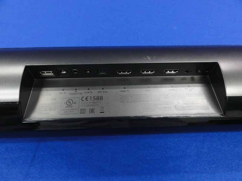
Click to zoom
Application Details
- Equipment Class
- DXX - Part 15 Low Power Communication Device Transmitter
- Date of Grant
- Jul 24, 2013
- Application Purpose
- Original Equipment
- Date of Application
- Jul 22, 2013
- Equipment Note
- Soundbar Speaker System
- Frequency Range
- 2403.35000000 - 2477.35000000
- Country
- United States
Documents & Files
Document Text
Text extracted from the exhibit documents filed with the FCC. Open a document above to read the original.
Users Manual
1 1 1 2 3 748 4 5 6 7 55 1234567891110 6 8 3 2 4 5 7 Slide slots in Soundbar feet onto tabs on brackets AC Power Cord 0.5s SB26SUB CROSSOVER PAIRING POWER MIN MAX PHASE 7 For All Products: 1. Read these instructions. 2. Keep these instructions. 3. Heed all warnings. 4. Follow all instructions. 5. Do not use this apparatus near water. 6. Clean only with a dry cloth. 7. Do not block any ventilation openings. Install this apparatus in accordance with the manufacturer’s instructions. 8. Do not install this apparatus near any heat sources such as radiators, heat registers, stoves or other apparatus (including amplifiers) that produce heat. 9. Do not defeat the safety purpose of the polarized or grounding-type plug. A polarized plug has two blades with one wider than the other. A grounding-type plug has two blades and a third grounding prong. The wide blade or the third prong is provided for your safety. If the provided plug does not fit into your outlet, consult an electrician for replacement of the obsolete outlet. 10. Protect the power cord from being walked on or pinched, particularly at plugs, convenience receptacles and the point where they exit from the apparatus. 11. Use only attachments/accessories specified by the manufacturer. 12. Use only with the cart, stand, tripod, bracket or table specified by the manufacturer or sold with the apparatus. When a cart is used, use caution when moving the cart/apparatus combination to avoid injury from tip-over. 13. Unplug this apparatus during lightning storms or when unused for long periods of time. 14. Refer all servicing to qualified service personnel. Servicing is required when the apparatus has been damaged in any way, such as when the power-supply cord or plug is damaged, liquid has been spilled or objects have fallen into the apparatus, or the apparatus has been exposed to rain or moisture, does not operate normally or has been dropped. 15. Do not expose this apparatus to dripping or splashing, and ensure that no objects filled with liquids, such as vases, are placed on the apparatus. 16. To disconnect this apparatus from the AC mains completely, disconnect the power- supply cord plug from the AC receptacle. 17. The mains plug of the power-supply cord shall remain readily operable. 18. Do not expose batteries to excessive heat such as sunshine, fire or the like. RISK OF ELECTRIC SHOCK. DO NOT OPEN. THE LIGHTNING FLASH WITH AN ARROWHEAD SYMBOL, WITHIN AN EQUILATERAL TRIANGLE, IS INTENDED TO ALERT THE USER TO THE PRESENCE OF UNINSULATED “DANGEROUS VOLTAGE” WITHIN THE PRODUCT’S ENCLOSURE THAT MAY BE OF SUFFICIENT MAGNITUDE TO CONSTITUTE A RISK OF ELECTRIC SHOCK TO PERSONS. THE EXCLAMATION POINT WITHIN AN EQUILATERAL TRIANGLE IS INTENDED TO ALERT THE USER TO THE PRESENCE OF IMPORTANT OPERATING AND MAINTENANCE (SERVICING) INSTRUCTIONS IN THE LITERATURE ACCOMPANYING THE PRODUCT. WARNING: TO REDUCE THE RISK OF FIRE OR ELECTRIC SHOCK, DO NOT EXPOSE THIS APPARATUS TO RAIN OR MOISTURE. CAUTION FCC AND IC STATEMENT FOR USERS (USA AND CANADA ONLY) This device complies with part 15 of the FCC Rules. Op- eration is subject to the following two conditions: (1) This device may not cause harmful interference, and (2) this device must accept any interference received, including interference that may cause undesired operation. This Class B digital apparatus complies with Canadian ICES-003. Cet appareil numérique de la classe B est conforme à la norme NMB-003 du Canada. Federal Communication Commis- sion Interference Statement This equipment has been tested and found to comply with the limits for a Class B digital device, pursuant to Part 15 of the FCC Rules. These limits are designed to pro- vide reasonable protection against harmful interference in a residential installation. This equipment generates, uses and can radiate radio frequency energy and, if not installed and used in accordance with the instructions, may cause harmful interference to radio communications. However, there is no guarantee that interference will not occur in a particular installation. If this equipment does cause harmful interference to radio or television recep- tion, which can be determined by turning the equipment off and on, the user is encouraged to try to correct the interference by one or more of the following measures: • Reorient or relocate the receiving antenna. • Increase the separation between the equipment and receiver. • Connect the equipment into an outlet on a circuit differ- ent from that to which the receiver is connected. • Consult the dealer or an experienced radio/TV techni- cian for help. Caution: Changes or modifications not expressly ap- proved by HARMAN could void the user’s authority to op- erate the equipment. For Products That Transmit RF Energy: FCC AND IC INFORMATION FOR USERS This device complies with Part 15 of the FCC rules and Industry Canada license-exempt RSS 210. Operation is subject to the following two conditions: (1) This device may not cause harmful interference; and (2) this device must accept any interference received, including interfer- ence that may cause undesired operation. FCC/IC Radiation Exposure Statement This equipment complies with FCC/IC RSS-102 radiation exposure limits set forth for an uncontrolled environ- ment. This equipment should be installed and operated with minimum distance 20cm between the radiator & your body. For Products with Radio Re- ceivers That Can Use an Ex- ternal Antenna (USA ONLY): CATV (Cable TV) or Antenna Grounding If an outside antenna or cable system is connected to this product, be certain that it is grounded so as to pro- vide some protection against voltage surges and static charges. Section 810 of the National Electrical Code (NEC), ANSI/NFPA No. 70-1984, provides information with respect to proper grounding of the mast and supporting structure, grounding of the lead-in wire to an antenna dis- charge unit, size of grounding conductors, location of an- tenna discharge unit, connection to grounding el…
Text truncated - open the document above for the full version.
External Photos
R AUDIX Technology (Shenzhen) Co., Ltd. FCC ID:APISB26CTC page Audix Technology (Shenzhen) Co., Ltd. Report No. ACS-F13115 14-1 14. PHOTOS OF THE EUT Figure 1 General Appearance of the EUT Figure 2 General Appearance of the EUT R AUDIX Technology (Shenzhen) Co., Ltd. FCC ID:APISB26CTC page Audix Technology (Shenzhen) Co., Ltd. Report No. ACS-F13115 14-2 Figure 3 General Appearance of the EUT Figure 4 General Appearance of the EUT
ID Label/Location Info
Model: SB26 CNTR
Internal Photos
R AUDIX Technology (Shenzhen) Co., Ltd. FCC ID:APISB26CTC page Audix Technology (Shenzhen) Co., Ltd. Report No. ACS-F13115 14-3 Figure 5 Inside of the EUT Figure 6 Inside of the EUT R AUDIX Technology (Shenzhen) Co., Ltd. FCC ID:APISB26CTC page Audix Technology (Shenzhen) Co., Ltd. Report No. ACS-F13115 14-4 Figure 7 Inside of the EUT Figure 8 Inside of the EUT R AUDIX Technology (Shenzhen) Co., Ltd. FCC ID:APISB26CTC page Audix Technology (Shenzhen) Co., Ltd. Report No. ACS-F13115 14-5 Figure 9 Components Side of the PCB Figure 10 Components Side of the PCB R AUDIX Technology (Shenzhen) Co., Ltd. FCC ID:APISB26CTC page Audix Technology (Shenzhen) Co., Ltd. Report No. ACS-F13115 14-6 Figure 11 Components Side of the PCB Figure 12 Components Side of the PCB R AUDIX Technology (Shenzhen) Co., Ltd. FCC ID:APISB26CTC page Audix Technology (Shenzhen) Co., Ltd. Report No. ACS-F13115 14-7 Figure 13 Components Side of the PCB Figure 14 Components Side of the PCB R AUDIX Technology (Shenzhen) Co., Ltd. FCC ID:APISB26CTC page Audix Technology (Shenzhen) Co., Ltd. Report No. ACS-F13115 14-8 Figure 15 Components Side of the PCB Figure 16 Components Side of the PCB R AUDIX Technology (Shenzhen) Co., Ltd. FCC ID:APISB26CTC page Audix Technology (Shenzhen) Co., Ltd. Report No. ACS-F13115 14-9 Figure 17 Components Side of the PCB R AUDIX Technology (Shenzhen) Co., Ltd. FCC ID:APISB26CTC page Audix Technology (Shenzhen) Co., Ltd. Report No. ACS-F13115 14-10 Figure 18 Components Side of the PCB R AUDIX Technology (Shenzhen) Co., Ltd. FCC ID:APISB26CTC page Audix Technology (Shenzhen) Co., Ltd. Report No. ACS-F13115 14-11 Figure 19 Components Side of the PCB R AUDIX Technology (Shenzhen) Co., Ltd. FCC ID:APISB26CTC page Audix Technology (Shenzhen) Co., Ltd. Report No. ACS-F13115 14-12 Figure 20 Components Side of the PCB R AUDIX Technology (Shenzhen) Co., Ltd. FCC ID:APISB26CTC page Audix Technology (Shenzhen) Co., Ltd. Report No. ACS-F13115 14-13 Figure 21 Components Side of the PCB R AUDIX Technology (Shenzhen) Co., Ltd. FCC ID:APISB26CTC page Audix Technology (Shenzhen) Co., Ltd. Report No. ACS-F13115 14-14 Figure 22 Components Side of the PCB R AUDIX Technology (Shenzhen) Co., Ltd. FCC ID:APISB26CTC page Audix Technology (Shenzhen) Co., Ltd. Report No. ACS-F13115 14-15 Figure 23 Components Side of the PCB R AUDIX Technology (Shenzhen) Co., Ltd. FCC ID:APISB26CTC page Audix Technology (Shenzhen) Co., Ltd. Report No. ACS-F13115 14-16 Figure 24 Components Side of the PCB R AUDIX Technology (Shenzhen) Co., Ltd. FCC ID:APISB26CTC page Audix Technology (Shenzhen) Co., Ltd. Report No. ACS-F13115 14-17 Figure 25 Components Side of the PCB Figure 26 Components Side of the PCB R AUDIX Technology (Shenzhen) Co., Ltd. FCC ID:APISB26CTC page Audix Technology (Shenzhen) Co., Ltd. Report No. ACS-F13115 14-18 Figure 27 Components Side of the PCB Figure 28 Components Side of the PCB R AUDIX Technology (Shenzhen) Co., Ltd. FCC ID:APISB26CTC page Audix Technology (Shenzhen) Co., Ltd. Report No. ACS-F13115 14-19 Figure 29 Components Side of the PCB Figure 30 Speaker R AUDIX Technology (Shenzhen) Co., Ltd. FCC ID:APISB26CTC page Audix Technology (Shenzhen) Co., Ltd. Report No. ACS-F13115 14-20 Figure 31 Speaker Figure 32 Power Adapter R AUDIX Technology (Shenzhen) Co., Ltd. FCC ID:APISB26CTC page Audix Technology (Shenzhen) Co., Ltd. Report No. ACS-F13115 14-21 Figure 33 Power Adapter Figure 34 Power Adapter R AUDIX Technology (Shenzhen) Co., Ltd. FCC ID:APISB26CTC page Audix Technology (Shenzhen) Co., Ltd. Report No. ACS-F13115 14-22 Figure 35 Remote Controller Figure 36 Remote Controller
Test Report
R AUDIX Technology (Shenzhen) Co., Ltd. FCC ID:APISB26CTC Audix Technology (Shenzhen) Co., Ltd. Report No. ACS-F13167 FCC PART 15C TEST REPORT FOR CERTIFICATION On Behalf of Harman International Industries, Incorporated System Name : Soundbar Speaker System System Model Number : SB26 EUT Name : Soundbar Brand Name Model No. Harman SB26 CNTR FCC ID: APISB26CTC Prepared for : Harman International Industries, Incorporated 8500 Balboa Blvd, Northridge, CA 91329, UNITED STATES Prepared By : Audix Technology (Shenzhen) Co., Ltd. No. 6, Ke Feng Rd., 52 Block, Shenzhen Science & Industrial Park, Nantou, Shenzhen, Guangdong, China Tel: (0755) 26639496 Report Number : ACS-F13167 Date of Test : Jun.20~24, 2013 Date of Report : Jul.09, 2013 R AUDIX Technology (Shenzhen) Co., Ltd. FCC ID:APISB26CTC Audix Technology (Shenzhen) Co., Ltd. Report No. ACS-F13167 TABLE OF CONTENTS Description Page 1. SUMMARY OF STANDARDS AND RESULTS ......................................................... 1-1 1.1. Description of Standards and Results................................................................................... 1-1 2. GENERAL INFORMATION ......................................................................................... 2-1 2.1. Description of Device (EUT) ............................................................................................... 2-1 2.2. Special Test information ...................................................................................................... 2-2 2.3. Channel List ......................................................................................................................... 2-2 2.4. Tested Supporting System Details ....................................................................................... 2-3 2.5. Block Diagram of Test Setup ............................................................................................... 2-3 2.6. Test Facility.......................................................................................................................... 2-4 2.7. Measurement Uncertainty (95% confidence levels, k=2) .................................................... 2-4 3. POWER LINE CONDUCTED EMISSION MEASUREMENT ................................. 3-1 3.1. Test Equipment .................................................................................................................... 3-1 3.2. Block Diagram of Test Setup ............................................................................................... 3-1 3.3. Power Line Conducted Emission Test Limits ...................................................................... 3-1 3.4. Configuration of EUT on Test ............................................................................................. 3-1 3.5. Operating Condition of EUT................................................................................................ 3-2 3.6. Test Procedure...................................................................................................................... 3-2 3.7. Conducted Emission at Mains Terminals Test Results ........................................................ 3-2 4. RADIATED EMISSION MEASUREMENT ................................................................ 4-1 4.1. Test Equipment .................................................................................................................... 4-1 4.2. Block Diagram of Test Setup ............................................................................................... 4-1 4.3. Radiated Emission Limit Standard: FCC 15.209 ................................................................. 4-2 4.4. EUT Configuration on Test.................................................................................................. 4-2 4.5. Operating Condition of EUT................................................................................................ 4-3 4.6. Test Procedure...................................................................................................................... 4-3 4.7. Radiated Emission Test Results ........................................................................................... 4-3 5. 20DB BANDWIDTH TEST ............................................................................................ 5-1 5.1. Test Equipment .................................................................................................................... 5-1 5.2. Limit ..................................................................................................................................... 5-1 5.3. Test Results .......................................................................................................................... 5-1 6. BAND EDGE COMPLIANCE TEST............................................................................ 6-1 6.1. Test Equipment .................................................................................................................... 6-1 6.2. Limit ..................................................................................................................................... 6-1 6.3. Test Produce ......................................................................................................................... 6-1 6.4. Test Results .......................................................................................................................... 6-1 7. DEVIATION TO TEST SPECIFICATIONS ............................................................... 7-1 8. PHOTOGRAPH OF TEST............................................................................................. 8-1 8.1. Photos of Conducted Disturbance at Mains Terminals Test ................................................ 8-1 8.2. Photos of Radiated Emission Test (30-1000MHz)............................................................... 8-2 9. PHOTOS OF THE EUT .......................................................................…
Text truncated - open the document above for the full version.
Test Setup Photos
R AUDIX Technology (Shenzhen) Co., Ltd. FCC ID:APISB26CTC page Audix Technology (Shenzhen) Co., Ltd. Report No. ACS-F13115 13-1 13. PHOTOGRAPH OF TEST 13.1. Photos of Conducted Disturbance at Mains Terminals Test R AUDIX Technology (Shenzhen) Co., Ltd. FCC ID:APISB26CTC page Audix Technology (Shenzhen) Co., Ltd. Report No. ACS-F13115 13-2 13.2. Photos of Radiated Emission Test (30-1000MHz) R AUDIX Technology (Shenzhen) Co., Ltd. FCC ID:APISB26CTC page Audix Technology (Shenzhen) Co., Ltd. Report No. ACS-F13115 13-3 (Above 1000MHz)
Contact Information
Applicant
Terry Shi(Prin.Engineer,Regulatory Compliance, Quality)
Technical Contact
AUDIX Technology (Shenzhen) Co., Ltd.
[email protected]86-755-26639497
52 Block Shenzhen Science&Industry · Shenzhen · China
Non-Technical Contact
AUDIX Technology (Shenzhen) Co., Ltd.
[email protected]86-755-26639497
Test Firm
Audix Technology (Shenzhen) Co., Ltd.Smart Tsai
Technical Specifications
| # | Rule Parts | Frequency Range | Power Output |
|---|---|---|---|
| 1 | 15C | 2.40 GHz - 2.48 GHz | - |
Other Applications from Harman International Industries, Inc
APITUNEBEAM3
Jul 30, 2026BLUETOOTH HEADSET
Equipment Class
DTS - Digital Transmission SystemAPITUNEBUDS3
Jul 30, 2026BLUETOOTH HEADSET
Equipment Class
DSS - Part 15 Spread Spectrum TransmitterAPITUNEFLEX3
Jul 29, 2026BLUETOOTH HEADSET
Equipment Class
DTS - Digital Transmission SystemAPIJBLVBUDS3
Jul 21, 2026BLUETOOTH HEADSET
Equipment Class
DTS - Digital Transmission SystemAPIJBLGO5H
Jul 21, 2026PORTABLE BLUETOOTH SPEAKER
Equipment Class
DSS - Part 15 Spread Spectrum Transmitter