AQE-AD511AD511 Iridium Active Antenna
Applied Satellite Technology LTD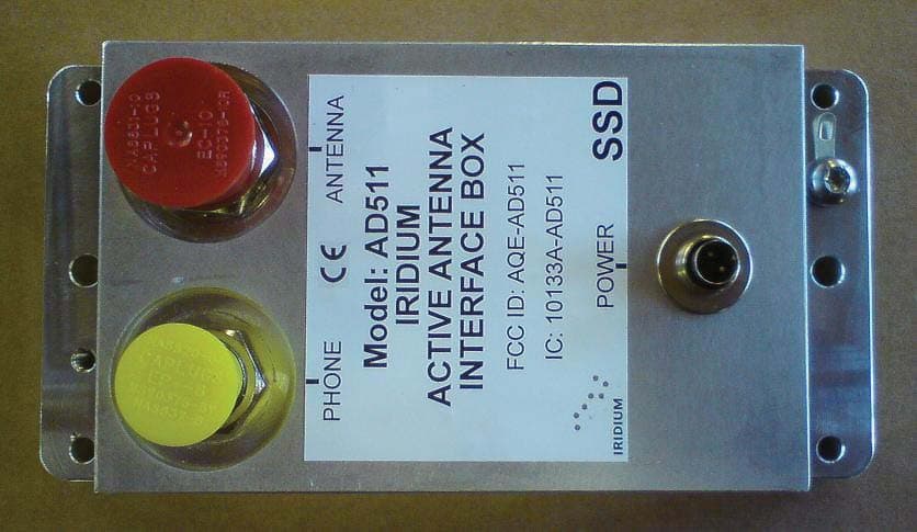
Click to zoom
Application Details
- Equipment Class
- AMP - Amplifier
- Date of Grant
- Aug 08, 2013
- Application Purpose
- Original Equipment
- Date of Application
- Aug 08, 2013
- Equipment Note
- AD511 Iridium Active Antenna
- Frequency Range
- 1616.00000000 - 1626.50000000
- Country
- United Kingdom
Documents & Files
Document Text
Text extracted from the exhibit documents filed with the FCC. Open a document above to read the original.
Users Manual
AD511 Active Iridium Antenna User Manual June 2013 AD511 Active Iridium Transmitter/Receiver Antenna with up to 160 metres of coaxial down-lead and DC Power Break-In Box for Iridium Satellite Systems 2 Contents | Applied Satellite Technology Contents Contents ............................................................................................................................. 2 Introduction ....................................................................................................................... 5 Mounting and Operation ................................................................................................ 6 Figures ................................................................................................................................. 8 Figure 1. AD511 Active Iridium antenna .................................................................. 8 Figure 2. AD511 Active Iridium antenna with mounting bracket and coaxial down-lead..................................................................................................................... 8 Figure 3. AD510-40 Power Break-In Box for use with +18 to +36 v DC supply. ... 9 Figure 4. Schematic diagram for system connections ........................................ 10 3 Contents | Applied Satellite Technology FCC 15.19 (a) This device complies with Part 15 of the FCC Rules. Operation is subject to the following two conditions:- (1) This device may not cause harmful interference, and (2) This device must accept any interference received, including interference that may cause undesired operation. FCC 15.105 (b) The equipment has been tested and found to comply with the limits for a Class B device, pursuant to Part 15 of the FCC Rules. These limits are designed to provide reasonable protection against harmful interference in a residential installation. This equipment generates, uses, and can radiate radio frequency energy and, if not installed and used in accordance with the instructions, may cause harmful interference to radio communications. However there is no guarantee that interference will not occur in a particular installation. If this equipment does cause harmful interference to radio or television reception, which can be determined by turning the equipment off and on, the user is encouraged to try to correct the interference by one or more of the following measures:- -Reorient or relocate the receiving antenna. -Increase the separation between the equipment and receiver. -Connect the equipment into an outlet on a circuit different from that to which the receiver is connected. -Consult the dealer or an experienced radio/TV technician for help. Conformite aux norms FCC Cet equipment a ete teste et trouve conforme aux limites pour un dispositive numerique de Classe B, conformément à la Partie 15 des règlements de la FCC. Ces limites sont conçues pour fournir une protection raisonnable contre les interférences nuisibles dans une installation résidentielle. Cet équipement génère, utilise et peut émettre des fréquences radio et, s'il n'est pas installé et utilisé conformément aux instructions du fabricant, peut causer des interférences nuisibles aux communications radio. Rien ne garantit cependant que l’interference ne se produiront pas dans une installation particulière. Si cet équipement provoque des interférences nuisibles à la réception radio ou télévision, ce qui peut être déterminé en allumant et en éteignant, l'utilisateur est encouragé à essayer de corriger l'interférence par un ou plusieurs des mesures suivantes: - -Réorienter ou déplacer l'antenne de réception. -Augmenter la distance entre l'équipement et le récepteur. -Brancher l'équipement dans une prise sur un circuit différent de celui auquel le recepteur est connecte 4 Contents | Applied Satellite Technology - Consulter votre revendeur ou un technicien radio / TV pour assistance. ICES-003 :6.2 This Class B digital apparatus complies with Canadian ICES-003. Cet appareil numerique de la Classe B est conforme a la norme NMB-003 du Canada. 7.1.3 User Manual Notice for License-Exempt Radio Apparatus This devise complies with Industry Canada license-exempt RSS Standard(s). Operation is subject to the following two conditions:- (1) This device may not cause interference, and (2) This device must accept any interference, including interference that may cause undesired operation of the device Cet appareil et conforme avec Industrie Canada exempts de licence RSS standard (s). Son fonctionnement est soumis aux deux conditions suivantes: - (1) Ce appareil ne peut causer des interférences, et (2) Cet appareil doit accepter toute interférence, y compris des interférences qui peuvent provoquer un fonctionnement indésirable du périphérique. RF Exposure Warning: To satisfy FCC RF exposure requirements for mobile transmitting devices, the minimum safe distance is 55cm (21.7ins). This separation distance should be maintained between antenna and people whilst the antenna is in use. Country of manufacture: United Kingdom 5 Introduction | Applied Satellite Technology Introduction Iridium telephones were originally designed to operate with a passive antenna, either an element attached directly to the handset, or a remote aerial connected with a short length of coaxial cable. Unfortunately, a signal loss of more than 3dB in a remote antenna’s connecting cable degrades performance due to attenuation of both the received and transmitted signals. A 3dB loss corresponds to approximately 10m of RG213U or 3m of RG58U coaxial cable, lengths that clearly restrict the mounting options for the antenna using standard down-leads. AD511 active Iridium antenna (figure 1 & figure 2) is designed for use with up to 160 meters of coaxial cable terminated with type ‘N’ connectors, and with coax lengths starting from 27meters – subject to AST advice. Designed for harsh environments, the AD511 consists of two RHCP dipole antenna housed within a 4mm thick GRP radome mounted on a common…
Text truncated - open the document above for the full version.
Cover Letter(s)
Page 1 of 2 FCC ID: AQE-AD511 IC ID: 10133A-AD511 CT Project: TCB-p11c0005 From: Chris Harvey Date: June 13, 2012 1.) The Operational Description exhibit states max +13.5dBm maximum input to antenna for gain test, but what about operation? How is the RF power into this unit regulated/restricted? CT – The EUT is designed to operate with an Iridium handset which has a maximum power of 13.5 dBm. Power is restricted by this method. 2.) This device comes in 2 parts which are connected by cable.... A bias box (power) and the antenna. The FCC ID label is located on the power supply unit, but shouldn’t this be on the main antenna/amp unit? CT – This is a composite system where the main component, which will be near the user, is the power distribution block therefore this is where the label is placed. 3.) Many Iridium devices operate from 1616 – 1626.5 MHz, but this stops at 1621 MHz. Please confirm operation and update exhibits as needed (including test if needed). CT – This is correct and additional test data for 1626.5 MHz has been added to the FCC Part 25 and RSS – 170 test reports. 4.) If this device does actually stop at 1621 MHz, what happens if someone operates an Iridium handset in the 1621 – 1626.5 MHz range? CT – See answer 3 5.) The FCC prescribes the TIA 603 substitution method for licensed service radiated power measurements, which seems not to have been used for the EIRP measurements in this application. Please either justify or correct. CT – The test report template used is for mobile earth stations which are verification only devices and do not contain all the same items necessary for certification test reports. The testing was performed correctly. This was done for the Peak Output Power only as the remaining tests the substation method would be completely impractical. 6.) The test report states in several places that a signal generator provided a simulated satellite signal, but this signal, characteristics or power levels are not documented in the test report. CT – This information has been added to the test report. 7.) I am removing the ‘obsolete’ External Photos from review. CT – Noted 8.) The manual does not have any mounting separation requirements for RF Exposure. FCC MPE Calculations have not been provided and there is no guidance on mounting separation from persons. This is an RF Exposure requirement for FCC. CT – An updated version of the manual with the RF separation distance has been provided. Page 2 of 2 9.) The test report documents again do not provide much information about the requirements for which you are documenting compliance. The test procedures lack detail. The limits are not clearly stated. You test reports should always state the detailed requirements to which you are testing, and limits to be met, actual procedure used, and example calculations (as needed) and results. CT – As many of the measurements are radiated and the description of the testing indicates that all cable losses and antenna correction factors are input directly into the spectrum analyzer there is no final manipulation or re-characterizing of the data therefore there are no sample calculations to provide except the limits for frequency stability. Response by: John Erhard Submitted by: Amanda Reed Date: 6/28/13
External Photos
External Photos. Main Antenna Unit. Side View. Main antenna top view.
Internal Photos
Internal Photos AD 511. Main board. Main Board assembly.
Test Report
p11c0005_FCC_Part 25_Rev 3.0 Page: 1 of 21 Test Report Prepared for: Applied Satellite Technology Limited Model: AD511 Iridium Active Antenna Description: AD511 Iridium Active Antenna To FCC Rule Part 25 Date of Issue: July 16, 2013 On the behalf of the applicant: Applied Satellite Technology Limited Satellite House Bessemer Way, Harfreys Industrial Estate Great Yarmouth, Norfolk NR31 0LX United Kingdom Attention of: Harvey Hipperson, Sales Manager Ph: +44(0) 1493 440011 E-Mail: [email protected] Prepared By Compliance Testing, LLC 3356 N San Marcos Pl, Suite 107 Chandler, AZ 85225-7176 (866) 311-3268 phone / (480) 926-3598 fax www.compliancetesting.com Project No: p11c0005 John Erhard Project Test Engineer This report may not be reproduced, except in full, without written permission from Compliance Testing All results contained herein relate only to the sample tested p11c0005_FCC_Part 25_Rev 3.0 Page: 2 of 21 Test Report Revision History Revision Date Revised By Reason for Revision 1.0 January 3, 2012 John Erhard Original Document 2.0 June 11, 2012 Karen Springer Removed “–“ from Model Info Add test data for 1626.5 MHz 3.0 July 16, 2013 Amanda Reed Updated date p11c0005_FCC_Part 25_Rev 3.0 Page: 3 of 21 Table of Contents Description Page Standard Test Conditions and Engineering Practices .................................................................................................... 5 Peak Output Power ......................................................................................................................................................... 6 Emissions Limitations ...................................................................................................................................................... 7 Occupied Bandwidth and Emissions Mask ................................................................................................................... 16 Frequency Tolerance .................................................................................................................................................... 20 Test Equipment Utilized ................................................................................................................................................ 21 p11c0005_FCC_Part 25_Rev 3.0 Page: 4 of 21 ILAC / A2LA Compliance Testing, LLC, has been accredited in accordance with the recognized International Standard ISO/IEC 17025:2005. This accreditation demonstrates technical competence for a defined scope and the operation of a laboratory quality management system (refer joint ISO-ILAC-IAF Communiqué dated January 2009) The tests results contained within this test report all fall within our scope of accreditation, unless noted below. Please refer to http://www.compliancetesting.com/labscope.html for current scope of accreditation. Testing Certificate Number: 2152.01 FCC OATS Reg, #933597 IC Reg. #2044A-1 Non-accredited tests contained in this report: N/A p11c0005_FCC_Part 25_Rev 3.0 Page: 5 of 21 Test and Measurement Data All tests and measurement data shown were performed in accordance with FCC Rules and Regulations, Volume II; Part 2 and the following individual Parts: FCC Part 25 Satellite Communications. Standard Test Conditions and Engineering Practices Except as noted herein, the following conditions and procedures were observed during the testing: In accordance with ANSI C63.4-2009, section 6.1.9, and unless otherwise indicated in the specific measurement results, the ambient temperature of the actual EUT was maintained within the range of 10° to 40°C (50° to 104° F) unless the particular equipment requirements specify testing over a different temperature range. Also, unless otherwise indicated, the humidity levels were in the range of 10% to 90% relative humidity. Environmental Conditions Temperature (º C) Humidity (%) Pressure (mbar) 19.40 29.80 981.300 Prior to testing the EUT was tuned up in accordance with the manufacturer’s alignment procedures. All external gain controls were maintained at the position of maximum and/or optimum gain throughout the testing. Measurement results, unless otherwise noted, are worst case measurements. p11c0005_FCC_Part 25_Rev 3.0 Page: 6 of 21 Peak Output Power Name of Test: Peak Output Power Specification: 25.254 Engineer: John Erhard Test Equipment Utilized: i00103, i00331, i00348 Test Date: 12/23/2011 Test Procedure A signal generator provided a simulated satellite signal (BPSK, +13.5 dBm) which was injected in to the EUT for radiated testing. The radiated power was measured in dBm and compared to the limit of 1 dBW which was converted to dBm for comparison to the measured value. All antenna correction factors and cable losses were input into the spectrum analyzer for accurate measurements. Test Setup Peak Output Power Tuned Frequency (MHz) Recorded Measurement Specification Limit Result 1616.0 22.47 dBm 31 dBm Pass 1621.0 21.79 dBm 31 dBm Pass 1626.5 21.74 dBm 31 dBm Pass EUT Spectrum Analyzer Signal Generator Receiving Antenna p11c0005_FCC_Part 25_Rev 3.0 Page: 7 of 21 Emissions Limitations Name of Test: Emissions Limitations Specification: 25.254 Engineer: John Erhard Test Equipment Utilized: i00103, i00331, i00348 Test Date: 12/23/2012 Test Procedure A signal generator provided a simulated satellite signal (BPSK, +13.5 dBm) which was injected in to the EUT for radiated spurious emissions testing. All limits were converted to dBm and input into the spectrum analyzer as limit lines. All antenna correction factors and cable losses were input into the spectrum analyzer for accurate measurements. Test Setup Emissions Limitations Plot (Carrier-Off State) EUT Spectrum Analyzer Signal Generator Receiving Antenna p11c0005_FCC_Part 25_Rev 3.0 Page: 8 of 21 Tuned Frequency 1616 MHz -57.1 dBW/30 kHz 1626-8500 MHz -70 dBW/1 MHz 1559-1605 MHz p11c0005_FCC_Part 25_Rev 3.0 Page: 9 of 21 -70 dBW/MHz 1605 MHz -10 dBW/MHz 1610 MHz -80 dBW/kHz 1559-1605 MHz p11c0005_FCC_Part 25_Rev 3.0 …
Text truncated - open the document above for the full version.
Contact Information
Applicant
Peter J Notley(Product Development Manager)
Test Firm
Compliance Testing, LLCMichael Schafer
Technical Specifications
| # | Rule Parts | Frequency Range | Power Output | Emission | Tolerance |
|---|---|---|---|---|---|
| 1 | 25 | 1.62 GHz - 1.63 GHz | 177.00 mW | 31K5G1D | 1.5000000000 ppm |