ASYKMH820Multi-Hazard Awareness unit
Honeywell International Inc.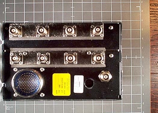
Click to zoom
Application Details
- Equipment Class
- TNB - Licensed Non-Broadcast Station Transmitter
- Date of Grant
- Apr 25, 2001
- Application Purpose
- Original Equipment
- Date of Application
- Apr 24, 2001
- Equipment Note
- Multi-Hazard Awareness unit
- Frequency Range
- 1030.00000000 - 1030.00000000
- Company
- Honeywell International Inc.
- Country
- United States
Documents & Files

Document Text
Text extracted from the exhibit documents filed with the FCC. Open a document above to read the original.
Users Manual
P R E L I M I N A R Y - S U B J E C T T O C H A N G E W I T H O U T N O T I C E SYSTEM INSTALLATION MANUAL KMH 880/KTA 870 MULTI-HAZARD AWARENESS SYSTEM/TRAFFIC ADVISORY SYSTEM MANUAL NUMBER 006-10609-0000 REVISION 0 OCTOBER, 2000 P R E L I M I N A R Y - S U B J E C T T O C H A N G E W I T H O U T N O T I C E WARNING PRIOR TO THE EXPORT OF THIS DOCUMENT, REVIEW FOR EXPORT LICENSE REQUIREMENT IS NEEDED. COPYRIGHT NOTICE ©2000 HONEYWELL INTERNATIONAL INC. Reproduction of this publication or any portion thereof by any means without the express written permission of Honeywell Interna- tional Inc. is prohibited. For further information contact the Manager, Technical Publications,Honeywell International Inc., ONE TECHNOLOGY CENTER, 23500 West 105th Street, Olathe KS 66061 Tele- phone: (913) 782-0400. P R E L I M I N A R Y - S U B J E C T T O C H A N G E W I T H O U T N O T I C E SYSTEM INSTALLATION MANUAL KMH 880/KTA870 MULTI-HAZARD AWARENESS SYSTEM/TRAFFIC ADVISORY SYSTEM P R E L I M I N A R Y - S U B J E C T T O C H A N G E W I T H O U T N O T I C E The binder(s) required to hold this publication(s) are available at an additional cost and may be ordered from: Honeywell One Technology Center 23500 West 105th Street Olathe, Kansas, 66061 Telephone 1-800-757-8999 Orders must specify part number, description, and the quantity. Use the following list to complete the order PART NUMBERDESCRIPTION 006-03140-0001(1) inch Binder. 006-03140-0002(1.5) inch Binder. 006-03140-0003(2) inch Binder. 006-03140-0004(3) inch Binder. 006-03140-0005(4) inch Post Binder. WARNING Prior to Export of this Document, review for export license requirement is needed. COPYRIGHT NOTICE ©2000 Honeywell International Inc. Reproduction of this publication or any portion thereof by any means without the express written permission of Honeywell International Inc. is prohibited. For further information contact the Man- ager, Technical Publications, Honeywell International Inc., One Technology Center, 23500 West 105th Street Olathe KS 66061 Telephone: (913) 782-0400. P R E L I M I N A R Y - S U B J E C T T O C H A N G E W I T H O U T N O T I C E B BB BKMH880/KTA 870 Rev 0, October/200010609I00.ZIPCDLPage R- 1 REVISION HISTORY AND INSTRUCTIONS MANUAL KMH 880/KTA 870 System Install Manual REVISION 0, October, 2000 PART NUMBER 006-10609-0000 Add, delete or replace pages as indicated below and retain all tabs and dividers. Insert this page immediately behind the title page as a record of revisions. This revision level of this manual consists of the following individual publications: PAGE ACTION Initial Release Insert Entire Manual P R E L I M I N A R Y - S U B J E C T T O C H A N G E W I T H O U T N O T I C E B BB BKMH880/KTA 870 Page R- 210609I00.ZIPCDLRev 0, October/2000 THIS PAGE IS RESERVED P R E L I M I N A R Y - S U B J E C T T O C H A N G E W I T H O U T N O T I C E B BB BKMH 880/KTA 870 Rev 0, October/200010609I00.ZIPCDLTOC- i SECTION I GENERAL INFORMATION 1.0INTRODUCTION ....................................................................................1.1 1.1 PURPOSE ..............................................................................................1-1 1.2APPLICABILITY OF THE SYSTEM MANUAL .......................................1-2 1.2.1 Equipment Applicability ..........................................................................1-2 1.3SYSTEM DESCRIPTION .......................................................................1-2 1.3.1 Basic EGPWS System ...........................................................................1-2 1.3.2 Basic TAS System .................................................................................1-3 1.3.3 System Components ..............................................................................1-3 1.3.4 System Operation ..................................................................................1-5 1.4TECHNICAL CHARACTERISTICS ........................................................1-9 1.5UNIT AND ACCESSORIES SUPPLIED ................................................1-12 1.5.1 TAS Processor Unit ................................................................................1-12 1.5.2 Configuration Module .............................................................................1-12 1.5.3 Antennas ................................................................................................1-13 1.6INSTALLATION ACCESSORIES SUPPLIED ........................................1-14 1.6.1 KMH 820/KTA 810 Installation Kit ..........................................................1-14 1.6.2 Antenna Installation Kits..........................................................................1-15 1.6.3 Databases ...............................................................................................1-15 1.7ACCESSORIES REQUIRED BUT NOT SUPPLIED ..............................1-16 1.7.1 Temperature Probe ................................................................................1-16 1.7.2 GPS Antenna Splitter ..............................................................................1-16 1.7.3 Miscellaneous ........................................................................................1-17 1.7.4 Cable And Wire ......................................................................................1-17 1.8LICENSE REQUIREMENTS ..................................................................1-17 1.9INSTRUCTIONS FOR CONTINUED AIRWORTHINESS ......................1-17 1.9.1 KMH 820/KTA 810 Unit...........................................................................1-18 1.9.2 Annunciators/Relays ...............................................................................1-18 1.9.3 GPS Antenna ..........................................................................................1-18 1.9.4 Gps Antenna Splitter ...............................................................................1-18 1.9.5 Temperature Probe ................................…
Text truncated - open the document above for the full version.
Users Manual
Pilot’s Guide KTA870/ KMH880 B Traffic Advisory System/ Multi-Hazard Awareness System Rev. 0006-18265-0000 N The information contained in this manual is for reference use only. If any information contained herein conflicts with similar information contained in the Airplane Flight Manual Supplement, the information in the Airplane Flight Manual Supplement shall take precedence. WARNING Prior to export of this document, review for export license requirement is needed. COPYRIGHT NOTICE ©2000 Honeywell International Inc. Reproduction of this publication or any portion thereof by any means without the express written permission of Honeywell International Inc. is prohibited. For further information contact the Manager, Technical Publications; Honeywell; One Technology Center; 23500 West 105th Street; Olathe, Kansas 66061. Telephone: (913) 782-0400. KTA 870/KMH 880 Pilot's Guide Preliminary Rev 0006-18265-0000 1 SYSTEM COMPONENTS TRAFFIC DISPLAYS: KMD 850 Compatible Radar Indicators via GC 362A, Compatible EFIS. TAS CONTROLS KMD 850 CP 66B TCAS I Controller Discretes KTA 870 & KA 815 W/ OPTIONAL OMNI. System Components KMU 820/KTA 810 Block Diagram 2 Preliminary Rev 0006-18265-0000 INTRODUCTION TAS (an acronym formed from the phrase Traffic Advisory System) is an airborne system used for detecting and tracking aircraft near your own aircraft. TAS includes a TAS processor, antennas, a traffic dis- play and a means to control the system. The TAS processor and antennas detect and track other aircraft by interrogating their transponders. Aircraft detected, tracked, and displayed by TAS are referred to as Intruders. TAS analyzes the transponder replies to determine range, bearing and relative altitude, if the Intruder is report- ing altitude. Should the TAS processor determine that a possible colli- sion hazard exists, it issues visual and aural advisories to the crew. The visual advisory is shown by symbols on the traffic display. Complementing the traffic display, TAS provides appropriate synthe- sized voice announcements in the cockpit. A complete list of traffic symbols and announcements is given in the Theory of Operation and Symbology section of this Pilot’s Guide. TAS is unable to detect any Intruding aircraft without an operat- ing transponder. TAS can detect and track aircraft with either an ATCRBS (operating in Mode A or C) or Mode S transpon- ders. The traffic display shows the Intruding aircraft’s position. TAS identi- fies the relative threat of each Intruder by using various symbols and colors. The Intruder’s altitude, relative to your own aircraft’s altitude, is annunciated if the Intruder is reporting altitude. A trend arrow is used to indicate if the Intruder is climbing or descending more than 500 feet per minute. TAS traffic may be displayed on a weather radar indica- tor, on a dedicated TAS display, on a TAS compatible EFIS Display Unit or a TA/VSI (combination traffic display and vertical speed instru- ment). TAS modes and functions are controlled by switches located on a TAS control panel or in combination with various other controls. A description of controls is given in the Controls and Displays section of this Pilot’s Guide. ATC procedures and the “see and avoid concept” will continue to be the primary means of ensuring aircraft separation. However, if com- munication is lost with ATC, TAS adds a significant backup for colli- sion avoidance. Introduction KTA 870/KMH 880 Pilot's Guide Preliminary Rev 0006-18265-0000 3 TAS: •Is compatible with the ATC System •Determines if a threat exists from ATCRBS or Mode S Transponder equipped aircraft •Provides display and audio announcement to the crew - Position information displayed on a traffic display - Synthesized voice •Incorporates sensor inputs and sophisticated algorithms to minimize nuisance visual and aural annunciations. EGPWS: Introduction 4 Preliminary Rev 0006-18265-0000 Theory of Operation and Symbology THIS PAGE INTENTIONALLY LEFT BLANK KTA 870/KMH 880 Pilot's Guide Preliminary Rev 0006-18265-0000 5 SECTION I : THEORY OF OPERATION AND SYMBOLOGY SECTION I DESCRIBES TAS AND EGPWSTHEORY OF OPERA- TION AND SYMBOLOGY. Theory of Operation and Symbology 6 Preliminary Rev 0006-18265-0000 TAS OPERATION TAS monitors the airspace surrounding your aircraft by interrogating the transponder of the Intruding aircraft. The interrogation reply enables TAS to compute the following information about the Intruder: 1. Range between your aircraft and the Intruder. 2. Relative bearing to the Intruder. 3. Altitude and vertical speed of the Intruder, if the Intruder is reporting altitude. 4. Closing rate between the Intruder and your aircraft. Using this data TAS predicts the time to, and the separation at, the Intruder’s Closest Point of Approach (CPA). Should TAS predict that certain safe boundaries may be violated, it will issue a Traffic Advisory (TA) to alert the crew that closing traffic is nearby. TAS SENSITIVITY LEVEL TAS separates the surrounding airspace into two altitude layers. A different sensitivity threshold level for issuing TAs (traffic advisories) is applied to each altitude layer. Lower altitudes have less sensitive TA threshold levels to prevent unnecessary advisories in the higher traffic densities anticipated at lower flight levels, i.e., terminal areas. TAS has two sensitivity levels (SL) which are described in Table 1, TAS Sensitivity Levels. SL A is invoked using the following order of precedence: (1) when the TAS aircraft is below 2,000 feet AGL (if equipped with radio altimeter) OR (2) when the landing gear is Extended (no radio altimeter installed). SL B occurs under all other flight conditions. Table 2, Typical Traffic Advisory Conditions for Sensitivity Levels describes what conditions will cause a TA to be issued. If aircraft is not equipped with either a radio altimeter or retractable landing gear, TAS will stay in SL B at all times. Sensitivity Level DESCRIPTION SL A In sensitivity level A, TAS performs surveilla…
Text truncated - open the document above for the full version.
External Photos
Front Close-up of Front Diagnal View Le ft Side Right Side Back
ID Label/Location Info
Honeywell International Inc. NOTES: 1. MATERIAL: MATTE MYLAR #9905P .005 THICK. REAR SURFACE SILVER TAMPERPROOF COATING. PERMANENT ACRYLIC PRESSURE SENSITIVE ADHESIVE, WITH PROTECTIVE LINER. TAG TO WITHSTAND -55°C TO +100°. OVERLAMINATE TO BE #9903 OR EQUIVALENT 2. LETTERS, MOD BLOCK AND LOGO TO BE BLACK, BACKGROUND TO BE SILVER. 3. TAG TO BE CONSECUTIVELY STAMPED WITH SERIAL NO. AS REQUIRED BY PURCHASE ORDER. 4. ARTWORK FOR -0001 USE PAGE ONE, -0002 USE PAGE TWO. 5. TAG SIZE: 1.400 x 0.750. KTA 810 DO 178B SOFTWARE LEVEL C RTCA DO160D FCC ID: ASYKMH820 057-05824-0001 Honeywell International Inc. 057-05824-0002 KMH 820 DO 178B SOFTWARE LEVEL C RTCA DO160D FCC ID: ASYKMH820 4:1 REV. -
ID Label/Location Info
NAMEPLATE LOCATION Note nameplate location shown as 057-05824-001 in lower left corner of page 2 of 300-05638-000.
Operational Description
Honeywell International Inc. Document Name: KMH_FCC_Technical Information Page 1 of 10 Technical Information for FCC CERTIFICATION FOR THE KMH 820 MULTI-HAZARD AWARENESS UNIT KTA 810 TRAFFIC ADVISORY UNIT Revised March 30, 2001 Written by: _________________ Rex Darrow & Terry Michie Staff Engineers Reviewed by: ________________ David Nelson IPDS Team Leader ________________ Date Honeywell International Inc. Document Name: KMH_FCC_Technical Information Page 2 of 10 1. General This Technical Information is in support of Honeywell’s application for certification of the KTA 810 / KMH 820 unit. 1.1 System Description . The KTA 810 / KMH 820 is the processing unit for the Honeywell KTA 870 / KMH 880 system respectively and contains two separate processors: the TAS processor and the GA EGPWS processor (the KTA 810 contains only the TAS processor). The TAS portion of the KTA 810 / KMH 820 provides intruder surveillance and tracking for transponder-equipped aircraft and generates traffic advisories for these intruders. The TAS portion of the KTA 810 / KMH 820 tracks intruders under surveillance and analyzes range and range rate data, and altitude and altitude rate of the traffic to determine whether the intruder represents a threat. KTA 810 / KMH 820 communicates this information to the pilot via a display and/or aural annunciations. Pilot selectable functions of the KTA 810 / KMH 820 are controlled from a control panel or discrete controls. The TAS portion of the KTA 810 / KMH 820 is very similar to a “baseline” TCAS I (AlliedSignal TPU 66A) as described in RTCA DO-197A. For example, the TAS portion only performs omni-directional Mode C interrogations. It does not perform Mode S interrogations. The GA EGPWS display functionality has been previously certified and is being used without modification. This GA EGPWS portion provides a visual representation of the terrain ahead and around the aircraft. The flight crew is alerted of impending terrain by voice and by terrain color on the display. The KTA 810 / KMH 820 interfaces to the following systems on board the aircraft: altitude encoding altimeters, magnetic heading, GPS (KMH 820 only), outside air temperature (KMH 820 only), optional radar altitude (TAS only), optional attitude, aircraft weight-on-wheels, landing gear position, and L Band suppression bus. 1.2 Model Numbers Being Certified. The KMH 820 with the GPS card, represents the most complete unit and therefore it will be the unit tested. The KTA 810 (traffic only) and KMH 820 without GPS are to be covered by similarity. Models being certified: KMH 820Part No. 066-01175-2101 KMH 820Part No. 066-01175-0101 (same as 066-01175-2101 except without GPS card) Honeywell International Inc. Document Name: KMH_FCC_Technical Information Page 3 of 10 KTA 810Part No. 066-01152-0101 (same as 066-01175-2101 except without EGPWS module) Note: FCC ID:ASYKMH820 is to be applied to all above models. 2. Required Items 2.1 (2.1033,c,1) Name Note: Parentheses in titles indicate applicable paragraphs in CFR. The name of the manufacturer and the name of the applicant, which are the same is: Honeywell International Inc. One Technology Center 23500 W. 105 th Street Olathe, Kansas 66061 2.2 (2.1033,c,2) FCC Identifier FCC Identifier is ASYKMH820. 2.3 (2.1033,c,3) Installation See the Installation Manual in the document package. 2.4 (2.1033,c,4) Type of Emission Emission type is 18M0V1D. 2.5 (2.1033,c,5) Frequency Range The transmission frequency is 1030 ± 0.200 MHz only. 2.6 (2.1033,c,6) Range of Operating Power Values The rated output power is +53 dBm +/- 2.0 dB. There is no means of manually varying power. Power is automatically reduced in 3 dB steps down to +29 dBm by means of a built-in step attenuator as part of normal system operation. See schematic 002-09038-0010 sheet 2 transmitter schematic under Confidential Materials in document package. 2.7 (2.1033,c,7) Maximum Operating Power The maximum output power is 316 Watts referenced at the unit. Honeywell International Inc. Document Name: KMH_FCC_Technical Information Page 4 of 10 2.8 (2.1033,c,8) Voltage and Current Applied The voltage applied to Q102 is 50 VDC from a regulated supply included in the unit. The pulse current during an RF power pulse is 16 amps. 2.9 (2.1033,c,9) Tune-up Procedure 2.9.1 Set up equipment as in Figure 2. 2.9.2 Refer to schematic 002-09038-0010 and adjust C144, C147, C151, C153, and C155 for peak power at 1030 MHz. 2.9.3 Replace the spectrum analyzer with HP 8991A Peak Power Analyzer as in Figure 1 and further adjust the same capacitors to obtain pulse risetime of 50 to 100 uS, falltime of 50 to 200 uS, and power of 200 to 316 Watts. 2.9.4 Re-connect spectrum analyzer and check for frequency of 1030 ± 0.200 MHz. 2.10 (2.1033,c,10) Schematic Diagrams and Descriptions See schematic 002-09038-0010 sheet 2 transmitter schematic under Confidential Materials in document package. The KTA 810/KMH 820 transmitter includes a 1030 MHz synthesizer for the frequency source. This source is fed through a 6 dB pad and two MMIC switches to the transmitter input stage. The pad and switches provide isolation between the synthesizer source and the transmitter for low leakage during non-transmit times. The transmitter input stage is a low RF power MMIC followed by a 2 W stage which then drives the 1015MP class C medium power amplifier. This is followed with a one pole ceramic band pass filter to reduce the broadband emissions. A 90 W class C power amplifier pre-driver then provides the drive power needed for the TPR400R 400 W class C final power amplifier. The whisper shout attenuator follows this to provide attenuation levels needed for the interrogation with its incremental size of 3 dB (0dB, 3dB, 6dB, .... 24dB). The output of this is steered to either top antenna or bottom antenna by a top/bottom antenna switch circuit and its associated harmonic rejection filter circuit. The output of the unit is +53 dBm +/-2 dB. 2.11 (2.1033,c,11) Identification Pla…
Text truncated - open the document above for the full version.
Parts List/Tune Up Info
Honeywell International Inc. Document Name: KMH_FCC_Technical Information Page 1 of 10 Technical Information for FCC CERTIFICATION FOR THE KMH 820 MULTI-HAZARD AWARENESS UNIT KTA 810 TRAFFIC ADVISORY UNIT Revised March 30, 2001 Written by: _________________ Rex Darrow & Terry Michie Staff Engineers Reviewed by: ________________ David Nelson IPDS Team Leader ________________ Date Honeywell International Inc. Document Name: KMH_FCC_Technical Information Page 2 of 10 1. General This Technical Information is in support of Honeywell’s application for certification of the KTA 810 / KMH 820 unit. 1.1 System Description . The KTA 810 / KMH 820 is the processing unit for the Honeywell KTA 870 / KMH 880 system respectively and contains two separate processors: the TAS processor and the GA EGPWS processor (the KTA 810 contains only the TAS processor). The TAS portion of the KTA 810 / KMH 820 provides intruder surveillance and tracking for transponder-equipped aircraft and generates traffic advisories for these intruders. The TAS portion of the KTA 810 / KMH 820 tracks intruders under surveillance and analyzes range and range rate data, and altitude and altitude rate of the traffic to determine whether the intruder represents a threat. KTA 810 / KMH 820 communicates this information to the pilot via a display and/or aural annunciations. Pilot selectable functions of the KTA 810 / KMH 820 are controlled from a control panel or discrete controls. The TAS portion of the KTA 810 / KMH 820 is very similar to a “baseline” TCAS I (AlliedSignal TPU 66A) as described in RTCA DO-197A. For example, the TAS portion only performs omni-directional Mode C interrogations. It does not perform Mode S interrogations. The GA EGPWS display functionality has been previously certified and is being used without modification. This GA EGPWS portion provides a visual representation of the terrain ahead and around the aircraft. The flight crew is alerted of impending terrain by voice and by terrain color on the display. The KTA 810 / KMH 820 interfaces to the following systems on board the aircraft: altitude encoding altimeters, magnetic heading, GPS (KMH 820 only), outside air temperature (KMH 820 only), optional radar altitude (TAS only), optional attitude, aircraft weight-on-wheels, landing gear position, and L Band suppression bus. 1.2 Model Numbers Being Certified. The KMH 820 with the GPS card, represents the most complete unit and therefore it will be the unit tested. The KTA 810 (traffic only) and KMH 820 without GPS are to be covered by similarity. Models being certified: KMH 820Part No. 066-01175-2101 KMH 820Part No. 066-01175-0101 (same as 066-01175-2101 except without GPS card) Honeywell International Inc. Document Name: KMH_FCC_Technical Information Page 3 of 10 KTA 810Part No. 066-01152-0101 (same as 066-01175-2101 except without EGPWS module) Note: FCC ID:ASYKMH820 is to be applied to all above models. 2. Required Items 2.1 (2.1033,c,1) Name Note: Parentheses in titles indicate applicable paragraphs in CFR. The name of the manufacturer and the name of the applicant, which are the same is: Honeywell International Inc. One Technology Center 23500 W. 105 th Street Olathe, Kansas 66061 2.2 (2.1033,c,2) FCC Identifier FCC Identifier is ASYKMH820. 2.3 (2.1033,c,3) Installation See the Installation Manual in the document package. 2.4 (2.1033,c,4) Type of Emission Emission type is 18M0V1D. 2.5 (2.1033,c,5) Frequency Range The transmission frequency is 1030 ± 0.200 MHz only. 2.6 (2.1033,c,6) Range of Operating Power Values The rated output power is +53 dBm +/- 2.0 dB. There is no means of manually varying power. Power is automatically reduced in 3 dB steps down to +29 dBm by means of a built-in step attenuator as part of normal system operation. See schematic 002-09038-0010 sheet 2 transmitter schematic under Confidential Materials in document package. 2.7 (2.1033,c,7) Maximum Operating Power The maximum output power is 316 Watts referenced at the unit. Honeywell International Inc. Document Name: KMH_FCC_Technical Information Page 4 of 10 2.8 (2.1033,c,8) Voltage and Current Applied The voltage applied to Q102 is 50 VDC from a regulated supply included in the unit. The pulse current during an RF power pulse is 16 amps. 2.9 (2.1033,c,9) Tune-up Procedure 2.9.1 Set up equipment as in Figure 2. 2.9.2 Refer to schematic 002-09038-0010 and adjust C144, C147, C151, C153, and C155 for peak power at 1030 MHz. 2.9.3 Replace the spectrum analyzer with HP 8991A Peak Power Analyzer as in Figure 1 and further adjust the same capacitors to obtain pulse risetime of 50 to 100 uS, falltime of 50 to 200 uS, and power of 200 to 316 Watts. 2.9.4 Re-connect spectrum analyzer and check for frequency of 1030 ± 0.200 MHz. 2.10 (2.1033,c,10) Schematic Diagrams and Descriptions See schematic 002-09038-0010 sheet 2 transmitter schematic under Confidential Materials in document package. The KTA 810/KMH 820 transmitter includes a 1030 MHz synthesizer for the frequency source. This source is fed through a 6 dB pad and two MMIC switches to the transmitter input stage. The pad and switches provide isolation between the synthesizer source and the transmitter for low leakage during non-transmit times. The transmitter input stage is a low RF power MMIC followed by a 2 W stage which then drives the 1015MP class C medium power amplifier. This is followed with a one pole ceramic band pass filter to reduce the broadband emissions. A 90 W class C power amplifier pre-driver then provides the drive power needed for the TPR400R 400 W class C final power amplifier. The whisper shout attenuator follows this to provide attenuation levels needed for the interrogation with its incremental size of 3 dB (0dB, 3dB, 6dB, .... 24dB). The output of this is steered to either top antenna or bottom antenna by a top/bottom antenna switch circuit and its associated harmonic rejection filter circuit. The output of the unit is +53 dBm +/-2 dB. 2.11 (2.1033,c,11) Identification Pla…
Text truncated - open the document above for the full version.
Test Report
Page 1 of 24 Report No: FC01-023 HONEYWELL INTERNATIONAL INC. TEST REPORT FOR THE KMH 820 MULTI-HAZARD AWARENESS UNIT AND KTA 810 TRAFFIC ADVISORY UNIT FCC PART 87 SUBPART D COMPLIANCE DATE OF ISSUE: MARCH 12, 2001 PREPARED FOR: Honeywell International Inc. 23500 West 105th St – MS #56 Olathe, KS 66061-6615 P.O. No: A00007055 W.O. No: 75294 PREPARED BY: Joyce Walker CKC Laboratories, Inc. 5473A Clouds Rest Mariposa, CA 95338 Date of test: March 5-7, 2001 Report No.: FC01-023 This report contains a total of 24 pages and may be reproduced in full only. Partial reproduction may only be done with the written consent of CKC Laboratories, Inc. Page 2 of 24 Report No: FC01-023 PART 87 TABLE OF CONTENTS Administrative Information .........................................................................................................3 Summary of Results.....................................................................................................................4 Frequency Range Tested..............................................................................................................4 EUT Operating Frequency ...........................................................................................................4 Required EUT Changes To Comply ............................................................................................4 Approvals.....................................................................................................................................4 Equipment Under Test (EUT) Description ..................................................................................5 Equipment Under Test .................................................................................................................5 Peripheral Devices .......................................................................................................................5 2.1033(c)(4) – Type of Emissions ...............................................................................................6 2.1033(c)(5) – Frequency Range .................................................................................................6 2.1033(c)(6) – Operating Power ..................................................................................................6 2.1033(c)(7) – Maximum Power Rating ......................................................................................6 2.1033(c)(14)/2.1046/87.131 - RF Power Output........................................................................7 2.1033(c)(14)/2.1047(a) - Modulation Characteristics - Audio Frequency Response .................9 2.1033(c)(14)/2.1047(b)/ 87.141 - Modulation Characteristics – Modulation Limiting Response 9 2.1033(c)(14)/87.135 - Occupied Bandwidth ..............................................................................10 2.1033(c)(14)/2.1051/87.139 - Spurious Emissions At Antenna Terminal .................................11 2.1033(c)(14)/2.1053/87.139 - Field Strength of Spurious Radiation .........................................14 2.1033(c)(14)/2.1055/87.133 - Frequency Stability.....................................................................20 Appendix A: Information About Test Data Sheet Headers .........................................................23 Page 3 of 24 Report No: FC01-023 CKC Laboratories, Inc. has received Certificates of Accreditation from the following agencies: A2LA (USA); DATech (Germany); BSMI (Taiwan); Nemko (Norway); and GOST (Russia). CKC Laboratories, Inc has received test site Registration Acceptance from the following agencies: FCC (USA); VCCI (Japan); and Industry Canada. CKC Laboratories, Inc. has received Letters of Acceptance through an MRA for the following agencies: ACA/NATA (Australia); SABS (South Africa); SWEDAC (Sweden); Radio Communications Agency (RA); HOKLAS (Hong Kong); Bakom (Swiss); BIPT (Belgium); Denmark Telestyrelsen; RvA (Netherlands); SEE (Luxembourg) SITTEL (Bolivia); and UKAS (UK). ADMINISTRATIVE INFORMATION DATE OF TEST: March 5-7, 2001 DATE OF RECEIPT: March 5, 2001 PURPOSE OF TEST: To demonstrate the compliance of the KMH 820 Multi-Hazard Awareness Unit and KTA 810 Traffic Advisory Unit with the requirements for FCC Part 87 Subpart D. TEST METHOD: FCC Part 87 MANUFACTURER: Honeywell International Inc. 23500 West 105th St – MS #56 Olathe, KS 66061-6615 REPRESENTATIVE: Larry Haddix TEST LOCATION: CKC Laboratories, Inc. 5473A Clouds Rest Mariposa, CA 95338 Page 4 of 24 Report No: FC01-023 SUMMARY OF RESULTS As received, the Honeywell International Inc. KMH 820 Multi-Hazard Awareness Unit and KTA 810 Traffic Advisory Unit was found to be fully compliant with the following standards and specifications: United States ! FCC Part 87 Subpart D The results in this report apply only to the items tested, as identified herein. FREQUENCY RANGE TESTED Radiated: 24 MHz – 11 GHz. EUT OPERATING FREQUENCY 1030 MHz REQUIRED EUT CHANGES TO COMPLY None. APPROVALS QUALITY ASSURANCE:TEST PERSONNEL: Dennis Ward, Quality ManagerRandy Clark, EMC Engineer Chuck Kendall, EMC/Lab Manager Page 5 of 24 Report No: FC01…
Text truncated - open the document above for the full version.
Contact Information
Applicant
Dawn M. Gidner(FCC Coordinator)
Technical Contact
CKC Laboratories, Inc.Tracy Phillips
[email protected]800-500-4362
5473A Clouds Rest · Mariposa, California · United States
Non-Technical Contact
CKC Laboratories, Inc.Joyce Walker
[email protected]800-500-4362
Test Firm
CKC Laboratories, Inc.Steve Behm
Technical Specifications
| # | Rule Parts | Frequency Range | Power Output | Emission | Tolerance |
|---|---|---|---|---|---|
| 1 | 87 | 1.03 GHz - 1.03 GHz | 316 W | 18M0V1D | 0.0194000000 % |
Other Applications from Honeywell International Inc.
ASYKTR2280B
Feb 02, 2026Multi-mode Digital Radio
Equipment Class
TNB - Licensed Non-Broadcast Station Transmitter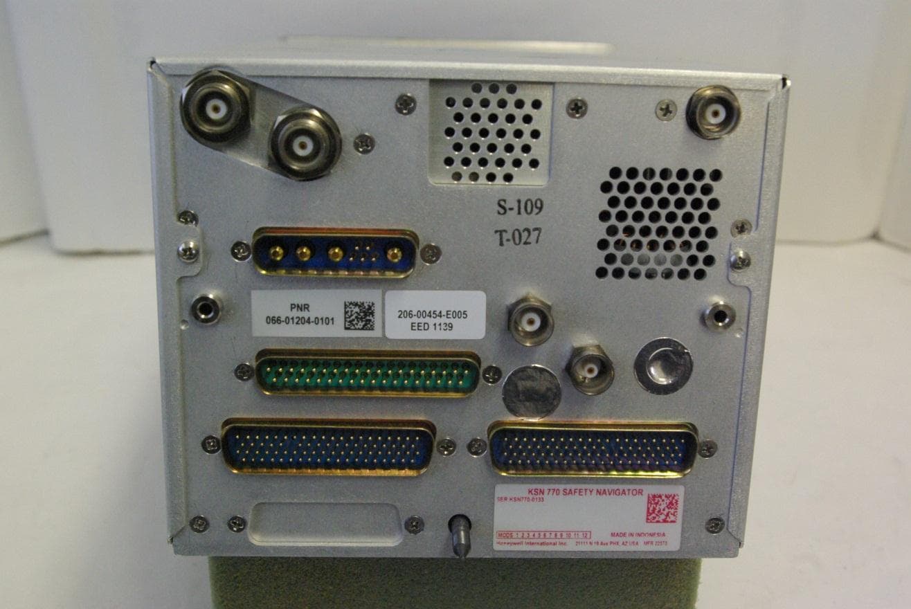
ASYKSN770
Mar 06, 2013Aviation Communications Transceiver
Equipment Class
TNB - Licensed Non-Broadcast Station Transmitter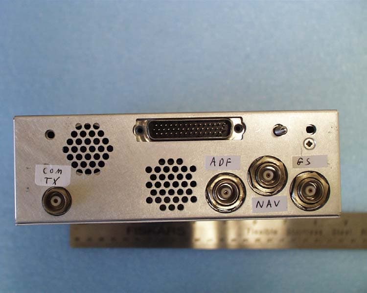
ASYKTR2280
Aug 20, 2006AVIATION SERVICES TRANSMITTER
Equipment Class
TNB - Licensed Non-Broadcast Station Transmitter
ASYMCX-1000A
Feb 15, 2006AVIATION DATA COMMUNICATIONS TRANSMITTER
Equipment Class
TNB - Licensed Non-Broadcast Station Transmitter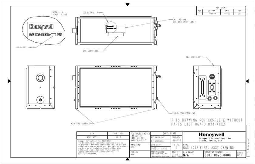
ASYKHF1050
Mar 27, 2003High Frequency Communications Transceiver
Equipment Class
TNB - Licensed Non-Broadcast Station Transmitter