ASYKX165AKX165A VHF Navigation / Communications Transceiver
Honeywell International Inc.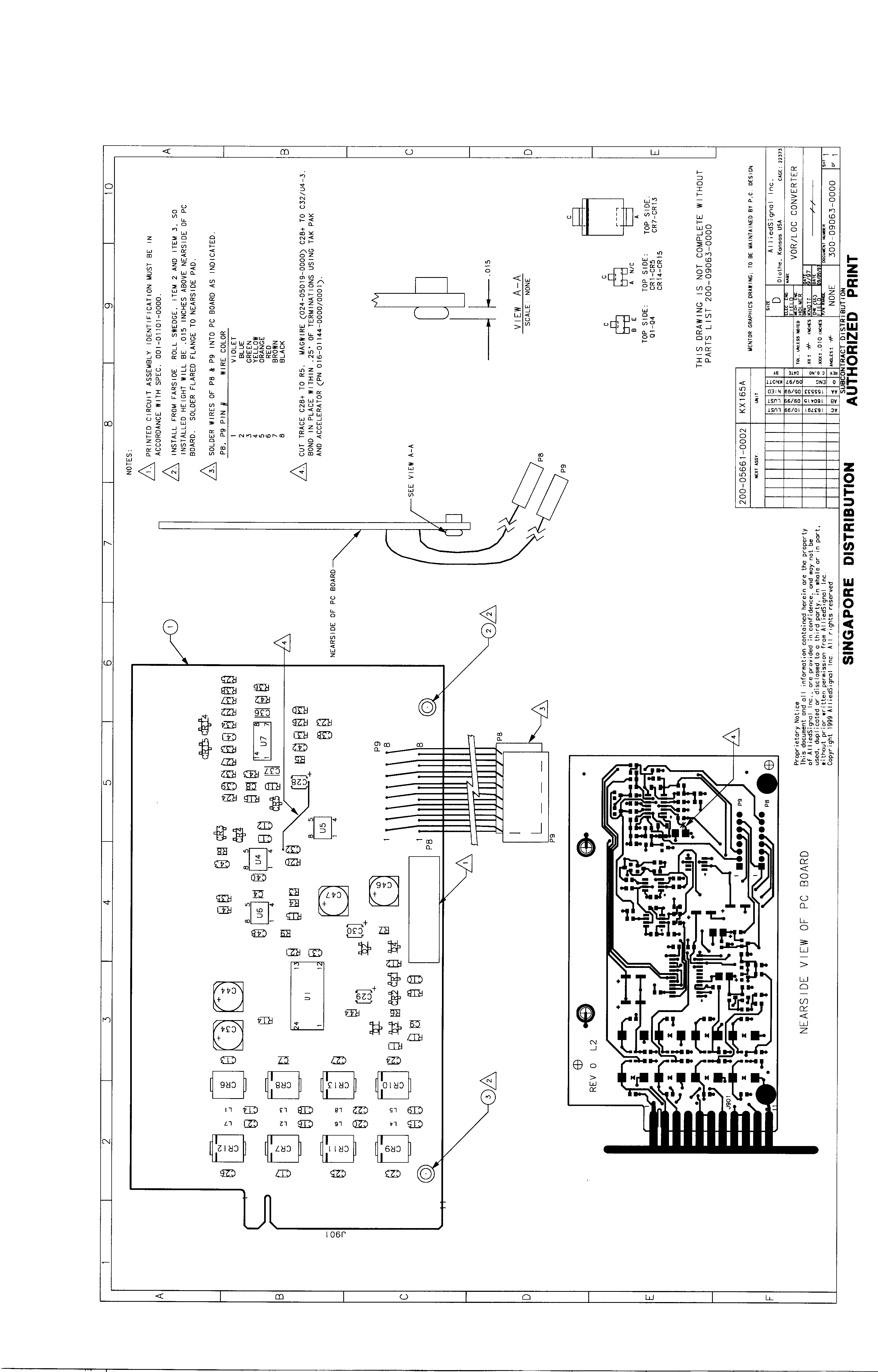
Click to zoom
Application Details
- Equipment Class
- TNB - Licensed Non-Broadcast Station Transmitter
- Date of Grant
- Apr 11, 2000
- Application Purpose
- Original Equipment
- Date of Application
- Feb 14, 2000
- Equipment Note
- KX165A VHF Navigation / Communications Transceiver
- Frequency Range
- 118.00000000 - 137.00000000
- Company
- Honeywell International Inc.
- Country
- United States
Documents & Files
Document Text
Text extracted from the exhibit documents filed with the FCC. Open a document above to read the original.
Users Manual
INSTALLATION MANUAL KX 155A/165A COMM/NAV SYSTEM MANUAL NUMBER 006-10542-0002 REVISION 2, APRIL 2000 PRELIMINARY - SUBJECT TO CHANGE WITHOUT NOTICE WARNING Prior to Export of this Document, review for export license requirement is needed. COPYRIGHT NOTICE ©2000 Honeywell International Inc. Reproduction of this publication or any portion thereof by any means without the express written permission of Honeywell is prohibited. For further information contact the Manager, Technical Publications, Honeywell, One Technology Center, 23500 West 105th Street Olathe KS 66061 Telephone: (913) 782-0400. PRELIMINARY - SUBJECT TO CHANGE WITHOUT NOTICE BENDIX/KING KX 155A/165A COMM/NAV SYSTEM 10542I02.ZIPRCDPage 1-1 Rev 2, Apr/2000 SECTION I GENERAL INFORMATION 1.1INTRODUCTION This manual contains information relative to the physical, mechanical, and electrical characteris- tics of the Bendix/King Silver Crown KX155A VHF COMM Transceiver/Navigation/VOR/LOC Glideslope Receiver. Installation and operating procedures are also included. Information relative to the maintenance, alignment, and procurement of replacement parts may be found in the KX155A Maintenance/Overhaul Manual, P/N 006-15542-XXXX. 1.2EQUIPMENT DESCRIPTION The KX155A is a VHF NAV/COMM Transceiver which provides the following functions. A.Two-way voice communication within the frequency range of 118.00 MHz to 136.975 MHz (760 Channels) in 25 kHz increments. B.Reception of navigation signals within the frequency range of 108.00 MHz to 117.95 MHz in 50 kHz increments (200 channels). C.Optional reception of glideslope signals within the frequency range of 329.15 MHz to 335.00 MHz in 150 kHz increments (40 channels). D.High level speaker audio output plus limited audio intercom inputs and out- puts. E.Provides a count down timer. The KX155A is a panel mounted unit. Connections to the unit are made through one 36 and one 50 pin Molex printed circuit board edge connector and three BNC coax connectors at the rear of the unit. Electrically, the KX155A consists of the following sections: •COMM Transmitter •COMM Receiver •NAV Receiver •Main Board •Glideslope Receiver and Converter (Optional) •Gas Discharge Display •4 Ω Audio Amplifier The KX155A is backward compatible with existing KX155 installations. See Section 2.3 Additional Installation Notes for details. PRELIMINARY - SUBJECT TO CHANGE WITHOUT NOTICE BENDIX/KING KX 155A/165A COMM/NAV SYSTEM Page 1-210542I02.ZIPRCD Rev 2, Apr/2000 1.3TECHNICAL CHARACTERISTICS Table 1-1 KX155A/KX165A Technical Specifications KX155A/KX165A GENERAL SPECIFICATIONS ENVIRONMENTAL TSO COMPLI- ANCE: RTCA DO-160C, Eurocae ED-14C Env Cat (see Appendix E) TEMPERATURE RANGE:-20°C to +55°C with short time operation at +70°C. (Operational to -40°C) ALTITUDE:-15,000 feet to 50,000 feet WEIGHT: KX 155AVERSIONSWEIGHTMtg Rack (nominal)w/hardware 069-01032-0101 4.2 lbs (1.9 kg) 1.1 lbs (0.5 kg) 069-01032-0201 3.7 lbs (1.7 kg) 1.1 lbs (0.5 kg) VERSIONSWEIGHTMtg Rack (nominal)w/hardware KX 165A069-01033-0101 4.0 lbs (1.8 kg) 1.1 lbs (0.5 kg) 069-01033-0201 4.0 lbs (1.8 kg) 1.1 lbs (0.5 kg) PHYSICAL DIMENSIONS (NOMINAL) : Width:6.25 inches (15.875 cm) Height:2.00 inches (5.08 cm) Depth:10.16 inches (25.81 cm) to end of connector MOUNTING:Panel mounted, no shock mounting required POWER CONSUMPTION: RECEIVETRANSMIT VERSIONS:TYP.PEAK PRELIMINARY - SUBJECT TO CHANGE WITHOUT NOTICE BENDIX/KING KX 155A/165A COMM/NAV SYSTEM 10542I02.ZIPRCDPage 1-3 Rev 2, Apr/2000 069-01032-01010.8 A2.2 A6.0 A (MAX) 069-01032-02010.8 A2.2 A6.0 A (MAX) 069-01033-01010.6 A 0.7 A 4.0 A (MAX) 069-01033-02010.6 A 0.7 A 4.0 A (MAX) NOTE: Peak currents occur only when installation is configured for the 4Ω audio output & both COMM and NAV volumes are adjusted to full. Specifications are at 25°C unless otherwise specified. COMM TRANSCEIVER TSO COMPLIANCE: Transmit:C37d (DO-186A, Class 4 - all flavors/ Class 4 & 6 069-01033-0201) Receive:C38d (DO-186A, Class C & D - all flavors/ Class C, D, & E 069-01033-0201) APPLICABLE DOCUMENTS:RTCA DO-186A, DO-160C, *EUROCAE ED-23B, ED-14C DUTY CYCLE:10%, 4.5 minutes receive, 0.5 minutes transmit FREQUENCY RANGE:118.000 MHz to 136.975 MHz COMM TRANSMITTER POWER OUTPUT:10 Watts minimum 10 Watts typical (KX 155A pre-Mod 5) MODULATION:70% minimum modulation capability with less than 15% distortion. Audio leveling circuit used. SIDETONE OUTPUT:Adjustable up to 100 mW ( 5.1 mW Mod 1 w/o Mod 6) into 500 Ω headphones MICROPHONE:Standard carbon or dynamic mic containing transistorized pre-amp. (Must provide 100 mVrms into 100 Ω load.) PRELIMINARY - SUBJECT TO CHANGE WITHOUT NOTICE BENDIX/KING KX 155A/165A COMM/NAV SYSTEM Page 1-410542I02.ZIPRCD Rev 2, Apr/2000 HARMONIC CONTENT:-56 dBc, minimum. Typically greater than -60 dBc HIGH TEMPERATURE PROTEC- TION: If the transmitter and modulator circuits become hot enough to potentially damage any components in the transceiver, a protection circuit will automatically reduce the transmitter power consumption and output power. TRANSMITTER TIME OUT:If MIC key is enabled for greater than 30 ( Nominal) sec- onds, the transmitter will shut down. The transmitter is re- set upon release of MIC key. PRELIMINARY - SUBJECT TO CHANGE WITHOUT NOTICE BENDIX/KING KX 155A/165A COMM/NAV SYSTEM 10542I02.ZIPRCDPage 1-5 Rev 2, Apr/2000 COMM RECEIVER RECEIVER SENSITIVITY:-107 dBm (2μV hard) or less for 6 dB S + N/N with 1,000 Hz tone modulated 30 %. RECEIVER SELECTIVITY: Class C & D operating modes6 dB bandwidth ±8.0 kHz, minimum 60 dB bandwidth ±22.0 kHz, maximum Class E operating mode6 dB bandwidth ±2.778 kHz, minimum 60 dB bandwidth ±7.37 kHz, maximum RECEIVER AUDIO OUTPUT:100 mW into 500 Ωs minimum. AGC CHARACTERISTICS:From -93 dBm to -33 dBm audio output will not vary more than 3 dB. Active from no signal to +3 dBm. SQUELCH:Automatic squelch (internally adjustable carrier to noise setting) with manual disable and carrier squelch override. Both squelch adjustments are externally accessible. The automatic squelch ha…
Text truncated - open the document above for the full version.
Cover Letter(s)
FCC-00-539 February 15 , 2000 FAA Spectrum Engineering Division (AES-500) 800 Independence Avenue SW Washington, D.C. 20591 Dear Sir: Honeywell International Inc. is currently developing modifications to our KX 165 VHF Navigation / Communications Transceiver to meet a European mandated 8.33Khz channel bandwidth. The modifications to the unit are extensive enough to require that the model name change to a KX 165A VHF Navigation / Communications Transceiver. As required by CFR Title 47, Subpart D, Paragraph 87.147 (d), Honeywell International Inc. hereby submits notification of FCC Certification application for the KX 165A Navigation / Communication Transceiver. Equipment characteristics are as follows: Equipment Description:KX 165A Navigation / Communication Transceiver PN 069-01033-0201 Manufacturer’s Identification:Honeywell International Inc. FCC ID: ASYKX165A Antenna Characteristics:Conventional 50 Ohm Vertically Polarized Omnidirectional Rated Output Power:10 Watts Minimum, 12 Watts Maximum referenced at the antenna input Emission Type:A3E Emission Characteristics:Voice Modulated, AM Frequency:118.000 Mhz to 136.975 Mhz Essential receiver characteristics if protection is required: No Protection Required If there are any questions concerning the data in this submittal, please contact Art Ercolani at Honeywell International Inc. in Olathe, Kansas, 913-712-2487. Thank you for your prompt attention in this manner. Sincerely, Art Ercolani Senior DER Staff Engineer FCC Coordinator Honeywell International Inc. (913) 712-2487
Cover Letter(s)
Enclosures: FCC Form 159 FCC Form 731 Check for $475.00 Waiver Request Approval Letter (DA 98-2037) dated October 7, 1998 Notification Letter to the FAA Application for Certification Installation Manual006-10542-0002 Alignment Procedure001-05082-0000 Theory of OperationN/A Serial Number Label057-05964-0000 Schematics: Main002-09059-0040 Transmitter002-09062-0020 VOR/LOC Converter002-09063-0000 Glideslope002-09060-0000 Directional Coupler002-09362-0010 IF Filter002-09709-0000 TX Filter002-09174-0020 TX Audio Adapter002-09680-0000 Front Panel Board Schematic002-09057-0000 COM/VOR Receiver002-09061-0010 Assembly Drawings: Main Board300-09059-0040 Transmitter Board300-09062-0020 VOR/LOC Converter300-09063-0000 Glideslope Board300-09060-0000 Glideslope Assembly300-09447-0000 Directional Coupler300-09362-0010 IF Filter300-09709-0000 TX Filter Board300-09174-0020 TX Audio Adapter Board300-09680-0000 Front Panel Display Board Ass’y300-09057-0000 Bezel Assembly300-05672-0000 COM/VOR Receiver Assembly300-09061-0000 RF Power Transistor Assembly300-09532-0000 Top Cover300-05661-0020 Base300-05660-0020 Final Assembly Drawing300-09095-0010
Operational Description
BENDIX/KING KX 165A NAV/COMM TRANSCEIVER Page 4-1 RCD:15610M00 Rev 0, Apr/2000 SECTION IV THEORY OF OPERATION 4.1GENERAL This manual cover s KX 165A configurations. 4.1.1KX 165A FEATURES The KX 165A is a single unit, panel mounted communication transceiver/navigation receiver with glideslope receiver and VOR/LOC Converter. The functional capabilities are: A.A microprocessor controlled communication transceiver which operates from 118.00 MHz to 136.975 MHz in 8.33 kHz increments providing 2280 channels. 32 program- mable memories. B.A microprocessor controlled navigation receiver for VOR/LOC signals from 108.00MHz to 117.95MHz in 50kHz increments providing 200 channels. C.A microprocessor controlled glideslope receiver operating from 329.15 MHz to 335.00 MHz in 150kHz increments for 40 glideslope channels. D.A microprocessor controlled VOR/LOC converter capable of calculating and display- ing bearing VOR radial digitally. E.A microprocessor controlled VOR/LOC converter I/O board for use with indicators that do not contain an internal converter. F.DME Channeling 1.Provides data to interface with KN 62/A/64 DME or the KDI 572/574 or KPI 553A indicator which will in turn control the KN 63 DME or the KDM 706 DME. 2.Provide data to interface with KA 120 Adapter which will in turn channel 2 x 5 or slip code DME’s. G.Digital Display of: 1.Communication “USE” and “STANDBY” frequencies. 2.Navigation “USE and “STANDBY” frequencies. 3.VOR Radial information displayed in navigation “STANDBY” window. 4.Internal course deviation indicator for VOR and localizer. 5.Elapsed timer: countdown and elapsed time. H.Navigation and Communication frequency information is stored in a non-volatile memory. Information is stored when the radio is turned off and will re-channel to the same frequencies when turned on. I.Front panel lighting of bezel and knobs. PRELIMINARY - SUBJECT TO CHANGE WITHOUT NOTICE BENDIX/KING KX 165A NAV/COMM TRANSCEIVER Page 4-2 RCD:15610M00 Rev 0, Apr/2000 4.2BLOCK DIAGRAM THEORY OF OPERATION Refer to Figure 4-1 for the following block diagram explanation. The KX 165A Navcom transceiver includes a VHF communication receiver and transmitter, VOR Navigation receiver, glideslope re- ceiver, VOR/LOC converter I/O, front panel with display, power supply, and central processing unit with various interface circuits. The CPU controls the functions of the unit, and includes memory, I/O, and several other functions. Each major function block diagram is described in subsequent sections. Figure 4-1 KX 165A Block Diagram PRELIMINARY - SUBJECT TO CHANGE WITHOUT NOTICE BENDIX/KING KX 165A NAV/COMM TRANSCEIVER Page 4-3 RCD:15610M00 Rev 0, Apr/2000 4.2.1COM RECEIVER Refer to figure 4-2. The front end of the Com receiver employs a dual-gate FET RF amplifier em- bedded in a 4-pole tracking preselector. This RF amplifier FET also provides RF AGC action. A doubly-balanced mixer converts the RF to a first IF at 21.4 MHz and is followed by a bipolar IF amplifier. In radios which use 25 kHz bandwidths exclusively, the IF amplifier is followed by six poles of crystal filtering. The IF amplifier is followed by an IF filter board in Radios which are both 25 kHz and 8.33 kHz channel capable. This IF filter board switches the IF between a six pole 25 kHz (wide) crystal filter and an 8.33 kHz (narrow) eight pole filter. Selecting wide or narrow chan- nel tuning determines which filter is used. The filtered 21.4 MHz output is amplified by another IF amplifier transistor and passed to the inputs of an AM Receiver IC. This IC amplifies the first IF signal, mixes it down to 450 kHz, passes the signal through an exter- nal ceramic filter before it is further amplified in the receiver IC and detected. The detected signal is used to develop IF AGC voltage and the detected signal is also output from the IC to drive audio filters and amplifiers. RF AGC voltage is derived from the IF AGC voltage. A high-side-injection first LO signal is derived from a synthesizer circuit which employs a dual-modulus Synthesizer IC, an active integrator, a loop filter and a VCO. Amplification of the VCO output is accomplished with a MMIC. In transmit the synthesizer locks up on the desired transmit frequency and a discrete bipolar amplifier is used to amplify the MMIC output to provide a drive signal to the transmitter. The 20.95MHz synthesizer reference frequency is generated by a crystal oscillator on 25kHz units, and by a TCXO on radios which are 25/8.33kHz capable. This reference frequency also serves as the second LO injection signal. The detected audio signal from the AM IC is lowpass filtered and amplified. A compressor circuit provides a relatively constant audio output level re- gardless of the percent of modulation of the incoming signal. Squelch action is controlled by both an audio noise detector squelch and a carrier squelch signal derived off the RF AGC. Squelching is accomplished in the audio path on the Receiver Board as well as by another squelch gate on the Main Board. On the Main Board, the audio signal passes through the Com volume control to the audio amplifier. PRELIMINARY - SUBJECT TO CHANGE WITHOUT NOTICE BENDIX/KING KX 165A NAV/COMM TRANSCEIVER Page 4-4 RCD:15610M00 Rev 0, Apr/2000 THIS PAGE RESERVED PRELIMINARY - SUBJECT TO CHANGE WITHOUT NOTICE BENDIX/KING KX 165A NAV/COMM TRANSCEIVER Page 4-5 RCD:15610M00Rev 0 Apr/2000 Figure 4-2 KX155A NAV/COM Receiver - Main Board Audio Circuitry Sheet 1 of 2 PRELIMINARY - SUBJECT TO CHANGE WITHOUT NOTICE BENDIX/KING KX 165A NAV/COMM TRANSCEIVER Page 4-7 RCD:15610M00Rev 0 Apr/2000 Figure 4-2 KX155A NAV/COM Receiver - Main Board Audio Circuitry Sheet 2 PRELIMINARY - SUBJECT TO CHANGE WITHOUT NOTICE BENDIX/KING KX 165A NAV/COMM TRANSCEIVER Page 4-9 RCD:15610M00 Rev 0, Apr/2000 4.2.2TRANSMITTER The transmitter produces an amplitude modulated (AM) signal within the COM BAND frequency range of 118 to 137 MHz. The output power of the signal at the COM ANT is 10 watts minimum. Refer to figure…
Text truncated - open the document above for the full version.
Parts List/Tune Up Info
Honeywell International Inc.KPN 001-05082-0000 Page 1 of 30 Rev - KX165A ALIGNMENT PROCEDURE AlliedSignal Inc. One Technology Center 23500 West 105 th St. Olathe, Kansas 66061 Prepared by:Larry Phillips Larry Phillips Project Engineer Approved by:Greg Plumberg Greg Plumberg Test Engineer Final Approval Date:12/30/96 Honeywell International Inc.KPN 001-05082-0000 Page 2 of 30 Rev - PROPRIETARY NOTICE The information disclosed within this document or separately supplied in furtherance of this document includes proprietary rights of AlliedSignal Avionics Incorporated. Neither this document nor the information disclosed herein or of a supplementary nature shall be reproduced or transferred to other documents or used or disclosed to others for manufacturing purposes, or for any other purposes, except as specifically authorized in writing by AlliedSignal Avionics Incorporated. AlliedSignal Avionics Inc. is a wholly-owned subsidiary of AlliedSignal, Inc. TRADEMARK NOTICE "Bendix/King" and the BENDIX/KING logo are registered trademarks of AlliedSignal, Inc., U.S. Patent & Trademark Office. DOCUMENT MAINTENANCE This document was created using Microsoft Word for Windows version 6.0. REVISION HISTORY RevisionECOByDateDescription of Change -Initial Release Honeywell International Inc.KPN 001-05082-0000 Page 3 of 30 Rev - TABLE OF CONTENTS 1. INTRODUCTION5 1.1Purpose5 1.2Definitions and abbreviations5 1.2.1Definitions5 1.2.2Abbreviations5 1.3References7 1.3.1Traceability references7 1.4Assumptions and dependencies8 1.5Required Test Equipment9 2. SUB-ASSEMBLY ALIGNMENT PROCEDURE9 2.1Comm/NAV Receiver Alignment9 2.1.1Equipment connections, EEPROM initialization and PC control panel setting9 2.1.2Test Equipment initial setting10 2.1.3 Reference Oscillator, COM VCO, TX Drive and NAV VCO alignment.11 2.1.3.1 25 KHz Radio11 2.1.3.2 8.33 KHz Radio11 2.1.3.3 25 KHz / 8.33 KHz Radio11 2.1.4COM RF Preselector and IF Filter Alignment for 200-09061-0010 Boards11 2.1.4.1PRESELECTOR11 2.1.4.1PRESELECTOR Alternate Procedure12 2.1.4.3IF FILTER12 2.1.5COM RF AGC Alignment13 2.1.6COM RF Squelch Alignment13 2.1.7NAV RF Preselector Alignment13 2.1.8NAV IF Filter Alignment14 2.1.9NAV RF AGC Alignment14 2.1.10 EEPROM Temperature Compensation15 2.2Transmitter19 2.3Main Board19 2.4Audio Board20 2.5Front Panel20 2.6Glideslope Receiver20 3. UNIT LEVEL ALIGNMENT21 3.1Main Board23 Honeywell International Inc.KPN 001-05082-0000 Page 4 of 30 Rev - 3.2 Display23 3.2.1Photo Cell23 3.2.2Display Brightness23 3.3Communication Receiver Alignment23 3.3.1Reference Oscillator23 3.3.2COM VCO and TX Drive23 3.3.3COM RF Preselector and IF Filter Alignment for 200-09061-0010 Boards24 3.3.4COM RF AGC Alignment24 3.3.5COM RF Squelch Alignment25 3.3.5.125 KHz Radio25 3.3.5.28.33 KHz Radio25 3.4Navigation Receiver Alignment25 3.4.1NAV VCO25 3.4.2NAV RF Preselector Alignment25 3.4.3NAV IF Filter Alignment26 3.4.4 NAV RF AGC Alignment26 3.4.5PLL (manual adjustment)26 3.4.5.2REV 1 PCB26 3.4.6LOC converter27 3.4.6.1Internal Converter Center Offset (KX 165A)27 3.4.6.2Internal Converter Course Width (KX 165A)27 3.4.6.3LOC Centering27 3.4.7VOR converter27 3.4.8VOR/LOC Composite Level27 3.4.9Ident (manual adjustment)27 3.5Comm Transmitter28 3.5.1Selection of C1 SAT (Select at Test) Value Error! Bookmark not defined. 3.5.2Power and Modulation28 3.5.3Sidetone Level28 3.5.4Intercom28 3.6Glideslope Receiver Alignment29 3.6.1Reference Oscillator29 3.6.2VCO Adjustment29 3.6.3RF Front End Alignment29 3.6.4R.F. A.G.C. Adjustment30 3.6.5Convertor Width and Centering Adjustment30 3.6.6Glideslope Receiver Centering Alignment30 Honeywell International Inc.KPN 001-05082-0000 Page 5 of 30 Rev - 1.INTRODUCTION 1.1Purpose This procedure describes the alignment for sub-assemblies as well as the initial unit level alignment for the KX 155A/165A. 1.2Definitions and abbreviations 1.2.1 Definitions Standard VOR test signal: An RF carrier, amplitude modulated simultaneously a) 30+1% by a “reference phase signal,” composed of a 9960 Hz subcarrier, which is, in turn, frequency modulated at a deviation ratio of 16 by a 30 +0.1% Hz signal, and b) 30 + 1% by a 30+0.1% Hz “variable phase signal” which can be varied in phase with respect to the 30 Hz FM of the reference phase signal. Standard LOC centering signal: An RF carrier modulated simultaneously by a 20 + 1% 90 Hz + 0.3% and a 20 + 1% 150 Hz +0.3%. The difference in depth of modulation is less than 0.002. Standard glideslope centering signal: An RF carrier modulated simultaneously by a 40 + 1% 90 Hz +0.3% and a 40 + 1% 150 Hz +0.3%. The difference in depth of modulation between the 90 and 150 Hz signals is less than 0.002. Standard glideslope deviation signal: An RF carrier modulated simultaneously by a 40 + 1% 90 Hz +0.3% and a 40 + 1% 150 Hz +0.3%. The difference in depth of modulation is .091 +0.002. 1.2.2 Abbreviations AbbreviationDescription " inches of Mercury Ω ΩΩ Ω ohm μ μμ μ A microampere μ μμ μ F microfarad μ μμ μ V microvolt μ μμ μ W microwatt °C degrees Celsius °K degrees Kelvin A ampere AGC automatic gain control AGL above ground level APT airport ASCII American Standard Code for Information Interchange Honeywell International Inc.KPN 001-05082-0000 Page 6 of 30 Rev - AbbreviationDescription ATE Automated Test Equipment CDI course deviation indicator col column comm communication CW continuous wave (unmodulated) dB decibel dBm decibels relative to 1 mW est estimated FSS Flight Service Station ft foot GHz Gigahertz GPS global positioning system HIRF high intensity radiated field hP hecto Pascals Hz Hertz ICAO International Civil Aviation Organization ident identifier in. inch j -1 K Ω ΩΩ Ω kilo-ohm KHz kilohertz KPN King part number KW kilowatt lb pound LRU line replaceable unit M Ω ΩΩ Ω megaohm mA milliampere mag magnetic mB millibar mF millifarad MHz Megahertz mic microphone min minute MSL mean sea level mV millivolt mV millivolt mW milliwatt NDB nondirectional beacon nF nanofarads nm nautical mile p page pF pic…
Text truncated - open the document above for the full version.
Test Report
TEST REPORT For APPLICATION of CERTIFICATION For Honeywell International Inc. 23500 West 105th Street Olathe, KS 66061 Greg Triplett, Engineering Team Leader MODEL: KX165A P/N 069-01033-XXXX FREQUENCY: 118.0-136.990 MHz FCC ID: ASYKX165A Test Date: January 17, 2000 Certifying Engineer: Scot D. Rogers ROGERS LABS, INC. 4405 West 259th Terrace Louisburg, KS 66053 Phone: (913) 837-3214 FAX: (913) 837-3214 This report shall not be reproduced except in full, without the written approval of the laboratory. This report must not be used by the client to claim product endorsement by NVLAP or any agency of the U.S. Government. ROGERS LABS, INC. Honeywell International Inc. 4405 West 259 th Terrace MODEL: KX165A P/N: 069-01033-xxxx Louisburg, KS 66053 Test #:000117 FCC ID#: ASYKX165A Phone/Fax: (913) 837-3214 Test to: FCC Parts 2 and 87 Page 2 of 26 CERTIFICATION\ALLIEDKX165 02/07/00 TABLE OF CONTENTS FORWARD:3 LIST OF TEST EQUIPMENT3 2.1033(C)APPLICATION FOR CERTIFICATION4 2.1046RF POWER OUTPUT5 Measurements Required:5 Test Arrangement:5 Results:5 2.1047MODULATION CHARACTERISTICS8 Measurements Required:8 Test Arrangement:8 Results:8 2.1049OCCUPIED BANDWIDTH10 Measurements Required:10 Test Arrangement:10 Results:10 2.1051 SPURIOUS EMISSIONS AT ANTENNA TERMINALS12 Measurements Required:12 Test Arrangement:12 Results:13 2.1053FIELD STRENGTH OF SPURIOUS RADIATION14 Measurements Required:14 Test Arrangement:14 Results:16 2.1055FREQUENCY STABILITY17 Measurements Required:17 Test Arrangement:17 Results:18 APPENDIX20 ROGERS LABS, INC. Honeywell International Inc. 4405 West 259 th Terrace MODEL: KX165A P/N: 069-01033-xxxx Louisburg, KS 66053 Test #:000117 FCC ID#: ASYKX165A Phone/Fax: (913) 837-3214 Test to: FCC Parts 2 and 87 Page 3 of 26 CERTIFICATION\ALLIEDKX165 02/07/00 FORWARD: In accordance with the Federal Communications Code of Federal Regulations, dated October 1, 1998, Part 2 Subpart J, Paragraphs 2.907, 2.911, 2.913, 2.915, 2.925, 2.926, 2.1031 through 2.1057, Part 87, Subchapter D, Paragraphs 87.131 through 87.147, and FCC document FCC98-58, the following is submitted: List of Test Equipment A Hewlett Packard 8591EM and or 8562A Spectrum Analyzer was used as the measuring device for the emissions testing. The analyzer settings used are described in the following table. Refer to the Appendix for a complete list of Test Equipment. HP 8591EM SPECTRUM ANALYZER SETTINGS CONDUCTED EMISSIONS: RBW AVG. BW DETECTOR FUNCTION 9 kHz 30 kHz Peak/Quasi Peak RADIATED EMISSIONS (30 – 1000 MHz): RBW AVG. BW DETECTOR FUNCTION 120 kHz 300 kHz Peak/Quasi Peak HP 8562A SPECTRUM ANALYZER SETTINGS RADIATED EMISSIONS (1 – 40 GHz): RBW AVG. BW DETECTOR FUNCTION 1 MHz 1 MHz Peak/Average ANTENNA CONDUCTED EMISSIONS: RBW AVG. BW DETECTOR FUNCTION 120 kHz 300 kHz Peak ROGERS LABS, INC. Honeywell International Inc. 4405 West 259 th Terrace MODEL: KX165A P/N: 069-01033-xxxx Louisburg, KS 66053 Test #:000117 FCC ID#: ASYKX165A Phone/Fax: (913) 837-3214 Test to: FCC Parts 2 and 87 Page 4 of 26 CERTIFICATION\ALLIEDKX165 02/07/00 2.1033(c)Application for Certification (1) Manufacturer: Honeywell International Inc. 23500 West 105th Street Olathe, KS 66061 (2) Identification: Model: KX165A P/N: 069-01033-0201 S/N: Y237 FCC I.D.: ASYKX165A (3) Instruction Book: Refer to exhibit for Draft Instruction Manual. (4) Emission Type: 6K00A3E (5) Frequency Range: 118.0 - 136.990 MHz, Adjustable in 8.33 or 25 kHz steps. (6) Operating Power Level: 10 Watts (7) Max P o : 10 Watts (8) Power into final amplifier: 41.25 Watts (27.5V @ 1.5A). (9) Tune Up Procedure for Output Power: Refer to Exhibit for Transceiver Alignment Procedure. (10) Circuit Diagrams; description of circuits, frequency stability, spurious suppression, and power and modulation limiting: Refer to Exhibit for Circuit Diagrams. Refer to Exhibit for Theory of Operation. (11) Photograph or drawing of the Identification Plate: Refer to Exhibit for Photograph or Drawing. (12) Drawings of Construction and Layout: Refer to Exhibit for Drawings of Components Layout and Chassis Drawings. (13) Detail Description of Digital Modulation: Not applicable. ROGERS LABS, INC. Honeywell International Inc. 4405 West 259 th Terrace MODEL: KX165A P/N: 069-01033-xxxx Louisburg, KS 66053 Test #:000117 FCC ID#: ASYKX165A Phone/Fax: (913) 837-3214 Test to: FCC Parts 2 and 87 Page 5 of 26 CERTIFICATION\ALLIEDKX165 02/07/00 2.1046RF Power Output Measurements Required: Measurements shall be made to establish the radio frequency power delivered by the transmitter into the standard output termination. The power output shall be monitored and recorded and no adjustment shall be made to the transmitter after the test has begun, except as noted below: If the power output is adjustable, measurements shall be made for the highest and lowest power levels. Test Arrangement: The radio frequency power output was measured at the antenna terminal by replacing the antenna with a spectrum analyzer, 50-dB attenuation and cable. The spectrum analyzer had an impedance of 50Ω to match the impedance of the standard antenna. A HP 8591EM Spectrum Analyzer was used to measure the radio frequency power at the antenna port. The data was taken in dBm and converted to watts as shown in the following Table. Refer to Figures 1 through 4 showing the output power of the transmitter. Data taken per Paragraph 2.1046(a) and applicable parts of Part 87. P dBm = power in dB above 1 milliwatt. Milliwatts = 10 (PdBm/10) Watts = (Milliwatts)(0.001)(W/mW) 40.0 dBm = 10 (40.0/10) = 10,000 mW = 10 Watts Results: REQUENCYP dBm P mw P w 118.000 40.0 10,000 10 127.500 40.0 10,000 10 136.000 39.9 9,908 10 136.990 40.0 10,000 10 The specifications of Paragraph 2.1046(a) and applicable Parts of 87 are met. There are no deviations to the specifications. TRANSMITTER SPECTRUM ANALYZER ATTENUATION ROGERS LABS, INC. Honeywell International Inc. 4405 West 259 th Terrace MODEL: KX165A P/N: 069-01033-xxxx Louisburg, KS 66053 Test #:000117 FCC ID#: ASYKX165A Phon…
Text truncated - open the document above for the full version.
Contact Information
Applicant
Dawn M. Gidner(FCC Coordinator)
Technical Contact
Honeywell International Inc.Art Ercolani
[email protected]913-712-2487
One Technology Center · Olathe, Kansas · United States
Non-Technical Contact
Honeywell International Inc.Art Ercolani
[email protected]913-712-2487
Test Firm
Rogers Labs, Inc.Scot Rogers
Technical Specifications
| # | Rule Parts | Frequency Range | Power Output | Emission | Tolerance |
|---|---|---|---|---|---|
| 2 | 87 | 118 MHz - 137 MHz | 10 W | 5K00A3E | 5 ppm |
Other Applications from Honeywell International Inc.
ASYKTR2280B
Feb 02, 2026Multi-mode Digital Radio
Equipment Class
TNB - Licensed Non-Broadcast Station Transmitter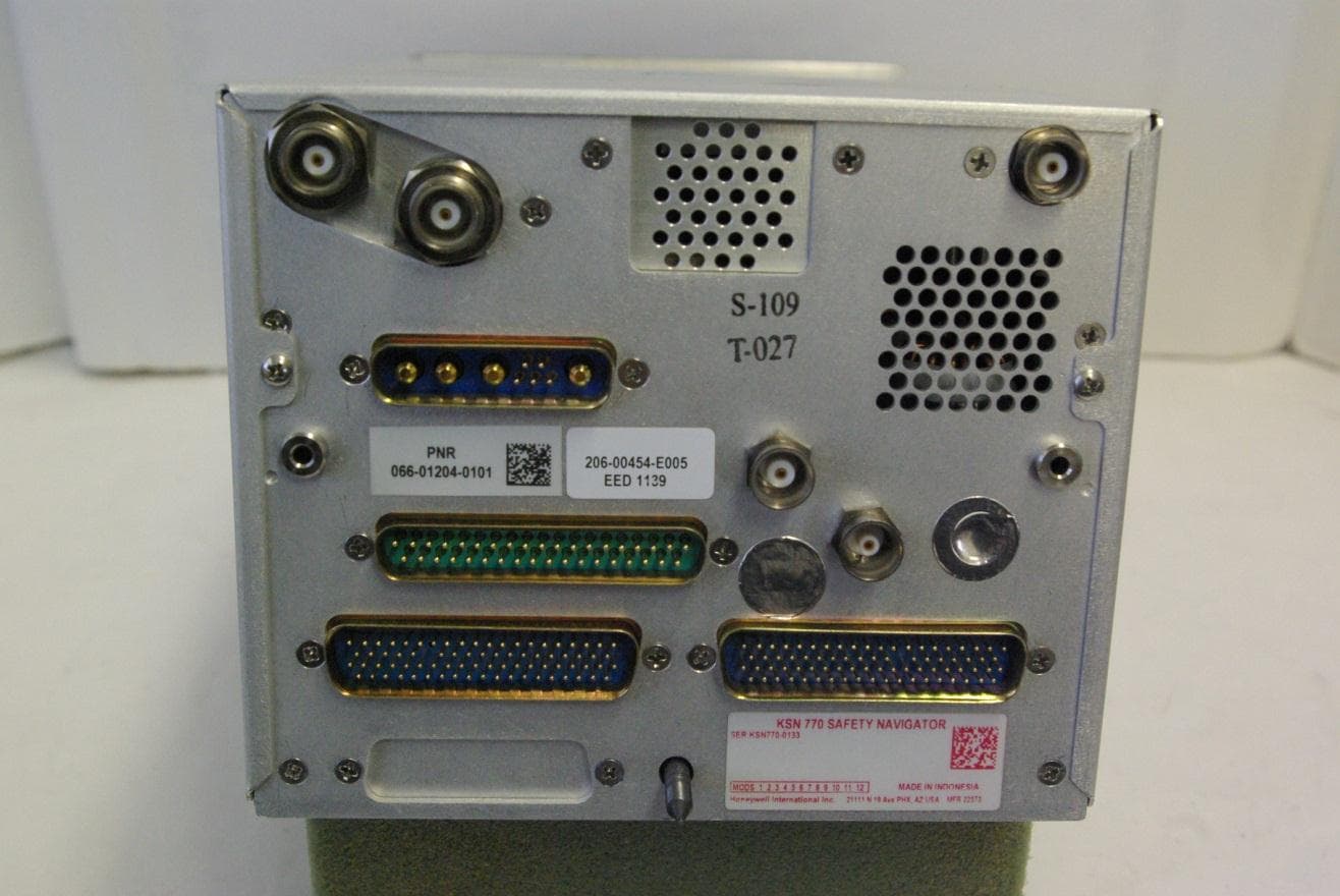
ASYKSN770
Mar 06, 2013Aviation Communications Transceiver
Equipment Class
TNB - Licensed Non-Broadcast Station Transmitter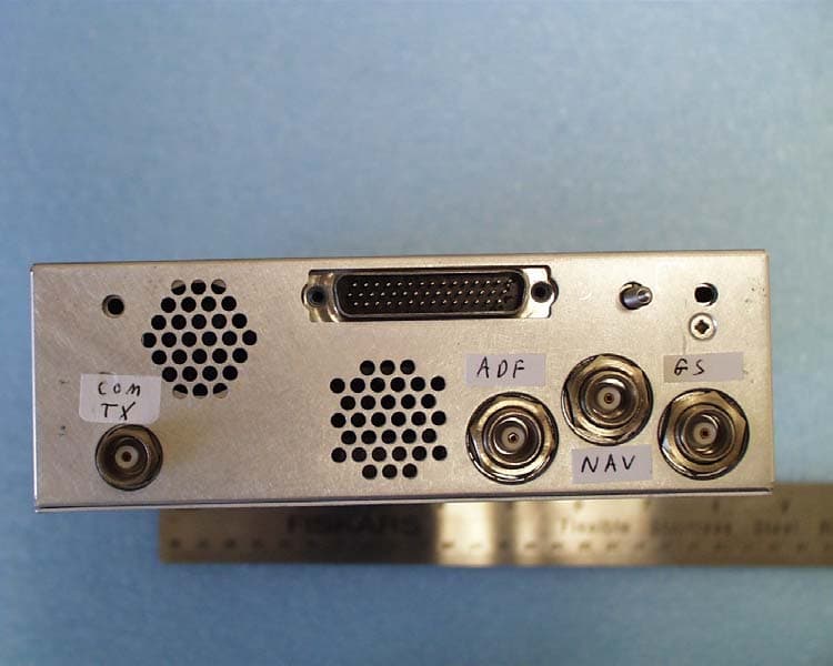
ASYKTR2280
Aug 20, 2006AVIATION SERVICES TRANSMITTER
Equipment Class
TNB - Licensed Non-Broadcast Station Transmitter
ASYMCX-1000A
Feb 15, 2006AVIATION DATA COMMUNICATIONS TRANSMITTER
Equipment Class
TNB - Licensed Non-Broadcast Station Transmitter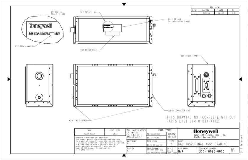
ASYKHF1050
Mar 27, 2003High Frequency Communications Transceiver
Equipment Class
TNB - Licensed Non-Broadcast Station Transmitter