ATI9R3HRD007017" DIGITAL AUDIO VIDEO PLAYER
Action Electronics Co.,Ltd.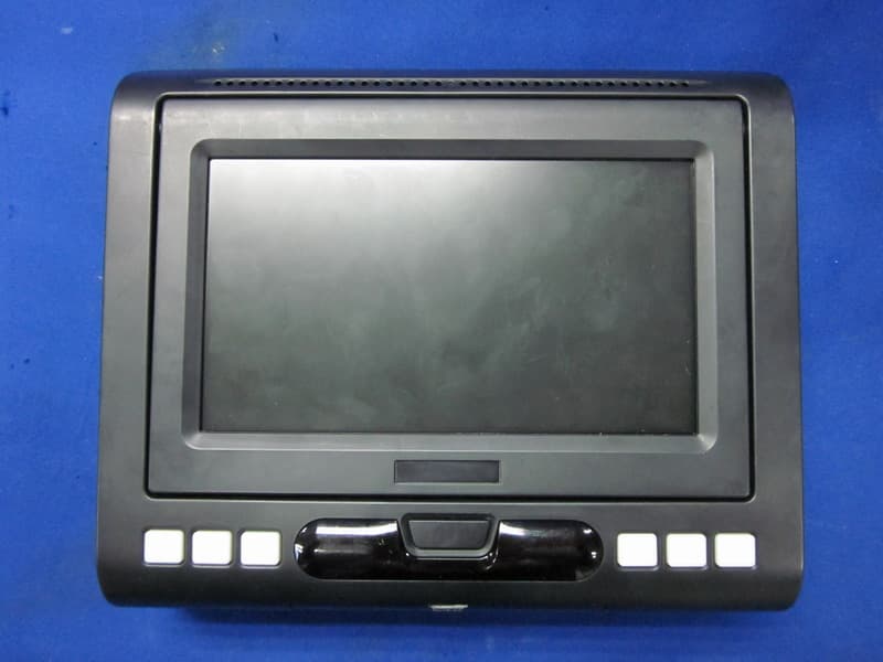
Click to zoom
Application Details
- Equipment Class
- DXX - Part 15 Low Power Communication Device Transmitter
- Date of Grant
- Mar 24, 2011
- Application Purpose
- Original Equipment
- Date of Application
- Mar 22, 2011
- Equipment Note
- 7" DIGITAL AUDIO VIDEO PLAYER
- Frequency Range
- 88.50000000 - 107.90000000
- Company
- Action Electronics Co.,Ltd.
- Country
- Malaysia
Documents & Files
Document Text
Text extracted from the exhibit documents filed with the FCC. Open a document above to read the original.
Users Manual
AVXMTGHR1D 7“ LCD Monitor with DVD Player Build In for Rear Entertaiment Owner’s Manual / Installation Guide CONTENTS 1 CONTROLS AND INDICATORS DIAGRAM9------------- IMPORTANT NOTICE2---------------------------------- MATERIAL TO USE IN THIS PACKAGE3------------------ HEADREST COVER REPLACEMENT4------------------- VEHICLE PREPARATION5---------------------------- Wireless FM Modulator6------------------------------ AVXMTGHR1D WIRING DIAGRAM7--------------------- FEATURES8------------------------------------------ SPECIFICATIONS 8 ------------------------------------ REMOTE CONTROL OPERATION10-------------------- MENU ADJUSTMENT11-------------------------------- SETTINGS AND ADJUSTMENTS12---------------------- Selecting Folders and Songs 13 -------------------------- TROUBLESHOOTING14------------------------------- Installation of headrest products require careful planning and preparation. Be extremely careful of seats that have airbags built into them. Keep wiring away from any air bag wiring (usually identified by yellow connectors and yellow wire jackets). Damage to air bag wiring can result in personal injury to vehicle occupants. If you have any questions regarding wire routing or installation in a vehicle, please contact Audiovox Technical Support at 1-800-225-6074. When connecting power and ground in a mobile video installation, insure that the ACC wire is fused at the point where it is connected to the vehicle ACC wiring. Failure to do so can result in damage to the vehicle if a short circuit develops between the vehicle connection point and the mobile video product. IMPORTANT NOTICE An LCD panel and/or video monitor may be installed in a motor vehicle and visible to the driver if the LCD panel or video monitor is used for vehicle information, system control, rear or side observation or navigation. If the LCD panel or video monitor is used for television reception, video or DVD play, the LCD panel or video monitor must be installed so that these features will only function when the vehicle is in “park” or when the vehicle’s parking brake is applied. An LCD panel or video monitor used for television reception, video or DVD play that operates when the vehicle is in gear or when the parking is not applied must be installed to the rear of the driver’s seat where it will not be visible, directly or indirectly, to be operator of the motor vehicle. Licensed under one or more of the following patents: Patent NOS. 7,245,274 , 6,899,365 and 6,678,892 2 CAUTION: TO REDUCE THE RISK OF ELECTRIC SHOCK, DO NOT REMOVE COVER (OR BACK). NO USER-SERVICEABLE PARTS INSIDE. REFER SERVICING TO QUALIFIED SERVICE PERSONNEL. RISK OF ELECTRONIC SHOCK DO NOT OPEN CAUTION Any changes or modifications not expressly approved by the party responsible for compliance could void the user’s authority to operate the equipment. MATERIAL TO USE IN THIS PACKAGE: Note: Monitor include headrest cable. 1)System Monitor () Monitor with DVD Player AVXMTGHR1DAVXMTGHR1D Note:The AVXMTGHR1D monitor has been designed to be interchangeable from one headrest to the other. The headrests will still have the Green and Blue DIN cables on them and should be connected to their respective connectors. 1) Remote Control (P/N 42-2S-39000G) -(1pcs) 3) 8PINS (M) DIN CABLE_RED WITH RCA CABLE (P/N)-(1pcs)45-2Z-08200G 4) 8PIN (Male) AV OUT to RCA (P/N)-(1pcs)45-2S-08230G 2) AUX PIGTAIL (P/N)-(1pcs)112B3227 6) (P/N)-(1box) Plastic Pole 83 2S 0002-- 5) (P/N)-(2pcs) Heat Shrink Tube 31 02 10700G-- 3 HEADREST COVER REPLACEMENT: 1.Unscrew the two screws,and removed the screen. Unscrew Remove 2.Remove the.Hearest cover 3.replace the leather with the matching color cover. Push 4.connected the cable,lock the monitor's buttons into position and push it in place to lock. 4 Tighten screws 5.Tighten screws VEHICLE PREPARATION 1) Read the manuals and get familiar with the electrical requirements and connections. 2) Prepare the vehicle by removing any interior trim necessary to gain access to the vehicle's wiring as well as all areas where interconnecting wire harnesses will be located. (Refer to the Installation Procedure). The mounting method, and the location will vary from vehicle to vehicle, so this manual will only focus for the installation of the Monitors in the supplied configuration: 3) Locate an accessory power source (+12VDC present when the ignition key is in the accessory and run positions. 0VDC should be present when the ignition key is in the OFF position), and a good ground. Generally, these wires can be located at the ignition switch or fusebox. (Ensure that the switched power is fused at the source. Failure to do so may result in vehicle wiring damage.) 4) Run the wiring harnesses throughout the vehicle as necessary. (Refer to the Wiring Diagrams on page 7, as well as the wiring instructions for the individual components and accessory options being installed). Be sure, that all the wiring is protected from sharp edges and is routed in such a manner that it will not be pinched, when it is fully installed. Be sure to leave enough slack in the wiring at each component to allow sufficient working room. Be sure to leave enough slack in the monitor cables to allow the headrest to move up or down, and the seat to move backward and forward. 5) Remove all the components from their packaging and then place them in the vehicle at their respective locations. 6) Install the Headrests: a. Remove vehicle's original Headrests. b. Hold the Headrest above the seat and insert the two cables into the headrest support tube holes. Make sure that the headrest is in the correct position (Display facing the rear). c. Route the cables through the seat back and out the bottom of the seat. d. Place the Headrest support tubes into the support tube holes while pulling the cables to remove the slack. Be sure to leave enough slack in the monitor cables to allow the headrest to move up or down. NOTE: 5 7) Connect all the components together (electrically) and verify proper …
Text truncated - open the document above for the full version.
External Photos
R AUDIX Technology (Shenzhen) Co., Ltd. FCC ID:ATI9R3HRD00701 page Audix Technology (Shenzhen) Co., Ltd. Report No. ACS-F11047 9-2 9. PHOTOGRAPH OF EUT Figure 1 General Appearance of the EUT Figure 2 General Appearance of the EUT R AUDIX Technology (Shenzhen) Co., Ltd. FCC ID:ATI9R3HRD00701 page Audix Technology (Shenzhen) Co., Ltd. Report No. ACS-F11047 8-3 Figure 3 General Appearance of the EUT Figure 4 Inside of the EUT
ID Label/Location Info
Label location
Internal Photos
R AUDIX Technology (Shenzhen) Co., Ltd. FCC ID:ATI9R3HRD00701 page Audix Technology (Shenzhen) Co., Ltd. Report No. ACS-F11047 8-3 Figure 3 General Appearance of the EUT Figure 4 Inside of the EUT R AUDIX Technology (Shenzhen) Co., Ltd. FCC ID:ATI9R3HRD00701 page Audix Technology (Shenzhen) Co., Ltd. Report No. ACS-F11047 8-4 Figure 5 Inside of the EUT Figure 6 Inside of the EUT R AUDIX Technology (Shenzhen) Co., Ltd. FCC ID:ATI9R3HRD00701 page Audix Technology (Shenzhen) Co., Ltd. Report No. ACS-F11047 8-5 Figure 7 Inside of the EUT Figure 8 Inside of the EUT R AUDIX Technology (Shenzhen) Co., Ltd. FCC ID:ATI9R3HRD00701 page Audix Technology (Shenzhen) Co., Ltd. Report No. ACS-F11047 8-6 Figure 9 Component Side of the PCB Figure 10 Component Side of the PCB R AUDIX Technology (Shenzhen) Co., Ltd. FCC ID:ATI9R3HRD00701 page Audix Technology (Shenzhen) Co., Ltd. Report No. ACS-F11047 8-7 Figure 11 Component Side of the PCB Figure 12 Component Side of the PCB R AUDIX Technology (Shenzhen) Co., Ltd. FCC ID:ATI9R3HRD00701 page Audix Technology (Shenzhen) Co., Ltd. Report No. ACS-F11047 8-8 Figure 13 Component Side of the PCB Figure 14 Component Side of the PCB R AUDIX Technology (Shenzhen) Co., Ltd. FCC ID:ATI9R3HRD00701 page Audix Technology (Shenzhen) Co., Ltd. Report No. ACS-F11047 8-9 Figure 15 Component Side of the PCB Figure 16 Component Side of the PCB R AUDIX Technology (Shenzhen) Co., Ltd. FCC ID:ATI9R3HRD00701 page Audix Technology (Shenzhen) Co., Ltd. Report No. ACS-F11047 8-10 Figure 17 Component Side of the PCB Figure 18 Component Side of the PCB R AUDIX Technology (Shenzhen) Co., Ltd. FCC ID:ATI9R3HRD00701 page Audix Technology (Shenzhen) Co., Ltd. Report No. ACS-F11047 8-11 Figure 19 Component Side of the PCB Figure 20 Component Side of the PCB
Test Report
R AUDIX Technology (Shenzhen) Co., Ltd. FCC ID:ATI9R3HRD00701 Audix Technology (Shenzhen) Co., Ltd. Report No. ACS-F11047 APPLICATION FOR CERTIFICATION On Behalf of Action Electronics Co., Ltd. 7" DIGITAL AUDIO VIDEO PLAYER Model No. Brand Name HRD00701 ACTION AVXMTGHR1D Audiovox, Audiovox MTG JS00701HRD Jensen FCC ID: ATI9R3HRD00701 Prepared for : Action Electronics Co., Ltd. 2480, TINGKAT PERUSAHAAN ENAM, PRAI FREE TRADE ZONE, 13600, PERAI, PENANG, MALAYSIA Prepared By : Audix Technology (Shenzhen) Co., Ltd. No. 6, Ke Feng Rd., 52 Block, Shenzhen Science & Industrial Park, Nantou, Shenzhen, Guangdong, China Tel: (0755) 26639496 Report Number Κ ACS-F11047 Date of Test Κ Feb.23,2011 Date of Report Κ Mar.02,2011 R AUDIX Technology (Shenzhen) Co., Ltd. FCC ID:ATI9R3HRD00701 Audix Technology (Shenzhen) Co., Ltd. Report No. ACS-F11047 TABLE OF CONTENTS Description Page TEST REPORT CERTIFICATION 1.SUMMARY OF STANDARDS AND RESULTS .................................................................. 1-1 1.1.Description of Standards and Results.............................................................................................1-1 2.GENERAL INFORMATION .................................................................................................. 2-1 2.1.Description of Device (EUT) .........................................................................................................2-1 2.2.Tested Supporting System Details .................................................................................................2-1 2.3.Block Diagram of connection between EUT and simulators .........................................................2-2 2.4.Test Facility....................................................................................................................................2-3 2.5.Measurement Uncertainty (95% confidence levels, k=2) ..............................................................2-3 3.POWER LINE CONDUCTED EMISSION TEST................................................................ 3-1 4.RADIATED EMISSION TEST ............................................................................................... 4-1 4.1.Test Equipment ..............................................................................................................................4-1 4.2.Block Diagram of Test Setup .........................................................................................................4-1 4.3.Radiated Emission Limit ................................................................................................................4-2 4.4.EUT Configuration on Test............................................................................................................4-3 4.5.Operating Condition of EUT..........................................................................................................4-3 4.6.Test Procedure................................................................................................................................4-3 4.7.Radiated Emission Test Results .....................................................................................................4-3 5.BANDWIDTH TEST................................................................................................................5-1 5.1.Test Equipment ..............................................................................................................................5-1 5.2.Limit ...............................................................................................................................................5-1 5.3.Test Signal......................................................................................................................................5-1 5.4.Test Results ....................................................................................................................................5-1 6.ANTENNA REQUIREMENT ................................................................................................. 6-1 6.1.STANDARD APPLICABLE.......................................................................................................6-1 6.2.ANTENNA CONNECTED CONSTRUCTION........................................................................6-1 7.DEVIATION TO TEST SPECIFICATIONS ........................................................................ 7-2 8.PHOTOGRAPH........................................................................................................................ 8-1 8.1.Photos of Radiated Emission Test (In Anechoic Chamber) ...........................................................8-1 9.PHOTOGRAPH OF EUT........................................................................................................ 9-2 R AUDIX Technology (Shenzhen) Co., Ltd. FCC ID:ATI9R3HRD00701 Page Audix Technology (Shenzhen) Co., Ltd. Report No. ACS-F11047 1-1 1. SUMMARY OF STANDARDS AND RESULTS 1.1. Description of Standards and Results The EUT have been tested according to the applicable standards as referenced below. EMISSION Description of Test Item StandardResults Conducted Emission Test FCC Part 15: 15.207 ANSI C63.10: 2009 N/A Radiated Emission Test FCC Part 15: 15.239 FCC Part 15:15.209 ANSI C63.10: 2009 PASS Bandwidth Test FCC Part 15: 15.239 ANSI C63.10:2009 PASS Antenna requirement FCC Part 15: 15.203 PASS N/A is an abbreviation for Not Applicable. R AUDIX Technology (Shenzhen) Co., Ltd. FCC ID:ATI9R3HRD00701 Page Audix Technology (Shenzhen) Co., Ltd. Report No. ACS-F11047 2-1 2. GENERAL INFORMATION 2.1. Description of Device (EUT) Description : 7" DIGITAL AUDIO VIDEO PLAYER Model Number : Model No. Brand Name HRD00701 ACTION AVXMTGHR1D Audiovox Audiovox MTG JS00701HRD Jensen Note: This device have three model number and the difference are only brand name. FCC ID : ATI9R3HRD00701 Operating Frequency : (88.5,88.9, 106.7 ,107.1 107.5,107.9)MHz Applicant : Action Electronics Co., Ltd. 2480, TINGKAT PERUSAHAAN ENA…
Text truncated - open the document above for the full version.
Test Setup Photos
R AUDIX Technology (Shenzhen) Co., Ltd. FCC ID:ATI9R3HRD00701 page Audix Technology (Shenzhen) Co., Ltd. Report No. ACS-F11047 7-1 7. PHOTOGRAPH 7.1. Photos of Radiated Emission Test (In Anechoic Chamber)
Contact Information
Applicant
L.L TAN(Asst. Manager)
Technical Contact
Test Firm
Audix Technology (Shenzhen) Co.Smart Tsai
Technical Specifications
| # | Rule Parts | Frequency Range | Power Output |
|---|---|---|---|
| 1 | 15C | 88.5 MHz - 107.9 MHz | - |
Other Applications from Action Electronics Co.,Ltd.
ATI47789071001
Jan 22, 2026ClubCarSync
Equipment Class
DTS - Digital Transmission SystemATI9R3SB11MD1
Dec 25, 202511.6 IN-CAR SEATBACK MONITOR WITH DVD + 11.6 IN-CAR SEATBACK MONITOR
Equipment Class
DTS - Digital Transmission SystemATI9R3SB11M1
Dec 25, 202511.6 IN-CAR SEATBACK MONITOR WITH DVD + 11.6 IN-CAR SEATBACK MONITOR
Equipment Class
DTS - Digital Transmission SystemATI9R3103759
Dec 24, 2025Bluetooth Headphones
Equipment Class
DSS - Part 15 Spread Spectrum Transmitter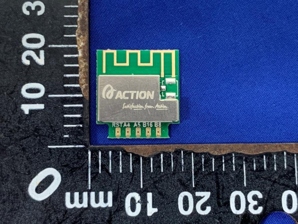
ATI-AW01
Sep 20, 2020802.11b/g/n Wi-Fi Module
Equipment Class
DTS - Digital Transmission System