ATI9R3VOH85128.5" LCD Monitor w/ FM Transmitter
Action Electronics Co.,Ltd.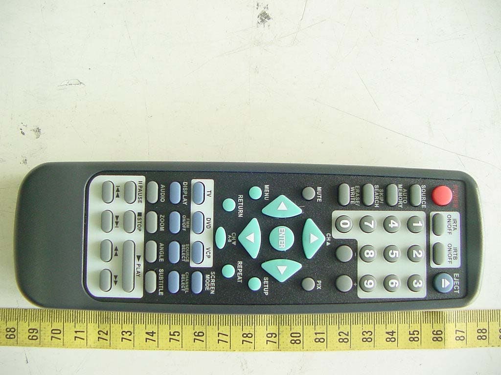
Click to zoom
Application Details
- Equipment Class
- DXX - Part 15 Low Power Communication Device Transmitter
- Date of Grant
- Feb 03, 2005
- Application Purpose
- Original Equipment
- Date of Application
- Feb 03, 2005
- Equipment Note
- 8.5" LCD Monitor w/ FM Transmitter
- Frequency Range
- 88.10000000 - 88.90000000
- Company
- Action Electronics Co.,Ltd.
- Country
- Malaysia
Documents & Files
Document Text
Text extracted from the exhibit documents filed with the FCC. Open a document above to read the original.
Users Manual
ELECTRONICS CORP . ® VOH8512 DROP-DOWN VIDEO MONITOR 128-7297 - 2 - Important Notice An LCD panel and/or video monitor may be installed in a motor vehicle and visible to the driver if the LCD panel or video monit or is used for vehicle information, system control, rear or side observation or navigation. If the LCD panel or video monitor is used for television reception, video or DVD play, the LCD panel or video monitor must be installed so that these features will only function when t he vehicle is in “park” or when the vehicle’s parking brake is applied.An LCD panel or video monitor used for television reception, video or DVD play that operates when the vehicle is in gear or whe n the parking brake is not applied must be installed to the rear of the driver’s seat where it will not be visible, directly or indir ectly, to the operator of the motor vehicle. Warnings Do not use any solvents or cleaning materials when cleaning the video monitor . Do not use any abrasive cleaners, they may scratch the screen. Use only a lightly dampened lint free cloth to wipe the screen if it is dirty. Lock the LCD screen in the fully closed position when not in use.Before putting on headphones always adjust the volume setting to the lowest position.Remember to leave the dome light switch in the off or auto positions when the vehicle is unattended, as the dome lights, if lef t on, can drain the vehicle’s battery.Do not put pressure on the screen.Caution children to avoid touching or scratching the screen, as it may become dirty or damaged. Television Reception This entertainment system is designed primarily for viewing prerecorded movies or playing video games. T elevision reception in a moving vehicle will be limited and in some areas will not be possible due to weak and variable signal strength. T elevision viewing in a stationary vehicle will result in an improvement, but may still be marginal due to signal strength. The quality of the picture will not b e consistent with home TV reception. Reception may be affected by weather and distance from TV station. A weak signal may cause the picture to roll, be snowy, or cause some color loss. Notice : The changes or modifications not expressly approved by the party responsible for compliance could void the user’s authority to operate the equipment. - 4 - Controls and Indicators Diagram 1 23 456789 101112 4 13 14 - 5 - Control Function Descriptions1. Infrared Transmitter and Sensor – Use to transmit audio to the wireless headphones. Also allows the remote controlto operate the VOH8512 and to control other accessories inthe system. 2. POWER Button – Used to turn the system ON/OFF. Bright red when system is on, dim when off. 3. Three position Dome Light Switch • Auto – Automatically switches on the dome lights in conjunction with the vehicle’s interior illumination. • Off – The dome lights will not turn on in this position. • On – Turns on the dome lights.4. Dome Lights – Provide additional interior illumination. 5. ( – ) Button – Picture quality adjustment (decrease). 6. ( + ) Button – Picture quality adjustment (increase). 7. PICTURE SELECT Button – Display picture adjustment mode (Brightness, Contrast, Color & Tint) 8. Screen Release – Moves in direction of the arrow to release the drop down screen. 9. Drop Down LCD Panel 10. IRT ON/OFF – Turn Infrared Transmitter power On/Off. 11. FM Select Button – When this button is pressed it will turn on the wireless FM Modulator and then cycle through FMfrequencies (FM Off, Channel 1, 88.3MHz; Channel 2,88.7MHz; Channel 3, 89.1MHz; Channel 4, 89.5MHz;Channel 5, 89.9MHz). 12. SOURCE Select – Used to select one of the three sources (AV1, AV2 ,AUX) 13. AUX – AUX input jack. 14. REAR Remote Sensor Eye – Allows the remote control to operate the VOH8512, and control other accessories,connected to the system. - 6 - Battery InstallationBefore attempting to operate your Remote Control, install thebatteries as described below. 1) Turn the Remote Control face down. Using a fingernail, lift the battery cover off. 2) Install two “AAA” batteries as shown. Make sure that proper polarity (+ or -) is observed. 3) Align the cover tabs with the remote control and press down until the cover clicks. The remote control will operate the VOH8512 and most AudiovoxVCP’s. It is not a universal remote control and will not controlequipment from other manufacturers.Remote Control Operation IRTA IRTB 123457689 10 11 12131415161718192021 232224252627282930313234333536373839404142 BATTERY COVER - 7 - Remote Control Function Descriptions *Function control is available on the unit and the remote control. ** Not used in this model*** Function only available if optional TV Tuner is installed. 1. POWER Button* Press this button to turn the VOH8512 on. Press the button again to turn the VOH8512 off. 2. SOURCE Button* Each time the button is pressed, the audio / video source will change: AV1, AV2, AUX. 3. AUTO MEMORY Button (AUTO PROGRAM Button) *** When the AUTO MEMORY button is pressed, all channels are searched and channels that are detected with signals ofsufficent levels are automatically stored. 4. SKIP/SEARCH Button *** This button selects betweeen SKIP and SEARCH mode. In “SKIP mode” the TV tuner will tune and stop on channels that areprogrammed into memory the when CHANNEL UP/DOWN buttons are used. When the SKIP mode is disabled, the TV willstop on all active channels. 5. ERASE/WRITE Button *** While tuned to a channel, pressing this button will store or erase the channel from memory . The stored channel numbers are displayed in “GREEN” and the erased channel numbers are displayed in “RED”. 6. Channel Up ( ) Button *** Use this button to increase the channel number to the desired channel and to scroll upward in menu options. - 8 - 7. MUTE Button Press this button to mute the audio.Pressing the button again restores the sound to the previously set level. 8. ENTER Button ** Used to implement a selected setting or menu option. 9. LEFT ( ) Button** Allows …
Text truncated - open the document above for the full version.
Users Manual
Installation Guide ® ELECTRONICS CORP . VOH8512 DROP-DOWN VIDEO MONITOR Important Notice An LCD panel and/or video monitor may be installed in a motor vehicle and visible to the driver if the LCD panel or video monitor is used for vehicle information, system control, rear or side observation or navigation. If the LCD panel or video monitor is used for television reception, video or DVD play, the LCD panel or video monitor must be installed so that these features will only function when the vehicle is in “park” or when the vehicle’s parking brake is applied. An LCD panel or video monitor used for television reception, video or DVD play that operates when the vehicle is in gear or when the parking brake is not applied must be installed to the rear of the driver’s seat where it will not be visible, directly or indirectly, to the operator of the motor vehicle. MATERIALS INCLUDED IN THIS PACKAGE: 1)VOH8512 Video Monitor (P/N 136-3904) – 1pc 2)Trim Ring (P/N 102-4088) – 1pc 3) Remote Control (P/N 136-3855) – 1pc 4) Hardware Package:- • #4 x 3/8" Screws – 9pcs • #8 x 5/8" Self Drilling Screws – 4pcs • #8 Washers – 4pcs 5) 2 Pin Power Wire Harness with choke (P/N 112B3143) – 1pc 6) 12 Pin Power Harness (P/N 112-3483) – 1pc 7) Accessory Harness (P/N 8010730) – 1pc 8) A/V Adapter Cable (P/N 112B3227) – 1pc 9) PODTVT TV Tuner (P/N 136-3877) – 1pc (optional) 10) SIRSWB Relay Box (P/N 112C3159) – 1pc (optional) -1- TOOLS REQUIRED: #2 Phillips Screwdriver #1 Phillips Screwdriver Utility or Razor Knife or Shears Wire Strippers Upholstery hook tool (for removal of panels as necessary) Electrical Tape Masking Tape Multimeter (to verify 12 volt DC and continuity: Do not use a test light or logic probe) Marker pen – to mark headliner Scribe (to mark trim ring if used) Misc. electrical connectors (to connect to vehicle power source). Requirements will vary from vehicle to vehicle) (Optional) (Optional) 1.2.3.4. 5.6. 7. 8. 9. 10. GENERAL INSTALLATION APPROACH: 1)Decide upon system configuration and options that will be installed (i.e.: what components, VCP, Video Game, external amp, wireless headphones, VCP, etc.). 2)Review all manuals to become familiar with electrical requirements and hook ups. 3)Decide upon mounting locations of all components and method of mounting. 4)Prep the vehicle by removing any interior trim necessary to gain access to vehicle's wiring as well as all areas where interconnecting wire harnesses will need to be located. If any access holes need to be cut into the vehicle (headliner, other trim components etc.), this should be done now as well. (Refer to Page 3). 5)Route the wiring harnesses throughout the vehicle as necessary. (Refer to the Wiring Diagrams on pages 6 of this manual as well as the wiring instructions for the individual components and accessory options being installed). Be sure that all wiring is protected from sharp edges and is routed in such a manner that it will not be pinched when all components and interior trim are fully installed. Be sure to leave enough slack in the wiring at each component to allow working room. 6)Remove all A/V system components from their packaging and place them loosely in the vehicle at their respective locations. 7)Connect all components together (electrically) and verify proper operation of all system functions. Note: This is best done BEFORE, components have been permanently mounted. 8)After verifying proper operation of the system, proceed to mount of each component. 9)When all components are mounted, recheck function of entire system again to ensure that no wiring was pinched or connected improperly during final installation. GENERAL SYSTEM CONFIGURATIONS: The following is intended to provide some of the system configurations that are possible with the VOH8512 series Drop Down Video Systems: -2- Notes : There are a few audio output options that can be added as follows: a) Wireless Headphones (P/N MVIRHS). b) Wired relay box for wireless FM Modulator. The VOH8512 video systems are only intended for an overhead, drop down installation. It is not intended for Seatback or any other type of mounting. The hinging mechanism is designed for horizontal, drop down use only. VEHICLE PREPARATION: 1)Locate an accessory power source (+12v when key is in the ACC. and run positions, and 0v when key is off), and also a good ground generally, these wires can be found at the ignition switch or fuse-box. 2)The mounting method and location will vary from vehicle to vehicle, so this manual will only focus on the installation of the video monitor and related console accessories. 3)Generally, the best location for the video monitor is where the vehicle's factory dome light is in- stalled. The monitor should be located in such a manner that it can be comfortably viewed by rear seat passengers. NEVER INSTALL THE MONITOR IN A PLACE WITHIN THE DRIVER'S VIEW. THIS IS NOT ONLY DANGEROUS, BUT IT IS ALSO ILLEGAL IN MANY STATES. 4)Once the mounting location of the monitor has been determined, there may be additional prepara- tion work necessary, depending on the vehicle structure and installation method. Some of the steps that may be required are: A) Removal of the vehicle's dome light B) The headliner may need to be trimmed. -3- MINI CONSOLE INSTALLATION: This page only covers special installation considerations for the mini-console installation. If the video monitor is to be installed in a vehicle with the mini console, this console may need to be trimmed to fit the contour of the vehicle headliner. 1)In this installation, the video monitor is mounted directly to the overhead cross-member in the roof using the mounting screw bosses. These screw bosses should contact the cross-member di- rectly (i.e.: no gap between the screw boss and the roof structure). Also, be sure that the screws do not pierce the outer roof skin when fully fastened to the cross-member. The mini-console is attached to the video monitor using the perimeter screw bosses. It is important that the …
Text truncated - open the document above for the full version.
Cover Letter(s)
1 Helen Zhao Subject:FW: ACTION ELECTRONICS CO., LTD., FCC ID: ATI9R3VOH8512, Assessment NO.: AN05T4479, Notice#1 Exhibit-F-Test_Setu p_Photo-1.p... From: SS Sent: Wednesday, February 02, 2005 6:33 PM To: Helen Zhao Cc: R00/??? Subject: Re: ACTION ELECTRONICS CO., LTD., FCC ID: ATI9R3VOH8512, Assessment NO.: AN05T4479, Notice#1 Dear Helen, The EUT was placed on the table just like you plotted. This device is not heavy and it can stand up with the supporting of signal cables. Please refer to the setup photos, the signal cables successfully support the EUT and keep it steady. Best regards, S. S. Liou > Dear SS, > > Regarding Q2: It seems you simulated the normal condition when the EUT is > installed in the car. Please refer to the attachment and confirm whether > the EUT was placed like this during the test. If the answer is YES, please > advise how you make it stable on the table. If the answer is NO, please > illustrate how the EUT was placed. > > Thank you, > Helen > > -----Original Message----- > From: SS > Sent: Wednesday, February 02, 2005 1:07 AM > To: Helen Zhao > Cc: R00/??? > Subject: Re: ACTION ELECTRONICS CO., LTD., FCC ID: ATI9R3VOH8512, > Assessment NO.: AN05T4479, Notice#1 > > > Dear Helen, > > Replying your questions. > > #1 A 1kHz audio signal was input to the EUT. Please refer to section 1.3 of > the revised test report. > #2 Please refer to attached additional product photos. > #3 Please refer to attached installation guide. 2 > > Best regards, > > S. S. Liou >> > -----Original Message----- > From: Compliance Certification Services [mailto:[email protected]] > Sent: Friday, January 21, 2005 4:57 PM > To: Helen Zhao > Subject: ACTION ELECTRONICS CO., LTD., FCC ID: ATI9R3VOH8512, Assessment > NO.: AN05T4479, Notice#1 > > > Question #1: The test report does not show that bandwidth test was done with > maximum input signal and user controls adjusted to maximize emission. Please > confirm if the test was done correctly following FCC requirements. > > Question #2: Please provide more external photos of the EUT, top view, > bottom view, side view. The EUT shown on setup photos looks different from > that on the external photos. > > Question #3: Is device mounted on the inner-roof of the vehicle? The photo > on FCC ID label exhibit suggests this. There are no enough external photos, > no installation guide in the user manual provided in the filing to make a > firm determination. Please resubmit user manual to provide more detailed > information. > > Best Regards, > Helen Zhao > > The items indicated above must be submitted before processing can continue > on the above referenced application. Failure to provide the requested > information within 30 days of the original e-mail date may result in > application dismissal and forfeiture of the filing fee. Also, please note > that partial responses increase processing time and should not be submitted. > Any questions about the content of this correspondence should be directed to > the e-mail address listed below the name of the sender. > >
External Photos
ETC Report No.:ET93R-12-020-02 Sheet 1 of 10 Sheets FCC ID.: ATI9R3VOH8512 Rev. No 1.0 CONSTRUCTED PHOTOS of EUT A. 8.5” LCD MONITOR 1. Open View of EUT 2. Rear View of EUT ETC Report No.:ET93R-12-020-02 Sheet 8 of 10 Sheets FCC ID.: ATI9R3VOH8512 Rev. No 1.0 CONSTRUCTED PHOTOS of EUT B. Remote Control 1. Front View of Remote Control 2. Rear View of Remote Control
ID Label/Location Info
Model: VOH8512 FCC ID: ATI9R3VOH8512 This device complies with FCC Rules Part 15. Operation is subject to the following two conditions : (1) This device may not cause harmful interference and (2) This device must accept any interference that may be received, including interference that may cause undesired operation. 70mm 60mm
Internal Photos
ETC Report No.:ET93R-12-020-02 Sheet 2 of 10 Sheets FCC ID.: ATI9R3VOH8512 Rev. No 1.0 CONSTRUCTED PHOTOS of EUT 3. Intrernal View of EUT 4. Internal View of EUT ETC Report No.:ET93R-12-020-02 Sheet 3 of 10 Sheets FCC ID.: ATI9R3VOH8512 Rev. No 1.0 CONSTRUCTED PHOTOS of EUT 5. Component View of PCB 6. Solder View of PCB ETC Report No.:ET93R-12-020-02 Sheet 4 of 10 Sheets FCC ID.: ATI9R3VOH8512 Rev. No 1.0 CONSTRUCTED PHOTOS of EUT 7. Component View of PCB 8. Solder View of PCB ETC Report No.:ET93R-12-020-02 Sheet 5 of 10 Sheets FCC ID.: ATI9R3VOH8512 Rev. No 1.0 CONSTRUCTED PHOTOS of EUT 9. Component View of PCB 10. Solder View of PCB ETC Report No.:ET93R-12-020-02 Sheet 6 of 10 Sheets FCC ID.: ATI9R3VOH8512 Rev. No 1.0 CONSTRUCTED PHOTOS of EUT 11. Component View of PCB 12. Solder View of PCB ETC Report No.:ET93R-12-020-02 Sheet 7 of 10 Sheets FCC ID.: ATI9R3VOH8512 Rev. No 1.0 CONSTRUCTED PHOTOS of EUT 13. Component View of PCB 14. Solder View of PCB ETC Report No.:ET93R-12-020-02 Sheet 9 of 10 Sheets FCC ID.: ATI9R3VOH8512 Rev. No 1.0 CONSTRUCTED PHOTOS of EUT 3. Internal View of Remote Control PCB ETC Report No.:ET93R-12-020-02 Sheet 10 of 10 Sheets FCC ID.: ATI9R3VOH8512 Rev. No 1.0 CONSTRUCTED PHOTOS of EUT 4. Component View of Remote Control PCB 5. Solder View of Remote Control PCB
Test Report
Rev. No 1.0 FCC Part 15 Subpart C TEST REPORT of E.U.T. : 8.5” LCD MONITOR FCC ID. : ATI9R3VOH8512 MODEL : VOH8512;OHM80852 Working Frequency : 88.3~89.9 MHz for APPLICANT : ACTION ELECTRONICS CO., LTD. ADDRESS : 198, Chung Yuan Rd., Chung Li Ind. Zone Chung Li, Tao Yuan Hsien, Taiwan, R.O.C. Test Performed by ELECTRONICS TESTING CENTER, TAIWAN NO. 34, LIN 5, DING FU TSUN, LINKOU HSIANG, TAIPEI HSIEN, TAIWAN, R.O.C. http://www.etc.org.tw ; e-mail : [email protected] Tel:(02)26023052 Fax:(02)26010910 Report Number : ET93R-12-020-02 ETC Report No.:ET93R-12-020-02 FCC ID.: ATI9R3VOH8512 Rev. No 1.0 TEST REPORT CERTIFICATION Applicant : ACTION ELECTRONICS CO., LTD. 198, Chung Yuan Rd., Chung Li Ind. Zone Chung Li, Tao Yuan Hsien, Taiwan, R.O.C. Manufacture : ACTION INDUSTRIES (M) SDN BHD. 2480 TINGKAT PERUSAHAAN ENAM, PRAI FREE TRADE ZONE, 13600 PERAI, PENANG, MALAYSIA Description of EUT : a) Type of EUT : 8.5” LCD MONITOR b) Trade Name : AUDIOVOX c) Model No : VOH8512;OHM80852 (ACTION) d) Working Frequency : 88.3~89.9 MHz e ) Power Supply : DC 12V Regulation Applied : FCC Rules and Regulations Part 15 Subpart C (2003) I HEREBY CERTIFY THAT; The data shown in this report were made in accordance with the procedures given in ANSI C63.4 and the energy emitted by the device was founded to be within the limits applicable. I assume full responsibility for accuracy and completeness of these data. Issued Date : Dec. 28, 2004 Test Engineer : ( Bo-Sen Fu ) Approve & Authorized Signer : Will Yauo, Manager EMC Dept. II of ELECTRONICS TESTING CENTER, TAIWAN ETC Report No.:ET93R-12-020-02 FCC ID.: ATI9R3VOH8512 Rev. No 1.0 Table of Contents Page 1. GENERAL INFORMATION..................................................................................................1 1.1 Product Description...........................................................................................................1 1.2 Characteristics of Device:................................................................................................1 1.3 Test Methodology..............................................................................................................1 1.4 Test Facility.........................................................................................................................1 2. DEFINITION AND LIMITS....................................................................................................2 2.1 Definition.............................................................................................................................2 2.2 Restricted Bands of Operation........................................................................................2 2.3 Limitation.............................................................................................................................2 2.4 Labeling Requirement.......................................................................................................3 2.5 User Information................................................................................................................3 3. SYSTEM TEST CONFIGURATION.....................................................................................4 3.1 Justification..........................................................................................................................4 3.2 Devices for Tested System..............................................................................................4 4 RADIATED EMISSION MEASUREMENT..........................................................................5 4.1 Applicable Standard..........................................................................................................5 4.2 Measurement Procedure...................................................................................................5 4.3 Measuring Instrument.......................................................................................................7 4.4 Test Data...............................................................................................................................8 4.4.1 Fundamental and Harmonics.........................................................................................................................8 4.4.2 Other Emissions............................................................................................................................................10 4.5 Field Strength Calculation.............................................................................................10 4.6 Radiated Measurement Photos.....................................................................................11 5 CONDUCTED EMISSION MEASUREMENT...................................................................12 5.1 Standard Applicable...............................................................................................................12 6 ANTENNA REQUIREMENT...............................................................................................13 6.1 Standard Applicable........................................................................................................13 6.2 Antenna Construction.....................................................................................................13 7 EMISSION BAND MEASUREMENT..................................................................................14 7.1 Standard Applicable........................................................................................................14 7.2 Measurement Procedure.................................................................................................14 7.3 Measurement Equipment...............................................................................................14 7.4 Measurement Data...........................................................................................................14 APPENDIX 1 : PLOTTED DATA FOR EMISSION BAND MEASUREMENT.................15 ETC R…
Text truncated - open the document above for the full version.
Test Setup Photos
ETC Report No.:ET93R-12-020-02 Sheet 11 of 19 Sheets FCC ID.: ATI9R3VOH8512 Rev. No 1.0 4.6 Radiated Measurement Photos
Contact Information
Applicant
L.L TAN(Asst. Manager)
Test Firm
Electronics Testing Center, TaiwanWill Yauo
Technical Specifications
| # | Rule Parts | Frequency Range | Power Output |
|---|---|---|---|
| 1 | 15C | 88.1 MHz - 88.9 MHz | - |
Other Applications from Action Electronics Co.,Ltd.
ATI47789071001
Jan 22, 2026ClubCarSync
Equipment Class
DTS - Digital Transmission SystemATI9R3SB11MD1
Dec 25, 202511.6 IN-CAR SEATBACK MONITOR WITH DVD + 11.6 IN-CAR SEATBACK MONITOR
Equipment Class
DTS - Digital Transmission SystemATI9R3SB11M1
Dec 25, 202511.6 IN-CAR SEATBACK MONITOR WITH DVD + 11.6 IN-CAR SEATBACK MONITOR
Equipment Class
DTS - Digital Transmission SystemATI9R3103759
Dec 24, 2025Bluetooth Headphones
Equipment Class
DSS - Part 15 Spread Spectrum Transmitter
ATI-AW01
Sep 20, 2020802.11b/g/n Wi-Fi Module
Equipment Class
DTS - Digital Transmission System