AUSCR7022ASLOANE SHELF SYSTEM
Modern Marketing Concepts, Inc.
Click to zoom
Application Details
- Equipment Class
- DSS - Part 15 Spread Spectrum Transmitter
- Date of Grant
- Nov 08, 2022
- Application Purpose
- Original Equipment
- Date of Application
- Nov 08, 2022
- Equipment Note
- SLOANE SHELF SYSTEM
- Frequency Range
- 2402.00000000 - 2480.00000000
- Country
- United States
Documents & Files
Document Text
Text extracted from the exhibit documents filed with the FCC. Open a document above to read the original.
Users Manual
CR7022A-BK Vinyl Turntables with external Speaker - USER MANUAL - Product Description 1. Turntable Platter 2. Turutable Shaft 3. Tonearm 4. Tonearm Lever 5. Auto-stop Switch 6. Speed Switch 7. Hold Down Clip 8. 45 RPM Adaptor General Operation Essential Setup 1. Connect the Left and Right speakers to OUT-L/OUT-R jacks at the back of the unit. 2. Place the speakers on a flat and level surface. The selected location should be stable and free from vibration. 3. Remove the tie-wrap that is holding the tonearm. 4. Plug the power cord to unit firstly and then plug the adapter to wall power outlet. 5. Hold and press the “ /MODE” button to turn on the unit. And short press the “ /MODE” button to select the desired mode. Bluetooth In Operation 9. AUX IN Jack 10. Power/Mode Button 11. USB Port 12. Previous Section/ Previous Station 13. Record Button 14. Next Section/Next Station 15. Play/Pause 16. Volume Knob 17. LED Display 18. Left/Right Speaker Jack 19. FM Antenna 20. Audio Output Jack 21. Power Input Jack 1. Press “ /MODE” key to change to Bluetooth pairing mode, the LED display will show “bt”. 2. Turn on the Bluetooth feature of your audio device, search for “CROSLEY CR7022A” and pair. 3. Once your device is successfully connected with the speakers, you will hear a short confirmation sound from the speakers. 4. Play and stream music from your device to the speakers. Hold and press the “Play/Pause” key to disconnect the Bluetooth connection. AUX IN Operation Press “ /MODE” key to change to AUX IN mode, the LED display will show “AUX”. Connect one end of a 3.5 mm audio cable(not supplied) to speaker’s AUX INPUT jack, then connect the other end to the output jack of your audio device(such as Mobile phone/MP3 Player). Turntable Operation 1. Press “ /MODE” key to change to PHONO mode, the LED display will show “PHON” 2. Select the desired speed(331/3, 45, 78) and place the record on the platter. (Remark: When playing a 45 RPM record, please use the 45 RPM adapter.) 3. Remove the stylus protector from the stylus. Release the tone arm from the tone arm clip. 4. Use the tonearm lever to raise the tonearm. Move the tonearm gently to desired position over the record. Push the lift lever again to descend the tonearm slowly onto the desired position on the record to start playing. 5. When the record is finished playback, push the tonearm lever again to lift up the tonearm. And return the tonearm to the arm rest. Use the tonearm lever to descend the tonearm. Remark: -When the Auto stop switch is “ON”, the record will stop automatically when finished. When the Auto stop switch is “OFF”, the record will not stop automatically when finished. -Do not touch the stylus tip by fingers. FM mode When you switch the unit to the radio mode, you can listen to the FM radio program in this mode. 1.This radio antenna is on the back of the machine. When you need to listen to radio, please open the FM antenna. 2.In FM mode, hold and press the Play/Pause key on the unit to automatically search station. It will save the station once searching completed. 3.Press the “” or “” to select station. Bluetooth Out Operation This function can transmit the record playing on the unit to external Bluetooth speaker/headphone by Bluetooth wireless connection. 1. Press “ /MODE” key to change to Bluetooth Out function, the LED display will show “bt-O” and flashing. 1. Turn on the external Bluetooth receiver device (i.e Bluetooth Speaker or Bluetooth Headphone) and entering the pairing mode. 2. The turntable unit and external Bluetooth receiver will connect automatically. This process can take up to approx. 30-45 seconds. (Remark: Place the Bluetooth receiver device within 1m of the unit to connect properly.) 3. Once turntable unit is successfully connected with the external Bluetooth speakers, you will hear a short confirmation sound from the speakers and the word “bt-O” in the display will be solid. 4. Select the desired speed(33 1/3, 45, 78) and place the record on the platter. The music will be heard from the external Bluetooth speaker/headphone. Remark: “Bluetooth Out” only work with record playback. “Bluetooth Out” cannot work in Bluetooth IN/ Aux In/FM/ USB function. Record Operation 1. You can record the playing music from phono record is playing in the USB flash stick 2. Insert a USB flash stick to the USB port 3. Short press the REC key during the phono record is playing. 4. Short Press REC key again to stop the recording and replay the recorded track 5. To delete the recorded track, long press the REC key during it is playing Audio Out Operation The audio Jacks output analog line-level signals and could be connected directly with a pair of active/powered speakers or the appropriate input of your stereo system. Note: 1. The Audio Jacks are not designed to be connected directly to the passive/unpowered speakers. If connected to the passive speakers, the volume level will be very low. 2. If want to mute the unit, please hold and press the “” button to mute the unit or unplug the speakers from Out L/R jack. Trouble Shooting NOTE: This equipment has been tested and found to comply with the limits for a Class B digital device, pursuant to part 15 of the FCC Rules. These limits are designed to provide reasonable protection against harmful interference in a residential installation. This equipment generates uses and can radiate radio frequency energy and, if not installed and used in accordance with the instructions, may cause harmful interference to radio communications. However, there is no guarantee that interference will not occur in a particular installation. If this equipment does cause harmful interference to radio or television reception, which can be determined by turning the equipment off and on, the user is encouraged to try to correct the interference by one or more of the following measures: - Reorient or relocate the receiving antenna. - Increase the separation between the equipment and receiver. -Connect the equipment into…
Text truncated - open the document above for the full version.
Cover Letter(s)
Modern Marketing Concepts, Inc 1220 E Oak, St. Louisville, Kentucky, United States 40204 Agent Authorization Company: Modern Marketing Concepts, Inc Address: 1220 E Oak, St. Louisville, Kentucky, United States 40204 Product Name: SLOANE SHELF SYSTEM Model Number(s): CR7022A, CR7022A-BK, CR7022X-XX(X-XX can be replaced by letter from "A" to "Z" or number from "0" to "9" or blank. YQ-984T-B), YQ-XXXX- X(XXXX-X can be by letter from "A" to "Z" or number from "0" to "9" or blank) Product Description: SLOANE SHELF SYSTEM We authorize MiCOM Labs Inc., 575 Boulder Court, Pleasanton, California 94566, USA, to act on our behalf on all matters concerning the certification of above named equipment. We declare that MiCOM Labs Inc. is allowed to forward all information related to the approval and certification of equipment to the regulatory agencies as required and to discuss any issues concerning the approval application. Any and all acts carried out by MiCOM Labs on our behalf shall have the same effect as acts of our own. Signature: Date: Sep. 15, 2022 Name: Scott McWhorter Title: Director of Engineering Company: Modern Marketing Concepts, Inc
Cover Letter(s)
Modern Marketing Concepts, Inc 1220 E Oak, St. Louisville, Kentucky, United States 40204 Sep. 15, 2022 Office of Engineering Technology Federal Communications Commission 7435 Oakland Mills Road Columbia, MD 21046 USA Subject: Explanation of differences between product types FCC ID: AUSCR7022A Models: CR7022A, CR7022A-BK, CR7022X-XX(X-XX can be replaced by letter from "A" to "Z" or number from "0" to "9" or blank. YQ-984T-B), YQ-XXXX-X(XXXX-X can be by letter from "A" to "Z" or number from "0" to "9" or blank) To Whom It May Concern: We, The Modern Marketing Concepts, Inc. hereby declare that the model : CR7022A is identical with the model : CR7022A-BK, CR7022X-XX(X-XX can be replaced by letter from "A" to "Z" or number from "0" to "9" or blank. YQ-984T-B), YQ-XXXX-X(XXXX-X can be by letter from "A" to "Z" or number from "0" to "9" or blank), except the model names and the color of appearance. Except for the different above, no other modification is performed. Sincerely, Modern Marketing Concepts, Inc. Signature: [Scott McWhorter, General Manager]
Cover Letter(s)
Modern Marketing Concepts, Inc. 1220 E Oak, St. Louisville, Kentucky, United States 40204 Office of Engineering Technology Federal Communications Commission 7435 Oakland Mills Road Columbia, MD 21046 USA Date: Sep. 15, 2022 Subject; Request for Confidentiality FCC ID: AUSCR7022A To Whom It May Concern, Pursuant to the provisions of the Commission’s rules Title 47 Sections §0.457 and §0.459, we are requesting the Commission to withhold the following attachment(s) as confidential documents from public disclosure indefinitely. These documents contain detailed system and equipment descriptions and are considered as proprietary information in operation of the equipment. The public disclosure of these documents might be harmful to our company and would give competitors an unfair advantage in the market. Schematic Diagram Block Diagram Operational Description Parts List It is our understanding that all measurement test reports, FCC ID label format and correspondence during the certification review process cannot be granted as confidential documents and this information will be available for public review once the grant of equipment authorization is issued. Sincerely, Signature: Name: Scott McWhorter Title: Director of Engineering
External Photos
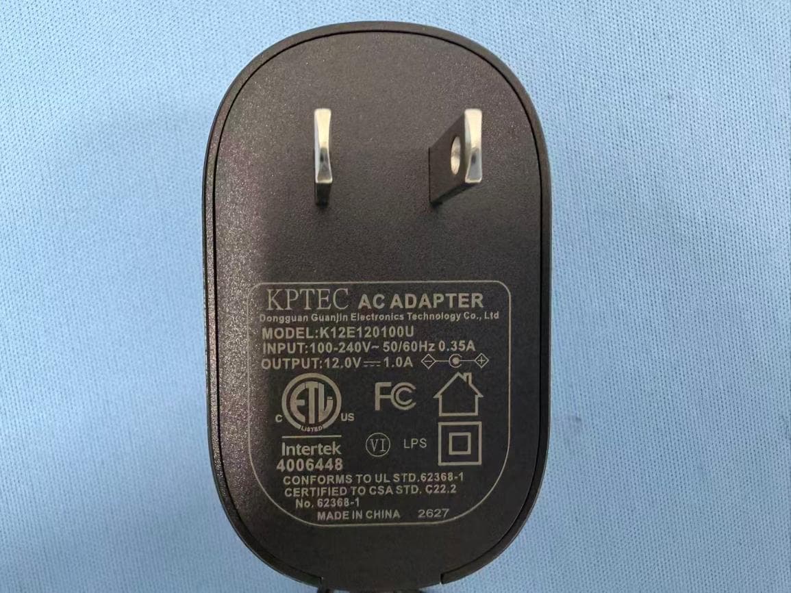
Report No.: AGC06815220802AP02 Page 1 of 4 EXTERNAL PHOTOS All VIEW OF EUT ADAPTER VIEW OF EUT Report No.: AGC06815220802AP02 Page 2 of 4 TOP VIEW OF EUT BOTTOM VIEW OF EUT Report No.: AGC06815220802AP02 Page 3 of 4 FRONT VIEW OF EUT BACK VIEW OF EUT Report No.: AGC06815220802AP02 Page 4 of 4 LEFT VIEW OF EUT RIGHT VIEW OF EUT ****************************************End of Report****************************************
ID Label/Location Info
FCC ID Label Location 30mm*20mm FCC ID: AUSCR7022A This device complies with Part 15 of the FCC Rules. Operation is subject to the following two conditions: (1) this device may not cause harmful interference, and (2) this device must accept any interference received, including interference that may cause undesired operation.
Internal Photos
Report No.: AGC06815220802AP02 Page 1 of 5 INTERNAL PHOTOS OPEN VIEW OF EUT (FIGURE 1) OPEN VIEW OF EUT (FIGURE 2) Report No.: AGC06815220802AP02 Page 2 of 5 ANTENNA CLOSE-UP PHOTO-1 INTERNAL VIEW OF EUT (FIGURE 1) Antenna Report No.: AGC06815220802AP02 Page 3 of 5 INTERNAL VIEW OF EUT (FIGURE 2) INTERNAL VIEW OF EUT (FIGURE 3) Report No.: AGC06815220802AP02 Page 4 of 5 INTERNAL VIEW OF EUT (FIGURE 4) INTERNAL VIEW OF EUT (FIGURE 5) Report No.: AGC06815220802AP02 Page 5 of 5 INTERNAL VIEW OF EUT (FIGURE 6) ****************************************End of Report****************************************
RF Exposure Info
RF EXPOSURE EVALUATION 1. PRODUCT INFORMATION Product Description SLOANE SHELF SYSTEM Test Model CR7022A Series Model CR7022A-BK, CR7022X-XX(X-XX can be replaced by letter from "A" to "Z" or number from "0" to "9" or blank. YQ-984T-B), YQ-XXXX-X(XXXX-X can be by letter from "A" to "Z" or number from "0" to "9" or blank) FCC ID AUSCR7022A 2. EVALUATION METHOD According to 447498 D01 General RF Exposure Guidance v06 The 1-g and 10-g SAR test exclusion thresholds for 100 MHz to 6 GHz at test separation distances ≤ 50 mm are determined by: [(max. power of channel, including tune-up tolerance, mW)/(min. test separation distance, mm)] ·[√f(GHz)] ≤ 3.0 for 1-g SAR and ≤ 7.5 for 10-g extremity SAR. Where f(GHz) is the RF channel transmit frequency in GHz Power and distance are rounded to the nearest mW and mm before calculation 3. CALCULATION BR/EDR: Pt=-6.234dBm=0.238mW The value of the Maximum output power Pt is referred to the test report of the CFR47 §15.247. The result for RF exposure evaluation SAR=(0.238mW /5mm) .[√2.402(GHz)]= 0.07<3.0 for 1-g SAR and ≤ 7.5 for 10-g extremity SAR. 4. CONCLUSION The SAR evaluation is not required.
Test Report
Product specification Quick Reference Date Antenna module on the system board Frequenc Range2400 ~ 2500MHz Ant. Port Input Pwr. (dBm)0 (Typ. BT class 2 output power) Tot. Rad. Pwr. (dBm)-1.2 (Input pwr – loss pwr) Peak EIRP(dBm)1.2 Directivity (dBi)1 (all direction antenna) Efficiency (dB)6 0.2 % Gain (dBi)1.2 (Avg Gain XY-plane) Maximum Power (dBm)1.7 (XY-plane) Minimum Power (dBm)-4(XY-plane) Avg. Power (dBm)-0.5(XY-plane) Input Impendence(ohm)50 Polarization TypeV ertical & Horizontal V . S .W . R< 1.4 All the technical data and information contained herein are subject to change without prior notice Antenna Layout & module on the system board Antenna Gain Gain Table Unit in dBi @2.44GHz XY-plane XZ-plane YZ-plane Efficiency Peak Avg. Peak Avg. Peak Avg. Module Board 1.2-0.5-3.61.1-3.06 0.2 % 1.2 ANT-01 ZHUHAI YALI TECHNOLOGY CO.,LTD 14.5mm*3.9mm RetumLoss TheEnvironmentofAntennaRadiationPattem 3Dradiationpatterndiagram XY-planeXZ-planeYZ-plane
Test Report
Page 1 of 69 FCC Test Report Report No.: AGC06815220802FE03 FCC ID : AUSCR7022A APPLICATION PURPOSE : Original Equipment PRODUCT DESIGNATION : SLOANE SHELF SYSTEM BRAND NAME : CROSLEY MODEL NAME : CR7022A, CR7022A-BK, CR7022X-XX(X-XX can be replaced by letter from "A" to "Z" or number from "0" to "9" or blank. YQ-984T-B), YQ-XXXX-X(XXXX-X can be by letter from "A" to "Z" or number from "0" to "9" or blank) APPLICANT : Modern Marketing Concepts, Inc. DATE OF ISSUE : Sep. 15, 2022 STANDARD(S) : FCC Part 15.247 REPORT VERSION : V1.0 Attestation of Global Compliance (Shenzhen) Co., Ltd Report No.: AGC06815220802FE03 Page 2 of 69 REPORT REVISE RECORD Report Version Revise Time Issued Date Valid Version Notes V1.0 / Sep. 15, 2022 Valid Initial Release Report No.: AGC06815220802FE03 Page 3 of 69 TABLE OF CONTENTS 1. VERIFICATION OF CONFORMITY .................................................................................................................. 5 2. GENERAL INFORMATION .............................................................................................................................. 6 2.1. PRODUCT DESCRIPTION ........................................................................................................................ 6 2.2. TABLE OF CARRIER FREQUENCYS ....................................................................................................... 6 2.3. RECEIVER INPUT BANDWIDTH .............................................................................................................. 7 2.4. EXAMPLE OF A HOPPING SEQUENCY IN DATA MODE ......................................................................... 7 2.5. EQUALLY AVERAGE USE OF FREQUENCIES AND BEHAVIOUR ......................................................... 7 2.6. RELATED SUBMITTAL(S) / GRANT (S) .................................................................................................... 8 2.7. TEST METHODOLOGY ............................................................................................................................. 8 2.8. SPECIAL ACCESSORIES ......................................................................................................................... 8 2.9. EQUIPMENT MODIFICATIONS ................................................................................................................. 8 2.10. ANTENNA REQUIREMENT..................................................................................................................... 8 3. MEASUREMENT UNCERTAINTY ................................................................................................................... 9 4. DESCRIPTION OF TEST MODES ................................................................................................................. 10 5. SYSTEM TEST CONFIGURATION ................................................................................................................ 11 5.1. CONFIGURATION OF EUT SYSTEM ...................................................................................................... 11 5.2. EQUIPMENT USED IN TESTED SYSTEM .............................................................................................. 11 5.3. SUMMARY OF TEST RESULTS .............................................................................................................. 11 6. TEST FACILITY .............................................................................................................................................. 12 7. PEAK OUTPUT POWER ................................................................................................................................ 13 7.1. MEASUREMENT PROCEDURE ............................................................................................................. 13 7.2. TEST SET-UP (BLOCK DIAGRAM OF CONFIGURATION) .................................................................... 13 7.3. LIMITS AND MEASUREMENT RESULT .................................................................................................. 14 8. 20DB BANDWIDTH ........................................................................................................................................ 19 8.1. MEASUREMENT PROCEDURE ............................................................................................................. 19 8.2. TEST SET-UP (BLOCK DIAGRAM OF CONFIGURATION) .................................................................... 19 8.3. LIMITS AND MEASUREMENT RESULTS ............................................................................................... 20 9. CONDUCTED SPURIOUS EMISSION........................................................................................................... 25 9.1. MEASUREMENT PROCEDURE ............................................................................................................. 25 Report No.: AGC06815220802FE03 Page 4 of 69 9.2. TEST SET-UP (BLOCK DIAGRAM OF CONFIGURATION) .................................................................... 25 9.3. MEASUREMENT EQUIPMENT USED .................................................................................................... 25 9.4. LIMITS AND MEASUREMENT RESULT .................................................................................................. 25 10. RADIATED EMISSION ................................................................................................................................. 46 10.1. MEASUREMENT PROCEDURE ........................................................................................................... 46 10.2. TEST SETUP ......................................................................................................................................... 48 10.3. LIMITS AND MEASUREMENT RESULT ............................................................................................... 49 10.4. TEST RESULT......................................…
Text truncated - open the document above for the full version.
Test Setup Photos
Report No.: AGC06815220802AP01 Page 1 of 2 TEST SETUP PHOTOS RADIATED EMISSION TEST SETUP BELOW 1GHz RADIATED EMISSION TEST SETUP ABOVE 1GHz Report No.: AGC06815220802AP01 Page 2 of 2 AC POWER LINE CONDUCTED TEST SETUP RF CONDUCTED TEST SETUP ****************************************End of Report*************************************
Contact Information
Applicant
Scott McWhorter(Director of Engineering)
Technical Contact
Test Firm
Attestation of Global Compliance (Shenzhen) Co., LDoris Li
[email protected]+86-755-25234088
Technical Specifications
| # | Rule Parts | Frequency Range | Power Output |
|---|---|---|---|
| 1 | 15C | 2.40 GHz - 2.48 GHz | 200.00 µW |
Other Applications from Modern Marketing Concepts, Inc.
AUSCR31DV2
Sep 03, 2026COMPANION RADIO
Equipment Class
DSS - Part 15 Spread Spectrum Transmitter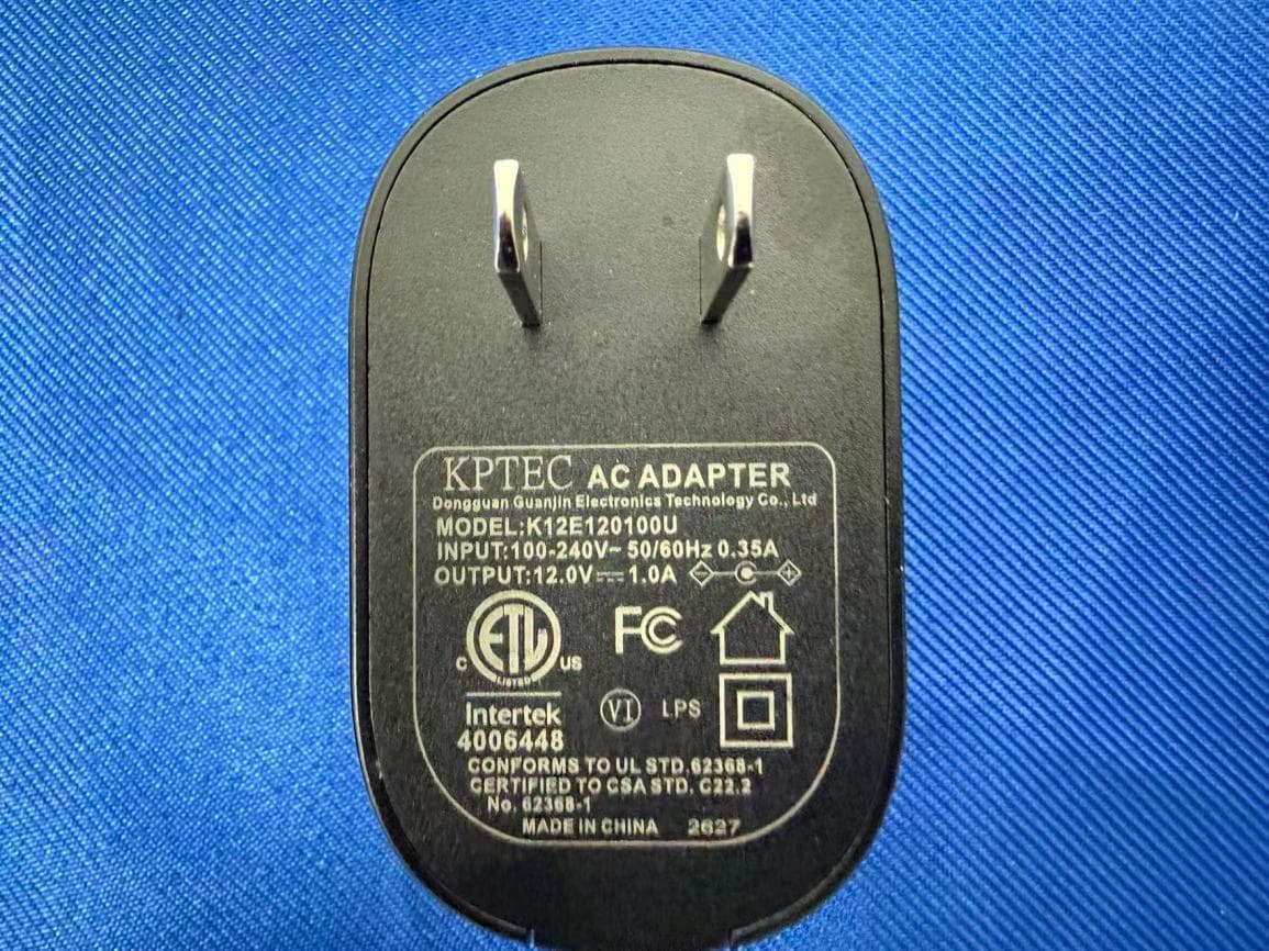
AUSCR32DV2
Sep 02, 2026CATHEDRAL RADIO CD PLAYER
Equipment Class
DSS - Part 15 Spread Spectrum TransmitterAUSCR3506A
Aug 11, 2026VIBE CD PLAYER
Equipment Class
DSS - Part 15 Spread Spectrum Transmitter
AUSCR8009TB
Jun 18, 2026Discovery Turntable
Equipment Class
DSS - Part 15 Spread Spectrum Transmitter
AUSCR8017TB
Jun 18, 2026Voyager Turntable
Equipment Class
DSS - Part 15 Spread Spectrum Transmitter