AYHFS2012Fireworks Firing System
LIUYANG JUMBO TRADING COMPANGY LTD.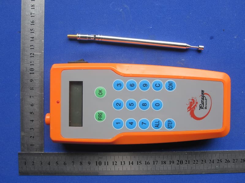
Click to zoom
Application Details
- Equipment Class
- DSC - Part 15 Security/Remote Control Transmitter
- Date of Grant
- Feb 16, 2012
- Application Purpose
- Original Equipment
- Date of Application
- Feb 16, 2012
- Equipment Note
- Fireworks Firing System
- Frequency Range
- 315.02000000 - 315.02000000
- Country
- China
Documents & Files
Document Text
Text extracted from the exhibit documents filed with the FCC. Open a document above to read the original.
Users Manual
Instruction of FS 2012 type of Igniting Controller Model: FS2012 Type System features: A. circuit ignition owns short circuit protection function, does not damage the chip. B. Each host can control 20 groups of fireworks ignition (150-200 meters for wireless remote control, 200-300 meters for wired remote control) C. Way of Ignition: 1: ALL TIME IS SAME. 2: Each group can be set for different time. D. Ignition time interval setting: 0.1-99.9 seconds E. Both stand-alone and multiple machines in series are available. F. Character type LCD display. G. Use the rechargeable batteries, battery power can be checked H. Even if the batteries are used up or removal, program design is still kept the same, must be re-set for elimination. System parameters: Ignition storage battery parameters 12V. 3.2AH (6V X 2PCS) Ignition instant ignition voltage ≥ 12V Ignition instant ignition current ≥ 2 AH Remote Control Battery: 9V battery (9V X 2PCS) Instructions: A. Power Supply Selection INT. means built-in power supply EXT. means external power supply External power supply 12-18V 1.3A-3.2A B. Power lock is set at ON position, if the button switch is in the FIRE state, shown as (-SWITCH-) FATAL ERROR, Please turn off the power. Switch to TEST state after a reboot. C. Under TEST state, 1 Press the MODE key to show ALL TIME IS SAME, press +10, +1, +0.1 to process time setting, set your request of ignition time interval, press OK button to confirm (disappearance of * symbol means confirmation). 2 Press the MODE button again to display 01 TO 02, then you can individually set the ignition time interval for each group, press +10, +1, +0.1 for time setting, LAST and NEXT button for selecting the firing position, set your required ignition time interval, press OK button for confirmation (disappearance of * symbol means confirmation), each group for time setting need to press OK for confirmation (disappearance of * symbol means confirmation) D: After completion of setting, check the setoff area, switch to FIRE state and wait for ignition signal after withdrawal of all staff. E. If choose the wireless remote control ignition, set the switch to the WIRELESS position; If you choose wired remote ignition, set the switch to the LINK position (requires line trigger 5V above ). F. Ignition head connection. 1: First, switch to the TEST position to prevent ignition errors in starting up. 2: Install corresponding test light for ignition head (green for light). 3: Switch to FIRE position and wait for the ignition signal. 3: Each ignition connector can be connected to each ignition, shown as following picture: G: Code checking 1: Set WIRELESS / LINK on WIRELESS position, code checking operation can be processed when ignition switch is placed at TEST position, and ignition error in starting up can be prevented. 2: Press OK and FIRE button on remote control and STUDY button on ignition, STUDY indicator lights means completion of the code checking; (If press OK and FIRE button on remote control, not press STUDY on ignition, STUDY lights, means code is accordant, do not need for checking). Instruction of Remote Control: FCC Statement This equipment has been tested and found to comply with the limits for a Class B digital device, pursuant to part 15 of the FCC rules. These limits are designed to provide reasonable protection against harmful interference in a residential installation. This equipment generates, uses and can radiate radio frequency energy and, if not installed and used in accordance with the instructions, may cause harmful interference to radio communications. However, there is no guarantee that interference will not occur in a particular installation. If this equipment does cause harmful interference to radio or television reception, which can be determined by turning the equipment off and on, the user is encouraged to try to correct the interference by one or more of the following measures: -Reorient or relocate the receiving antenna. -Increase the separation between the equipment and receiver. -Connect the equipment into an outlet on a circuit different from that to which the receiver is connected. -Consult the dealer or an experienced radio/TV technician for help. To assure continued compliance, any changes or modifications not expressly approved by the party responsible for compliance could void the user’s authority to operate this equipment. (Example- use only shielded interface cables when connecting to computer or peripheral devices). This equipment complies with Part 15 of FCC RF Rules. Operation is subject to the following two conditions: 1) This device may not cause interference and 2) This device must accept any interference, including interference that may cause undesired operation of the device.
External Photos
Report No.: TB-FCC122946 Page: 3 of 8 TB-RF-075-1.0 Appendix III EUT External Photographs Photo 1 Appearance of EUT Photo 2 Appearance of EUT Report No.: TB-FCC122946 Page: 4 of 8 TB-RF-075-1.0 Photo 3 Appearance of EUT Photo 4 Appearance of EUT Antenna Report No.: TB-FCC122946 Page: 5 of 8 TB-RF-075-1.0 Photo 5 Appearance of EUT
ID Label/Location Info
Report No.: TB-FCC122946 Page: 1 of 8 TB-RF-074-1.0 Appendix IID Label FCC ID: AYHFS2012
ID Label/Location Info
Report No.: TB-FCC122946 Page: 2 of 8 TB-RF-075-1.0 Appendix II ID Label Location FCC ID LOCATION
Internal Photos
Report No.: TB-FCC122946 Page: 6 of 8 TB-RF-075-1.0 Appendix IV EUT Internal Photographs Photo 6 Inside of EUT Photo 7 Appearance of PCB Report No.: TB-FCC122946 Page: 7 of 8 TB-RF-075-1.0 Photo 8 Appearance of PCB Photo 9 Appearance of PCB
Test Report
Shenzhen Meihua Electonic Technology Co., Ltd. Report No.: TB-FCC122946 Page: 1 of 28 TB-RF-074-1.0 Room 505, East DingXin Bldg., LiuXian Road, XiLi Town, Nanshan, Shenzhen, China Tel: +86 75526292087 Fax: +86 75526751700 FCC Radio Test Report FCC ID: AYHFS2012 Report No. : TB-FCC122946 Applicant : LIUYANG JUMBO TRADING COMPANY LTD. Equipment Under Test (EUT) EUT Name : Fireworks Firing System Model No. : FS2012-20 Cue Firing System Serial No. : 8A002-24 Cue Firing System, 8A015-40 Cue Firing System, 8A012-192 Cue Firing System, JF2011 12 Cue Firing System Brand Name : N/A Receipt Date : 2012-01-30 Test Date : 2012-02-01 to 2012-02-13 Issue Date : 2012-02-14 Tested By: : Bontek Compliance Testing Laboratory Ltd. Standards : FCC Part 15, Subpart C(15.231)/ANSI C63.4:2003 Test/Witness Engineer : Approved& Authorized : Report No.: TB-FCC122946 Page: 2 of 28 TB-RF-074-1.0 Contents CONTENTS.............................................................................................................................................2 TEST REPORT DECLARATION........................................................................................................4 1. GENERAL INFORMATION ABOUT EUT.............................................................................5 1.1 General Description of EUT (Equipment Under Test)...................................................5 1.2 Block Diagram Showing The Configuration of System Tested.....................................5 1.3 Description of Support Units..............................................................................................6 1.4 Description of Test Mode....................................................................................................6 1.5 Test Facility...........................................................................................................................6 2. TEST SUMMARY.......................................................................................................................7 3. CONDUCTED EMISSION TEST.............................................................................................8 3.1 Test Standard and Limit......................................................................................................8 3.2 Test Setup.............................................................................................................................8 3.3 Test Procedure.....................................................................................................................8 3.4 Test Equipment Used..........................................................................................................9 3.5 Test Data...............................................................................................................................9 4. RADIATED EMISSION TEST................................................................................................10 4.1 Test Standard and Limit....................................................................................................10 4.2 Test Setup...........................................................................................................................11 4.3 Test Procedure...................................................................................................................12 4.4 EUT Operating Condition.................................................................................................13 4.5 Test Equipment..................................................................................................................13 4.6 Test Condition....................................................................................................................13 4.7 Test Data.............................................................................................................................14 5. BANDWIDTH............................................................................................................................17 5.1 Test Standard and Limit....................................................................................................17 5.2 Test Setup...........................................................................................................................17 5.3 Test Procedure...................................................................................................................17 5.4 EUT Operating Condition.................................................................................................17 5.5 Test Equipment..................................................................................................................18 5.6 Test Condition....................................................................................................................18 5.7 Test Data.............................................................................................................................19 6. RELEASE TIME MEASUREMENT.......................................................................................20 6.1 Test Standard and Limit....................................................................................................20 6.2 Test Setup...........................................................................................................................20 6.3 Test Procedure...................................................................................................................20 6.4 EUT Operating Condition.................................................................................................20 6.5 Test Equipment..................................................................................................................21 6.6 Test Condition....................................................................................................................22 6.7 Test Data.....................................................................................…
Text truncated - open the document above for the full version.
Test Setup Photos
Report No.: TB-FCC122946 Page: 8 of 8 TB-RF-075-1.0 Appendix V EUT Test Photographs Photo of Setup for Radiated Emission (Above 1 GHz) Photo of Setup for Radiated Emission (Bellow 1 GHz)
Contact Information
Applicant
Willian Lau(Manager)
Test Firm
Bontek Compliance Testing Laboratory LtdTony Wu
Technical Specifications
| # | Rule Parts | Frequency Range | Power Output |
|---|---|---|---|
| 1 | 15.231 | 315.02 MHz - 315.02 MHz | - |