AZP-FDP032.4GHz Embedded Type Wireless Modem
Futaba Corporation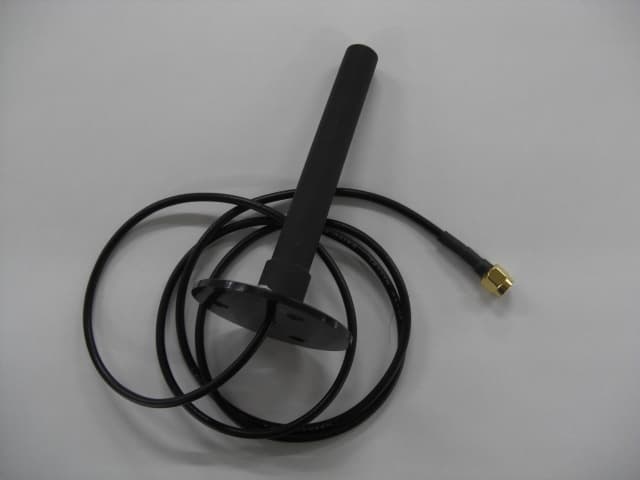
Click to zoom
Application Details
- Equipment Class
- DTS - Digital Transmission System
- Date of Grant
- Aug 04, 2010
- Application Purpose
- Original Equipment
- Date of Application
- Aug 03, 2010
- Equipment Note
- 2.4GHz Embedded Type Wireless Modem
- Frequency Range
- 2402.00000000 - 2477.00000000
- Company
- Futaba Corporation
- Country
- Japan
Documents & Files
Document Text
Text extracted from the exhibit documents filed with the FCC. Open a document above to read the original.
Users Manual
I WIRELESS DATA COMMUNICATION MODEM FDP03TJ010/020 2.4GHz Embedded Type Wireless Modem Instruction Manual Futaba Corporation Industrial Radio Control Ver.1.0 2 I Notice This device complies with part 15 of the FCC rules. Operation is subject to the following two conditions: (1) This device may not cause harmful interference, and (2) this device must accept any interference received, including interference that may cause undesired operation. This equipment has been tested and found to comply with the limits for a Class A digital device, pursuant to part 15 of the FCC Rules. These limits are designed to provide reasonable protection against harmful interference when the equipment is operated in a commercial environment. This equipment generates, uses, and can radiate radio frequency energy and, if not installed and used in accordance with the instruction manual, may cause harmful interference to radio communications. Operation of this equipment in a residential area is likely to cause harmful interference in which case the user will be required to correct the interference at her/his own expense. Any unauthorized changes or modifications to this device not expressly approved by Futaba Corporation could void the user’s authority to operate the device and possibly result in damage to the equipment and/or cause serious or fatal injuries to the operator or nearby personnel. This device is intended to be installed and used in accordance with the instructions contained in this manual. Failure to comply with these instructions could void the user’s authority to operate the device and possibly result in damage to the equipment and/or cause serious or fatal injuries to the operator or nearby personnel. II Important Safety Information The list of dangers, warnings and cautions in this section contain important information that will help ensure safe operation of the system. Please read carefully and understand all of these items. All installers, operators and maintenance personnel should read and understand this information before installation, use, or maintenance of the FDP03TJ010/020. The FDP03TJ010/020 system by itself is not inherently dangerous. HOWEVER, WHEN THE FDP03TJ010/020 IS CONNECTED TO OTHER EQUIPMENT FOR THE PURPOSE OF CONTROL, SAFETY AND ALL POSSIBLE ASSOCIATED DANGERS MUST ALWAYS BE GIVEN THE UTMOST CONSIDERATION DURING SYSTEM INTEGRATION, DESIGN, INSTALLATION, AND USE. The FDP03TJ010/020 may be used in virtually unlimited applications. Many of these associated systems can, by themselves, pose a mechanical, electrical or other hazard to operators and other persons or equipment. To address all possible applications and associated safety hazards in this manual would be impossible. The warnings below and throughout this manual give information that will allow safe installation and use the modem system applications. If you have questions regarding the safety of your specific application, please contact the appropriate people for help. Your Futaba sales representative, representatives of the equipment being controlled, and the technical support staff at local branch of Futaba Corporation are among those who can provide assistance with your safety concerns. The following warnings are included in the lists that follow but warrant repetition here: In installations where the FDP03TJ010/020 is used to control motion or operation of potentially dangerous equipment, it is imperative for safety that all operators and installers be thoroughly trained in the normal function of that equipment before attempting to control it remotely with the FDP03TJ010/020. Ver.1.0 3 To help ensure safe operation of the equipment, the FDP03TJ010/020 must be connected so that it will operate in a fail-safe way. In other words, the equipment being controlled should stop or return to its safest state in the absence of a control signal or total loss of RF transmission from the FDP03TJ010/020. Our system uses one of the most reliable methods available to transmit data using radio signals. Many factors can affect a radio signal that may block it or interfere enough to disrupt regular transmission. Because of this, equipment motion or dangerous electrical current, for example, that continues during a loss-of-signal condition could be very dangerous. Ver.1.0 4 Four symbols are used in the margin of the following section and throughout the manual to indicate the level of hazard or information listed. The symbols are defined as follows: Indicates a hazard that will cause severe personal injury, death, or substantial property damage if the warning is ignored. Indicates a hazard that can cause severe personal injury, death, or substantial property damage if the warning is ignored. Indicates a hazard that will or can cause minor personal injury, or property damage if the warning is ignored. Indicates installation, operation, or maintenance information that is important but not hazard-related. Please read the following safety information carefully. Some of these notices are duplicated throughout the manual, in areas of associated content, for your benefit. II.I General Safety Hazards and Notes Improper installation and/or operation of the FDP03TJ010/020 can cause serious or fatal injuries to the operator or nearby persons and cause damage to the FDP03TJ010/020, and any equipment it is used to control. Please read and understand this manual completely and the manual of all equipment being controlled before attempting to operate or install this system. Always keep this manual at a location readily accessible to anyone operating the system and related equipment. Ensure that all operators have read and understood this manual, especially all safety and operation procedures contained in it. Please refer to the section in this manual titled How to Obtain Help for the contact that can supply additional manuals or answers to questions not covered in this manual. If this product is passed on to a different user, be sure that this manual acco…
Text truncated - open the document above for the full version.
External Photos
Futaba Corporation 2.4GHz Embedded Type Wireless ModemFCC ID. : AZP-FDP03 EUT External Photos Figure 1 General Appearance (Front View) Figure 2 General Appearance (Back View) Futaba Corporation 2.4GHz Embedded Type Wireless ModemFCC ID. : AZP-FDP03 Figure 3 Fractus Slim Reach Xtend (Chip ANT) Figure 4 Pedestal Antenna ANT Futaba Corporation 2.4GHz Embedded Type Wireless ModemFCC ID. : AZP-FDP03 Figure 5 SMA(reverse) to U.FL. Figure 6 SMA(reverse) to U.FL.
External Photos
Pedestal antenna SMA(reverse) to U. FL cable:
ID Label/Location Info
Futaba Corporation 2.4GHz Embedded Type Wireless ModemFCC ID. : AZP-FDP03 FCC ID Label Location z Label Placement Location and Label Format FCC Label Placement Location FCC Label Format
Internal Photos
Futaba Corporation 2.4GHz Embedded Type Wireless ModemFCC ID. : AZP-FDP03 EUT Internal Photos Figure 7 PCB View Figure 8 PCB View
RF Exposure Info
Declaration of Compliance FCC ID : AZP-FDP03 Product Name : 2.4GHz Embedded Type Wireless Modem with chip antenna Model Number : FDP03 For chip antenna: Futaba Corporation declares that the product described above has been evaluated and found to comply with the RF exposure limits for humans, as specified based on ANSI/FCC recommendation. Based on safety distance 20cm, the antenna gain is 0dBi , and the power output is 3.4mW, the power density is 0.00067mW/cm^2. RF Exposure Calculations: S = (P * G) / (4* π * r^2) or r = (P * G) / (4 * π * S) Where S = Power Density in mW/cm^2 P = 5.32dBm = 3.4mW G = 0dBi = 1.0 Numerical r = 20cm S = 3.4*1 / 4*π* 20^2 =3.4/5026.56= 0.00067mW/cm^2 Limit MPE < 1mW/c m^2 For Pedestal: Futaba Corporation declares that the product described above has been evaluated and found to comply with the RF exposure limits for humans, as specified based on ANSI/FCC recommendation. Based on safety distance 20cm, the antenna gain is 2.14dBi , and the power output is 3.4mW, the power density is 0.0011mW/cm^2. RF Exposure Calculations: S = (P * G) / (4* π * r^2) or r = (P * G) / (4 * π * S) Where S = Power Density in mW/cm^2 P = 5.32dBm = 3.4mW G = 2.14dBi = 1.64 Nu merical r = 20cm S = 3.4*1.64 / 4*π* 20^2 =5.576/5026.56= 0.0011mW/cm^2 Limit MPE < 1mW/cm^2 Result: Passed Signature: _______________________________________ Soichi Shinya Deputy General-Manager Electronic Systems Division Futaba Corporation
Test Report
FCC ID. AZP-FDP03 Page 1 of 62 AUDIX Technology Corporation Report No. EM-F990786 APPLICATION FOR CERTIFICATION On Behalf of Futaba Corporation 2.4GHz Embedded Type Wireless Modem Model No.:FDP03 FCC ID:AZP-FDP03 Brand: Futaba Prepared for : Futaba Corporation 1080 Yabutsuka Chosei-son Chosei-gun Chiba, 299-4395 Japan. Prepared by : AUDIX Technology Corporation EMC Department No. 53-11, Tin-Fu Tsun, Lin-Kou Hsiang, Taipei Hsien, Taiwan Tel : (02) 2609-9301, 2609-2133 Fax: (02) 2609-9303 File Number : C1M1005110 Report Number : EM-F990786 Date of Test : Jun. 02 ~ Jul. 26, 2010 Date of Report : Jul. 30, 2010 FCC ID. AZP-FDP03 Page 2 of 62 AUDIX Technology Corporation Report No. EM-F990786 TABLE OF CONTENTS Description Page TEST REPORT CERTIFICATION .......................................................................................................4 1. GENERAL INFORMATION .......................................................................................................5 1.1. Description of Device (EUT).................................................................................................................. 5 1.2. Tested Supporting System Details .......................................................................................................... 6 1.3. Description of Test Facility .................................................................................................................... 6 1.4. Measurement Uncertainty....................................................................................................................... 7 2. POWERLINE CONDUCTED EMISSION MEASUREMET...................................................8 2.1. Test Equipment ....................................................................................................................................... 8 2.2. Block Diagram of Test Setup.................................................................................................................. 8 2.3. Powerline Conducted Emission Limit .................................................................................................... 8 2.4. Operating Condition of EUT .................................................................................................................. 9 2.5. Test Procedure ........................................................................................................................................ 9 2.6. Powerline Conducted Emission Measurement Results........................................................................... 9 3. RADIATED EMISSION MEASUREMENT ............................................................................14 3.1. Test Equipment ..................................................................................................................................... 14 3.2. Test Setup ............................................................................................................................................. 14 3.3. Radiated Emission Limits (§15.209) .................................................................................................... 16 3.4. Operating Condition of EUT ................................................................................................................ 16 3.5. Test Procedure ...................................................................................................................................... 16 3.6. Radiated Emission Measurement Results............................................................................................. 17 4. 6dB BANDWIDTH MEASUREMENT .....................................................................................42 4.1. Test Equipment ..................................................................................................................................... 42 4.2. Block Diagram of Test Setup................................................................................................................ 42 4.3. Specification Limits (§15.247(a)(2)) .................................................................................................... 42 4.4. Operating Condition of EUT ................................................................................................................ 42 4.5. Test Procedure ...................................................................................................................................... 42 4.6. Test Results........................................................................................................................................... 43 5. MAXIMUM PEAK OUTPUT POWER MEASUREMENT ...................................................45 5.1. Test Equipment ..................................................................................................................................... 45 5.2. Block Diagram of Test Setup................................................................................................................ 45 5.3. Specification Limits (§15.247(b)-(3))................................................................................................... 45 5.4. Operating Condition of EUT ................................................................................................................ 45 5.5. Test Procedure ...................................................................................................................................... 45 5.6. Test Results........................................................................................................................................... 46 6. EMISSION LIMITATIONS MEASUREMENT ......................................................................47 6.1. Test Equipment ..................................................................................................................................... 47 6.2. Block Diagram of Test Setup.................................................................…
Text truncated - open the document above for the full version.
Test Setup Photos
FCC ID. AZP-FDP03 Page 56 of 62 AUDIX Technology Corporation Report No. EM-F990786 10. PHOTOGRAPHS 10.1. Photos of Conducted Emission Measurement Test Mode: EUT with Fractus Slim Reach Xtend (Chip ANT) FRONT VIEW OF CONDUCTED MEASUREMENT BACK VIEW OF CONDUCTED MEASUREMENT FCC ID. AZP-FDP03 Page 57 of 62 AUDIX Technology Corporation Report No. EM-F990786 Test Mode: EUT with Pedestal Antenna FRONT VIEW OF CONDUCTED MEASUREMENT BACK VIEW OF CONDUCTED MEASUREMENT FCC ID. AZP-FDP03 Page 58 of 62 AUDIX Technology Corporation Report No. EM-F990786 10.2. Photos of Radiated Emission Measurement at Semi-Anechoic Chamber Test Mode: EUT with Fractus Slim Reach Xtend (Chip ANT) 10.2.1.Frequency Range 30MHz~1GHz z 10.2.2.Frequency Range Above 1GHz FCC ID. AZP-FDP03 Page 59 of 62 AUDIX Technology Corporation Report No. EM-F990786 Test Mode: EUT with Pedestal Antenna 10.2.3.Frequency Range 30MHz~1GHz 10.2.4.Frequency Range Above 1GHz FCC ID. AZP-FDP03 Page 60 of 62 AUDIX Technology Corporation Report No. EM-F990786 10.3. Photo of 6dB Bandwidth Measurement 10.4. Photo of Maximum Peak Output Measurement FCC ID. AZP-FDP03 Page 61 of 62 AUDIX Technology Corporation Report No. EM-F990786 10.5. Photo of Emission Limitations Measurement 10.6. Photo of Band Edges Measurement FCC ID. AZP-FDP03 Page 62 of 62 AUDIX Technology Corporation Report No. EM-F990786 10.7. Photo of Power Spectral Density Measurement
Contact Information
Applicant
Toshikazu Hama(Manager)
Technical Contact
AUDIX Technology CorporationBen Cheng
[email protected]886 2609-9301
No. 53-11, Tin-Fu Tsun, Lin-Kou Hsiang, · Taipei County · Taiwan
Test Firm
Audix Technology CorporationLeon Liu
Technical Specifications
| # | Rule Parts | Frequency Range | Power Output |
|---|---|---|---|
| 1 | 15C | 2.40 GHz - 2.48 GHz | 3.00 mW |
Other Applications from Futaba Corporation

AZP-FEX11T
Jan 22, 20262.4GHz band Module
Equipment Class
DSS - Part 15 Spread Spectrum Transmitter
AZPCGY770R-24G
Aug 19, 2024Radio Control
Equipment Class
DTS - Digital Transmission SystemAZPTM18
Jan 21, 2024Radio Control
Equipment Class
DSS - Part 15 Spread Spectrum TransmitterAZPR9001SB
Jan 17, 2024Radio Control
Equipment Class
DSS - Part 15 Spread Spectrum Transmitter
AZPR7201SB-24G
Jan 14, 2024Receiver
Equipment Class
DTS - Digital Transmission System