AZP-L35-N4581Radio Control Transmitter
Futaba Corporation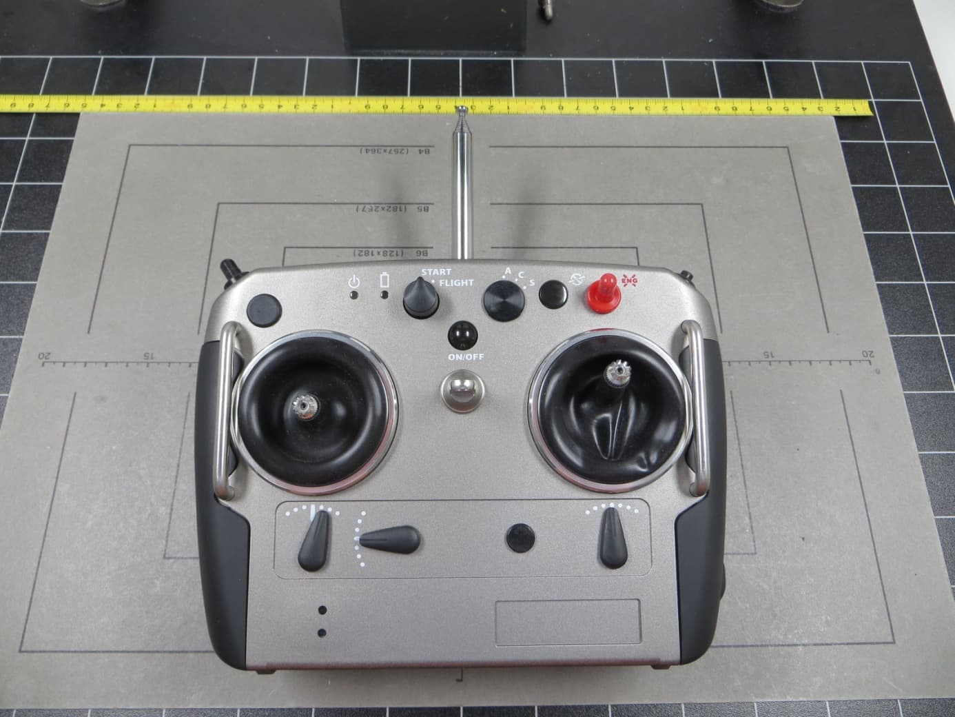
Click to zoom
Application Details
- Equipment Class
- TNB - Licensed Non-Broadcast Station Transmitter
- Date of Grant
- Aug 05, 2014
- Application Purpose
- Original Equipment
- Date of Application
- Aug 05, 2014
- Equipment Note
- Radio Control Transmitter
- Frequency Range
- 72.69000000 - 72.95000000
- Company
- Futaba Corporation
- Country
- Japan
Documents & Files
Document Text
Text extracted from the exhibit documents filed with the FCC. Open a document above to read the original.
Users Manual
L35-28199-00 Please read this manual before using the product. OPERATION MANUAL Unmanned Helicopter for Industrial Applications Foreword Thank you for purchasing the FAZER, an unmanned helicopter for industrial applications. This operation manual describes the proper method for operating the FAZER and precau- tions. Be sure to read this manual and thoroughly understand its contents before operating the FAZE R. In this manual, the warning messages that are necessary to ensure the safe and proper operation of the FAZER are classified as shown below. Make sure to observe these instruc- tions because they all contain important information. ●After you have read this operation manual, keep it within easy access near the helicopter. ●Contact your dealer if you are lending this helicopter or transferring its ownership. ●Keep this operation manual together with the helicopter if you are lending this helicopter or transferring its ownership. ●If you have lost this operation manual, contact your dealer to request another copy. ●Contact your dealer if you have any questions or comments regarding the contents of this operation manual. ●Due to specification changes, some of the textual or graphical contents of this manual may differ from the actual helicopter. ●For information regarding the sprayer, refer to the operation manual for the sprayer. Improper operation will cause imminent dan- ger, which could lead to serious injury or death. Improper operation could lead to injury, seri- ous injury or death. Improper operation could cause property damage. Describes the proper handling method or gives the main points for inspection and maintenance. Indicates a prohibited action. An adjacent illustration describes the prohibited action. DDANGER WWARNING NNOTICE TIP Table of Contents Safety Precautions1 Product Specifications2 Part Names and Functions3 Pre-Flight Preparation4 Flying Procedure5 Post-Flight Cleaning and Servicing6 Simple Maintenance7 Proper Management8 Product Management9 Troubleshooting10 Index11 Safety Precautions Product Safety Label Locations ................................................... 1-1 Make Sure to Follow the Instructions........................................... 1-2 Basic requirements .................................................................................................. 1-2 Operator requirements ............................................................................................. 1-3 Helicopter requirements ........................................................................................... 1-5 Flight requirements .................................................................................................. 1-7 Chemical requirements .......................................................................................... 1-11 1 1-1 Safety Precautions Read and thoroughly understand the product safety labels affixed to the helicopter before operation. Product Safety Label Locations Placed on the left and right. Safety Precautions 1-2 Basic requirements Make Sure to Follow the Instructions To ensure safe operation, make sure to thor- oughly read the operation manual before operation. WWARNING This unmanned helicopter for industrial applications has been manufactured for the purpose of the aerial application of agricul- tural chemicals, fertilizers, and seeds. Do not use it for other applications, which is in viola- tion of laws, and could lead to accidents. WWARNING Do not modify the helicopter or the auxiliary devices. Do not use parts other than genuine parts. Any modification of the helicopter or use of non-genuine parts may cause unex- pected accidents. WWARNING Safety Precautions 1-3 Operator requirements Observe the following clothing requirements: •Wear a helmet. •Wear goggles and a particle mask. •Wear long-sleeved clothing with secure buttons and fasteners. •Wear slip-proof shoes that are easy to walk with. • Do not wear objects that could obstruct vision when there is wind, or adversely affect operation (especially towels and gloves). Flying this helicopter requires a high level of skill. Therefore, it should be flown only by an oper- ator who holds an operator license for unmanned helicopters, issued by Yamaha Motor Co., Ltd. In addition, if the country where the unmanned helicopter will be used requires an operator license, obtain the license before flying the helicopter. WWARNING License Operator License for Unmanned Helicopters for Industrial Applications Name: Make sure to wear a helmet during flight. To perform an aerial application, make sure to wear clothing that is appropriate for the oper- ation. Performing a flight and an aerial appli- cation in clothing that is not appropriate for the task could cause loss of visibility, maneu- vering error, or cause your foot to slip, result- ing in unexpected accidents. Furthermore, it could harm your health through exposure to agricultural chemicals. WWARNING A minimum of three people is required for an aerial application: a signaler who has been briefed on the aerial application procedure, an assistant who readies, mixes, and sup- plies agricultural chemicals, and an operator. Beware that an understaffed operation could lead to an accident. WWARNING Safety Precautions 1-4 The operation of an unmanned helicopter involves considerable mental fatigue. The operator should not fly the helicopter contin- uously for more than one hour, but should take a rest every hour. Prolonged continuous flight operation could cause the operator to lose concentration and could lead to an acci- dent. Do not fly the helicopter after drinking alco- hol or taking a cold medicine, or if you are in poor physical condition. Flying the helicopter in poor physical condition could cause loss of concentration, and could lead to an acci- dent. WWARNING WWARNING Safety Precautions 1-5 Helicopter requirements Make sure to perform the following inspections. Have the 30-hour free inspection and periodic inspections performed…
Text truncated - open the document above for the full version.
Users Manual
Pre-Flight Preparation Day-Ahead Preparation ............................................................... 4-1 Charging and replacing the flight transmitter battery ............................................... 4-1 Charging and replacing the sprayer transmitter battery (sold separately) ............... 4-3 Fuel and refueling .................................................................................................... 4-4 Precautions for Initial Flight Following Periodic Inspection.......... 4-5 Fuel .......................................................................................................................... 4-5 Helicopter battery..................................................................................................... 4-5 Initial flight procedure............................................................................................... 4-5 Handling the Helicopter ............................................................... 4-6 Transporting the helicopter ...................................................................................... 4-6 Checking radio signal interference........................................................................... 4-9 Radio signal distance test ...................................................................................... 4-10 Main rotor installation and removal and tail rotor inspection .................................. 4-11 Side cover installation and removal ....................................................................... 4-13 4 4-1 Pre-Flight Preparation Charging and replacing the flight transmitter battery Charging the battery Be sure to use the dedicated charger for charging the battery. 1Place the battery on the charger. 2Insert the power plug into the outlet. The red lamp will illuminate while charging. 3After charging is complete, remove the battery. After the battery is fully charged, the red lamp will turn off. Refer to the following for the battery’s charging time and standard operation time. 4A warning lamp will indicate a warning if the bat- tery must be replaced during flight. (See page 3- 12.) Day-Ahead Preparation Make sure to use a fully charged battery for a flight. An insufficiently charged battery can lead to an operation failure. Charging temperature range: 0 to 40 °C Charging time: 4 hours Standard operation time: 4 hours minimum WWARNING Pre-Flight Preparation 4-2 Battery replacement Replace the battery as follows. 1Loosen the 2 battery cover knobs behind the transmitter by turning them 90 degrees to the left. 2Open the battery cover. 3Unlock the battery lock, slide and remove the battery to the left. 4Insert a charged battery and slide it to the right. 5Close the battery cover, and turn and tighten the battery cover knobs 90 degrees to the right. Battery storage Battery cover knobs Battery cover Battery lock Do not use the battery or leave it in an area exposed to direct sunlight or in other high- temperature areas such as inside a sun- scorched car. Store it between -20 °C and 50 °C. NNOTICE Pre-Flight Preparation 4-3 Charging and replacing the sprayer transmitter battery (sold sepa- rately) Charging the battery Be sure to use a dedicated charger to charge the battery. Charge it as follows. 1Make sure the power switch on the transmitter is OFF. 2Remove the battery cover from the bottom. 3Insert the charger’s plug into the charging jack at the bottom of the transmitter. 4Insert the power plug into the outlet. 5The pilot lamp of the charger will illuminate, thus charging the battery. Refer to the following for the battery’s charging time and standard operation time. 6After charging is complete, reattach the battery cover. Make sure to use a fully charged battery. An insufficiently charged battery can lead to a sprayer operation failure. Charging temperature range: 0 to 40°C Charging time: 10 hours Standard operation time: 2.1 to 3.3 hours If a battery is new or has been in long stor- age, its operation time after the initial charge can be shorter than normal. In this case, the battery’s normal performance with respect to the operation time will recover after several times of repeated charging and discharging. Please remember about this aspect during an initial use. NNOTICE NNOTICE Charging jack Dedicated charger Battery cover Pre-Flight Preparation 4-4 Fuel and refueling This product uses regular gasoline. Do not mix engine oil with gasoline. 1Have regular gasoline ready. Use fresh gasoline purchased recently (within 1 week) from a gasoline station. 2Remove the fuel tank cap and start refueling. Make sure the filter net is attached to the filler inlet. ●Stop the engine before refueling and do not bring a source of fire in the vicinity. ●Do not pour fuel over the refueling limit (the red line marked in the filter net). Excess fuel can ooze out during flight, which is dangerous. ●After refueling, securely tighten the fuel tank cap. The fuel can spray out of the tank during storage or transport in a vehicle with high temperature. WWARNING NNOTICE Fuel tank cap Fuel tank Refueling limit (red line) Filter net Pre-Flight Preparation 4-5 Fuel After the helicopter undergoes a test flight following the completion of a periodic inspection at the dealer, the fuel is drained from the fuel tank. This prevents the fuel from getting stale while the helicopter is being stored by the customer. Before the customer takes the helicopter on an initial flight, fill the tank with fresh gasoline purchased recently (within 1 week) from a gasoline stand. Helicopter battery Because the tank was drained of its fuel, it will take a while for the fuel to reach the engine. If the engine does not start within 5 seconds after the starter switch is pressed, allow the starter to rest for about 10 seconds. This is done to allow the battery voltage to recover and to cool the starter motor. Then, press the starter switch again. If the starter motor spins weakly, replace the helicopter battery or recharge it…
Text truncated - open the document above for the full version.
Users Manual
Simple Maintenance 7-8 5Tail transmission ●Check that there is no oil leakage. 6Check engine oil level ●Check the oil level on the level gauge when the engine is cold or 3 or more minutes have elapsed after stopping the engine. If the oil is more than the maximum level or less than the minimum level, contact your dealer. Tail transmission Maximum level Minimum level Simple Maintenance 7-9 4. Main head area inspection (before and after) Before performing this inspection, turn OFF both the main switch for the helicopter and the power switch for the transmitter. 1Stabilizer ●Check the stabilizer for any deformation. ●Check that the stabilizer blade and stabilizer bar are installed securely, without any looseness. ●Check that the stabilizer bar does not wobble in axial direction. ●Check the portion that mounts to the main mast for any looseness. Main mast Stabilizer bladeStabilizer bar Simple Maintenance 7-10 2Main rotor, yoke, blade holder ●Check the main rotor blades for cracks or chip- ping. * Contact your dealer if you see any cracks in the painted surface. ●Check that the cushion tape is not peeling or deteriorated. * Excessive peeling can adversely affect flight. ●Blade edge wear inspection * Contact your dealer if you see excessive wear. ●Check the yoke and blade holder for any defor- mation or cracks. ●Check the pitch arm for any deformation. ●Check that the pitch arm and blade holder are installed without any looseness or wobble. 3Swash plate and linkage inspection ●Check that the swash plate and linkage (rod) are installed without any wobble. ●Check the installed areas for any cracks or defor- mation. 4Main mast ●Check the main mast retaining nuts for any looseness. Main rotor Cushion tape Pitch arm Blade holder Yo k e Swash plateLinkage Main mast retaining nut Simple Maintenance 7-11 5. Tail body area inspection (before and after) Before performing this inspection, turn OFF both the main switch for the helicopter and the power switch for the transmitter. 1Tail body ●Check the tail body for any damage. ●Check the tail body retaining bolts for any loose- ness. 2Antenna ●For inspection details, refer to the section on “Helicopter antenna inspection”. 3Tail cover ●Check the tail cover for any deformation or cracks. ●Check that the tail cover is attached securely. Tail body Retaining bolt Tail cover Simple Maintenance 7-12 4Stone guard ●Check that it is attached securely. ●Check that there are no lamination cracks. 5Tail rotor ●Check the tail rotor blades for any damage. ●Check that the cushion tape is not peeling or deteriorated. ●Check the blade edges for any damage. ●Check that it moves properly in the direction of rotation. ●Check the bearing seal cap for any damage or deterioration. ●Check the drag bolts and nuts for any damage. ●Move it manually to give it thrust, and check that it moves smoothly. Stone guard Tail rotor blade Cushion tape Bearing seal cap Simple Maintenance 7-13 6. Drive shaft inspection (before and after) Before performing this inspection, turn OFF both the main switch for the helicopter and the power switch for the transmitter. 1Drive shaft and flange coupling ●Check the drive shaft for any damage. ●Check the portion that mounts to the flange cou- pling for any problems. Drive shaft Flange coupling Simple Maintenance 7-14 7. Servo inspection (before and after) Inspect the servos and linkages for proper opera- tion. Before performing this test, turn ON both the main switch for the helicopter and the power switch for the transmitter. 1Slide servo inspection Slowly move the throttle, elevator, and aileron sticks up and down and side-to-side. Inspect that the servos and linkages move smoothly in uni- son with the sticks. Also, inspect that the link- ages do not wobble. 2Throttle inspection ●Throttle fully open, and fully closed •With the throttle stick in its maximum posi- tion, inspect that the throttle body pulley on the throttle body moves to its fully open position. •With the throttle stick in its slowest position, inspect that the throttle body pulley on the throttle body moves to its fully closed posi- tion. ●Throttle cable movement and play • Move the throttle stick slowly up and down, and inspect that the cable moves smoothly without getting caught. •With the throttle body pulley fully closed, inspect that the cable has slight play. * Check the throttle valve movement by way of the pulley movement. Slide servo Throttle body pulley Throttle cable Simple Maintenance 7-15 3Rudder servo inspection Slowly move the throttle and rudder sticks up and down and side-to-side. Inspect that the ser- vos and linkages move smoothly in unison with the sticks. Also, inspect that the linkages do not wobble. If the servos operate improperly or the linkages wobble, cancel the flight and ask your dealer for a repair. 8. Self monitor inspection (before and after) Inspect the self monitor for any abnormal condition. Before performing this test, turn ON both the main switch for the helicopter and the power switch for the trans- mitter. Refer to page 3-10 for details. If the lamp indications are improper, have them repaired at your dealer before your next flight. 9. Radio signal distance test (before) Refer to page 4-10 for details. ●If the servos do not operate properly or the linkages wobble, they can negatively affect the control of the helicopter. ●If the throttle does not operate properly, it can negatively affect engine control and disable flight control. WWARNING Take appropriate actions if the self monitor indicates an error. Ignoring it and continuing to fly in this manner will disable the flight control, which can lead to a serious accident. WWARNING Simple Maintenance 7-16 10. Electrical system inspection (before and after) Before performing this inspection, turn OFF both the main switch for the helicopter and the power switch for the transmitter. 1Slide servo ●Check that the wiring harness coupler is securely engaged. 2Cylinder ●Check that the spark plug cap is placed s…
Text truncated - open the document above for the full version.
Cover Letter(s)
Seite 1 von 1 TÜV SÜD Product Service GmbH Äußere Frühlingstraße 45 94315 Straubing Germany Tel: +49-9421-5522-0 Fax: +49-9421-5522-99 www.tuev-sued.de Federal Communications Commission Authorization and Evaluation Division Application for certification of FCC ID AZP-L35-N4581 Gentlemen: This is to confirm that: • The sprayer transmitter was not included in the test sample at the date of testing and • This Sprayer Transmitter was not included in this testing and certification project. Sincerely, p.p. Johann Roidt TÜV SÜD Product Service GmbH TÜV SÜD Product Service GmbH • Äußere Frühlingstraße 45 • 94315 Straubing • Deutschland Ihre Zeichen/Nachricht vom Unsere Zeichen/Name Tel.-Durchwahl/E-Mail Fax-Durchwahl Datum Seite Johann Roidt 09421 – 5522 – 0 09421 – 5522 – 99 01. August 2014 1 von 1 [email protected]
External Photos
FCC ID: AZP-L35-N4581 FCC ID: AZP-L35-N4581 FCC ID: AZP-L35-N4581 FCC ID: AZP-L35-N4581 FCC ID: AZP-L35-N4581 FCC ID: AZP-L35-N4581 FCC ID: AZP-L35-N4581 FCC ID: AZP-L35-N4581 FCC ID: AZP-L35-N4581 FCC ID: AZP-L35-N4581 FCC ID: AZP-L35-N4581
ID Label/Location Info
ᝅFCC Label Design ⊅FRTD11TBA0 ⊅FRTD12TBB0 ⊅FRTD14TBD0 ⊅FRTD15TBE0 FCC ID AZP-L35-N4581
Internal Photos
Page 1 of 8 FCC ID AZP-L35-N4581 – Internal Photos Page 2 of 8 FCC ID AZP-L35-N4581 – Internal Photos Page 3 of 8 FCC ID AZP-L35-N4581 – Internal Photos Page 4 of 8 FCC ID AZP-L35-N4581 – Internal Photos Page 5 of 8 FCC ID AZP-L35-N4581 – Internal Photos Page 6 of 8 FCC ID AZP-L35-N4581 – Internal Photos Page 7 of 8 FCC ID AZP-L35-N4581 – Internal Photos Page 8 of 8 FCC ID AZP-L35-N4581 – Internal Photos
Test Report
Note: The test data of this report is related only to the individual item which has been tested. This report shall not be reproduced except in full extent without the written approval of the testing laboratory. Trade Register Munich HRB 85742 VAT ID No. DE129484267 Information pursuant to Section 2(1) DL-InfoV (Germany) at www.tuev-sued.com/imprint Supervisory Board: Dirk Eilers Management: Robert Kees Dr. Jens Butenandt Phone: +49 9421 55 22-0 Fax: +49 9421 55 22-99 www.tuev-sued.de TÜV SÜD Product Service GmbH Äußere Frühlingstraße 45 94315 Straubing Germany Prüfbericht / Test Report Nr. / No. 69582-43757-1 (Edition 1) Auftraggeber Applicant Futaba Corporation Geräteart Type of equipment Transmitter for Radio control system 72 MHz Typenbezeichnung Type designation FRT-Tx Auftragsnummer / Order No. -- Prüfgrundlage Test standards FCC Code of Federal Regulations, CFR 47, Part 95, Subpart C&E FCC Code of Federal Regulations, CFR 47, Part 2, Subpart J 16 July 2014 Page 1 of 51 TÜV SÜD Product Service GmbH Äußere Frühlingstraße 45 94315 Straubing Germany Phone: +49 9421 5522-0 Fax: +49 9421 5522-99 Web: www.tuev-sued.de Test Report No. 69582-43757-1 (Edition 1) Page 2 of 51 Pages Table of Contents 1 Description of the Equipment Under Test (EUT) ......................................................... 3 2 Administrative Data ..................................................................................................... 4 3 Identification of the Test Laboratory ............................................................................ 5 4 Summary ..................................................................................................................... 6 5 Operation Mode and Configuration of EUT ................................................................. 7 6 Measurement Procedures ........................................................................................... 8 6.1 Maximum Transmitter Power ................................................................................ 8 6.2 Frequency tolerance ........................................................................................... 11 6.3 Emission Bandwidth ............................................................................................ 13 6.4 Unwanted Emission 30 MHz - 1 GHz .................................................................. 14 7 Photographs Taken During Testing ........................................................................... 17 8 Test Results .............................................................................................................. 21 8.1 Maximum transmitter power ................................................................................ 22 8.2 Carrier Frequency Stability .................................................................................. 28 8.3 Emission Bandwidth ............................................................................................ 35 8.4 Unwanted Radiation 30 MHz - 1 GHz ................................................................. 39 9 Referenced Regulations ............................................................................................ 49 10 Test Equipment List with Calibration Data ................................................................. 50 11 Revision History ........................................................................................................ 51 TÜV SÜD Product Service GmbH Äußere Frühlingstraße 45 94315 Straubing Germany Phone: +49 9421 5522-0 Fax: +49 9421 5522-99 Web: www.tuev-sued.de Test Report No. 69582-43757-1 (Edition 1) Page 3 of 51 Pages 1 Description of the Equipment Under Test (EUT) General data of EUT Type designation 1 : FRT-Tx Parts 2 : Lithium-ion Battery pack (2UR18650F)c Serial number(s): 121100039 Manufacturer: Futaba Corporation Type of equipment: Transmitter for Radio control system 72 MHz Version: As received FCC ID: AZP-L35-N4581 Additional parts/accessories: Technical data of EUT Application frequency range: 72.01 MHz - 72.99 MHz Frequency range: 72.69 MHz – 72.95 MHz Operating frequency: 72.950 MHz Type of modulation: FSK Pulse train: Not Applicable Pulse width: Not Applicable Number of RF-channels: 10 Channel spacing: 8 kHz Designation of emissions 3 : 10K0F1D Type of antenna: Telescope antenna Size/length of antenna: 110 cm Connection of antenna: detachable not detachable Type of power supply: Battery supply (Lithium-ion Battery) Specifications for power supply: nominal voltage: 7.40 V minimum voltage: 6.29 V maximum voltage: 8.51 V nominal frequency: DC Hz 1 Type designation of the system if EUT consists of more than one part. 2 Type designations of the parts of the system, if applicable. 3 Also known as "Class of Emission". TÜV SÜD Product Service GmbH Äußere Frühlingstraße 45 94315 Straubing Germany Phone: +49 9421 5522-0 Fax: +49 9421 5522-99 Web: www.tuev-sued.de Test Report No. 69582-43757-1 (Edition 1) Page 4 of 51 Pages 2 Administrative Data Application details Applicant (full address): Futaba Corporation 1080, Yabutsuka Chosei-mura, Chosei-gun, Chiba-ken 299-4395 Japan Contact person: Mr. Masaki Wakatsuki Contract identification: -- Receipt of EUT: 2014-06-10 Date(s) of test: 2014-06-10 - 2014-06-15 Note(s): -- Report details Report number: 69582-43757-1 Edition: 1 Issue date: July 16, 2014 TÜV SÜD Product Service GmbH Äußere Frühlingstraße 45 94315 Straubing Germany Phone: +49 9421 5522-0 Fax: +49 9421 5522-99 Web: www.tuev-sued.de Test Report No. 69582-43757-1 (Edition 1) Page 5 of 51 Pages 3 Identification of the Test Laboratory Details of the Test Laboratory Company name: TÜV Süd Product Service GmbH Address: Aeussere Fruehlingstrasse 45 D-94315 Straubing Germany Laboratory accreditation: DAkkS Registration No. D-PL-11321-11-01 FCC test site registration number 90926 Industry Canada test site registration: 3050A-2 Contact person: Mr. Johann Roidt Phone: (+49) (0)9421 5522-0 Fax: (+49) (0)9421 5522-99 TÜV SÜD …
Text truncated - open the document above for the full version.
Test Setup Photos
TÜV SÜD Product Service GmbH Äußere Frühlingstraße 45 94315 Straubing Germany Phone: +49 9421 5522-0 Fax: +49 9421 5522-99 Web: www.tuev-sued.de Test Report No. 69582-43757-1 (Edition 1) Page 18 of 51 Pages Test setup for radiated emission measurement (alternative test site) TÜV SÜD Product Service GmbH Äußere Frühlingstraße 45 94315 Straubing Germany Phone: +49 9421 5522-0 Fax: +49 9421 5522-99 Web: www.tuev-sued.de Test Report No. 69582-43757-1 (Edition 1) Page 19 of 51 Pages Test setup for radiated emission measurement (fully anechoic room) - continued - TÜV SÜD Product Service GmbH Äußere Frühlingstraße 45 94315 Straubing Germany Phone: +49 9421 5522-0 Fax: +49 9421 5522-99 Web: www.tuev-sued.de Test Report No. 69582-43757-1 (Edition 1) Page 20 of 51 Pages Test setup for carrier frequency stability measurement
Contact Information
Applicant
Toshikazu Hama(Manager)
Test Firm
TUV SUD Product Service GmbH PS-EMC-STRRainer Heller
Technical Specifications
| # | Rule Parts | Frequency Range | Power Output | Emission | Tolerance |
|---|---|---|---|---|---|
| 1 | 95C | 72.69 MHz - 72.95 MHz | 224.00 mW | 8K00F1D | 20.0000000000 ppm |
Other Applications from Futaba Corporation

AZP-FEX11T
Jan 22, 20262.4GHz band Module
Equipment Class
DSS - Part 15 Spread Spectrum Transmitter
AZPCGY770R-24G
Aug 19, 2024Radio Control
Equipment Class
DTS - Digital Transmission SystemAZPTM18
Jan 21, 2024Radio Control
Equipment Class
DSS - Part 15 Spread Spectrum TransmitterAZPR9001SB
Jan 17, 2024Radio Control
Equipment Class
DSS - Part 15 Spread Spectrum Transmitter
AZPR7201SB-24G
Jan 14, 2024Receiver
Equipment Class
DTS - Digital Transmission System