AZP-R7208SB-24GRECEIVER
Futaba Corporation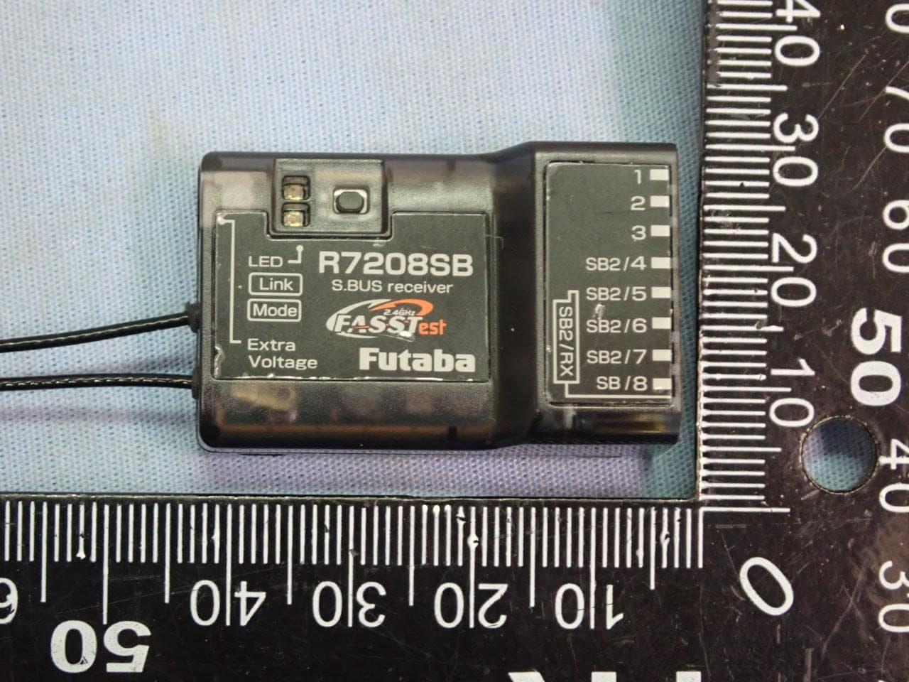
Click to zoom
Application Details
- Equipment Class
- DTS - Digital Transmission System
- Date of Grant
- Nov 23, 2022
- Application Purpose
- Original Equipment
- Date of Application
- Nov 22, 2022
- Equipment Note
- RECEIVER
- Frequency Range
- 2405.37600000 - 2472.96000000
- Company
- Futaba Corporation
- Country
- Japan
Documents & Files
Document Text
Text extracted from the exhibit documents filed with the FCC. Open a document above to read the original.
Users Manual
R7208SB Thank you for purchasing a Futaba R7208SB FASSTest-2.4GHz compatible receiver. The R7208SB receiver features bi-directional communication with a FASSTest Futaba transmitter using the S.BUS2 port. Using the S.BUS2 port an impressive array of telemetry sensors may be utilized. It also includes both standard PWM output ports (1-8ch) and S.BUS output ports. The R7208SB can also be switched to the Dual Rx Link System. This system can ensure safety by mounting two receivers on one aircraft. 1M23N38308 ● Applicable systems: Futaba FASSTest-2.4GHz system transmitter ◆ FASSTest-2.4GHz Bidirectional Communication System ◆ Dual Rx Link System Equipment ◆ S.BUS2 / S.BUS Port and 8 Channels for Conventional System Receiver Antenna installation for carbon fuselage You must leave 30mm at the tip of the antenna fully exposed. The exposed antenna should be secured so that it cannot move around or back inside of your aircraft. Be careful of connector insertion Don't connect an S.BUS servo / gyro to S.BUS2 connector. Link precaution Do not perform the linking procedure while the motor's main power is connected or the engine is operating as it may result in serious injury. When the linking is complete, please cycle the receiver power and ensure the receiver is properly linked to the transmitter. Please power up your system in this order: Transmitter first, followed by the receiver. If the R7208SB receiver was previously linked to another transmitter, make sure that transmitter is not operating while linking the receiver to the new transmitter. Connector precaution Don't connect a connector, as shown in a before figure. ■ It will short-circuit, if it connected in this way. A short circuit across the battery terminals may cause abnormal heating, fire and burns *Be sure that when using ESCs regulated output the capacity of the ESC must meet your usage condition. *Never use dry batteries for the power sup- ply of the R7208SB as they may cause difficulties. Usage precaution • Analog servos cannot be used with the R7208SB in the FASSTest 12CH mode. • Don't connect to Extra Voltage before turning on a receiver. WARNING Changes or modification not approved by the party responsible for compliance could void the user’s authority to operate the equipment. The R7208SB receiver should be protected from vibration by foam rubber, Velcro, or similar mounting methods. Protect from moisture. Keep away from conductive materials to avoid short circuits. Antenna installation precaution Do not cut or bundle the receiver antenna wire. Do not bend the coaxial cable. It causes damage. The antennas must be mounted in such a way to assure they are strain relieved. Keep the antenna as far away from the motor, ESC and other noise sources as you possibly can. Do not touch the antenna to metal, carbon, or other conductive material. Be sure that the two antennas are placed at 90 degrees to each other. ■The R7208SB has two antennas. In order to maximize signal reception and promote safe modeling Futaba has adopted a diversity antenna system. This allows the receiver to obtain RF signals on both antennas and fly problem-free. R7208SB Specifications FASSTest-2.4 GHz system(18 ch/12 ch mode) S.BUS2 and S.BUS port and 8 channels for conventional system receiver • Dual antenna diversity • Size: 0.98 x 1.53 x 0.56 in. (24.9 x 38.8 x 14.3 mm) • Weight: 0.39 oz. (11.0 g) • Power requirement: 3.7 V to 7.4 V(Voltage range: 3.5 V to 8.4 V) • Battery F/S Voltage: It sets up with a transmitter • Extra Voltage port: 0 ~ 70 V DC Servo for conventional system Mode LED Link LED Antenna Mode switch Extra Voltage Port (It is not used for a link.) It connects with the battery for power, etc. External voltage input cable of an option is used. The voltage of the battery can be displayed with a transmitter. S.BUS Servo S.BUS Gyro HUB HUB HUBHUB HUB R7208SB HUB Battery 3.7~7.4 V Switch Servo When all ports are used. A battery is connectable also with which port. Temperature Sensor Voltage Sensor Voltage Sensor RPM Sensor Altitude Sensor Airspeed Sensor S.BUS2 Tool S.BUS2 port (S.BUS2) S.BUS port (8/SB) Channel 8 output Channel 1 output + - (Typical installation) Receiver Do not insert either a switch or battery in this manner. DANGER Compliance Information Statement (for U.S.A.) This device, trade name Futaba Corporation, model number R7208SB, complies with part15 of the FCC Rules. Operation is subject to the following two conditions: (1) This device may not cause harmful interference, and (2) This device must accept any interference received, including interference that may cause undesired operation. CAUTION: To assure continued FCC compliance 1. Any changes or modifications not expressly approved by the grantee of this device could void the user's authority to operate the equipment. 2. This equipment complies with FCC radiation exposure limits set forth for an uncontrolled environment. This equipment should be installed and operated with minimum distance 20cm between the radiator & your body. The responsible party of this device compliance is: FUTABA Corporation of America 2681 Wall Triana Hwy Huntsville, AL 35824, U.S.A. Phone:1-256- 461-9399 FAX:1-256- 461-1059 E-mail: ser [email protected] Compliance Information Statement (for Canada) This device complies with Industry Canada license-exempt RSS standard(s). Operation is subject to the following two conditions: (1) this device may not cause interference, and (2) this device must accept any interference, including interference that may cause undesired operation of the device. This equipment com- plies with IC radiation exposure limits set forth for an uncontrolled environment. This equipment should be installed and operated with minimum distance 20cm between the radiator & your body. French: Cet appareil radio est conforme au CNR-210 d’Industrie Canada. L’utilisation de ce dispositifest autorisée seulement aux deux conditions suivantes : (1) il ne doit pas produire de brouillage, et (2) l’utilisateur …
Text truncated - open the document above for the full version.
Users Manual
R7308SB Thank you for purchasing a Futaba R7308SB FASSTest-2.4GHz compatible receiver. The R7308SB receiver features bi-directional communication with a FASSTest Futaba transmitter using the S.BUS2 port. Using the S.BUS2 port an impressive array of telemetry sensors may be utilized. It also includes both standard PWM output ports (1-8ch) and S.BUS output ports. The R7308SB can also be switched to the Dual Rx Link System. This system can ensure safety by mounting two FASSTest receivers on one aircraft. 1M23N38310 ● Applicable systems: Futaba FASSTest-2.4GHz system transmitter ◆ FASSTest-2.4GHz Bidirectional Communication System ◆ Dual Rx Link System Equipment ◆ S.BUS2 / S.BUS Port and 8 Channels for Conventional System Receiver Antenna installation for carbon fuselage You must leave 30mm at the tip of the antenna fully exposed. The exposed antenna should be secured so that it cannot move around or back inside of your aircraft. Be careful of connector insertion Don't connect an S.BUS servo / gyro to S.BUS2 connector. Link precaution Do not perform the linking procedure while the motor's main power is connected or the engine is operating as it may result in serious injury. When the linking is complete, please cycle the receiver power and ensure the receiver is properly linked to the transmitter. Please power up your system in this order: Transmitter first, followed by the receiver. If the R7308SB receiver was previously linked to another transmitter, make sure that transmitter is not operating while linking the receiver to the new transmitter. Connector precaution Don't connect a connector, as shown in a before figure. ■ It will short-circuit, if it connected in this way. A short circuit across the battery terminals may cause abnormal heating, fire and burns *Be sure that when using ESCs regulated output the capacity of the ESC must meet your usage condition. *Never use dry batteries for the power sup- ply of the R7308SB as they may cause difficulties. Usage precaution • Analog servos cannot be used with the R7308SB in the FASSTest 12CH mode. • Don't connect to Extra Voltage before turning on a receiver. WARNING Changes or modification not approved by the party responsible for compliance could void the user’s authority to operate the equipment. The R7308SB receiver should be protected from vibration by foam rubber, Velcro, or similar mounting methods. Protect from moisture. Keep away from conductive materials to avoid short circuits. Antenna installation precaution Do not cut or bundle the receiver antenna wire. Do not bend the coaxial cable. It causes damage. The antennas must be mounted in such a way to assure they are strain relieved. Keep the antenna as far away from the motor, ESC and other noise sources as you possibly can. Do not touch the antenna to metal, carbon, or other conductive material. Be sure that the two antennas are placed at 90 degrees to each other. ■The R7308SB has two antennas. In order to maximize signal reception and promote safe modeling Futaba has adopted a diversity antenna system. This allows the receiver to obtain RF signals on both antennas and fly problem-free. R7308SB Specifications FASSTest-2.4 GHz system(18 ch/12 ch mode) S.BUS2 and S.BUS port and 8 channels for conventional system receiver • Dual antenna diversity • Sleeve antenna • Size: 0.98 x 1.53 x 0.56 in. (24.9 x 38.8 x 14.3 mm) • Weight: 0.39 oz. (11.0 g) • Power requirement: 3.7 V to 7.4 V(Voltage range: 3.5 V to 8.4 V) • Battery F/S Voltage: It sets up with a transmitter • Extra Voltage port: 0 ~ 70 V DC Servo for conventional system Mode LED Link LED Antenna Mode switch Extra Voltage Port (It is not used for a link.) It connects with the battery for power, etc. External voltage input cable of an option is used. The voltage of the battery can be displayed with a transmitter. S.BUS Servo S.BUS Gyro HUB HUB HUBHUB HUB R7308SB HUB Battery 3.7~7.4 V Switch Servo When all ports are used. A battery is connectable also with which port. Temperature Sensor Voltage Sensor Current Sensor RPM Sensor Altitude Sensor Airspeed Sensor S.BUS2 Tool S.BUS2 port (S.BUS2) S.BUS port (8/SB) Channel 8 output Channel 1 output + - (Typical installation) Receiver Do not insert either a switch or battery in this manner. DANGER Compliance Information Statement (for U.S.A.) This device, trade name Futaba Corporation, model number R7308SB, complies with part15 of the FCC Rules. Operation is subject to the following two conditions: (1) This device may not cause harmful interference, and (2) This device must accept any interference received, including interference that may cause undesired operation. CAUTION: To assure continued FCC compliance 1. Any changes or modifications not expressly approved by the grantee of this device could void the user's authority to operate the equipment. 2. This equipment complies with FCC radiation exposure limits set forth for an uncontrolled environment. This equipment should be installed and operated with minimum distance 20cm between the radiator & your body. The responsible party of this device compliance is: FUTABA Corporation of America 2681 Wall Triana Hwy Huntsville, AL 35824, U.S.A. Phone:1-256- 461-9399 FAX:1-256- 461-1059 E-mail: ser [email protected] The The R7308SBR7308SB has a port switching has a port switching function. If function. If SB2/4SB2/4 to to SB2/7SB2/7 ports are also ports are also set to S.BUS2, sensors can be connected.set to S.BUS2, sensors can be connected. RED ⇒ ORANGE ⇒ GREEN ⇒ ORANGE slow blink Blinks ORANGE once Blinks ORANGE twice Blinks ORANGE Solid ORANGE FASSTest12CH(Telemetry OFF)mode : ON FASSTest12CH(Telemetry OFF)mode : OFF 4 Press switch Press SW once more to return to flashing orange once 3 5 Press and hold the SW 6 Release SW Release the switch here 7 Turn off the receiver power Blinking switches every 5 seconds as follows. 1 Turn on the receiver. [T ransmitter is always OFF] 2 Press and hold the SW for 5 seconds or more. FASSTest12CH(Telemetry OFF)mo…
Text truncated - open the document above for the full version.
External Photos
FUTABA Corporation RECEIVER Model : (1)R7208SB (2)R7308SB EUT External Photos Figure 1 General Appearance with Antenna Ant 1-Black (ANTB24-104A0) Model: R7208SB, Full View Figure 2 General Appearance with Antenna Ant 2-Gray (UFL-LP6-068N1T-A11-T-153D) Model: R7208SB, Full View Antenna Antenna FUTABA Corporation RECEIVER Model : (1)R7208SB (2)R7308SB Figure 3 General Appearance with Antenna Ant 1-Black (ANTB24-104A0) Model: R7208SB, Top View Figure 4 General Appearance with Antenna Ant 1-Black (ANTB24-104A0) Model: R7208SB, Bottom View FUTABA Corporation RECEIVER Model : (1)R7208SB (2)R7308SB Figure 5 General Appearance with Antenna Ant 1-Black (ANTB24-104A0) Model: R7208SB, Side View Figure 6 General Appearance with Antenna Ant 1-Black (ANTB24-104A0) Model: R7208SB, Side View FUTABA Corporation RECEIVER Model : (1)R7208SB (2)R7308SB Figure 7 General Appearance with Antenna Ant 1-Black (ANTB24-104A0) Model: R7208SB, Side View Figure 8 General Appearance with Antenna Ant 1-Black (ANTB24-104A0) Model: R7208SB, Side View FUTABA Corporation RECEIVER Model : (1)R7208SB (2)R7308SB Figure 9 General Appearance with Antenna Ant 2-Gray (UFL-LP6-068N1T-A11-T-153D) Model: R7208SB, Top View Figure 10 General Appearance with Antenna Ant 2-Gray (UFL-LP6-068N1T-A11-T-153D) Model: R7208SB, Bottom View FUTABA Corporation RECEIVER Model : (1)R7208SB (2)R7308SB Figure 11 General Appearance with Antenna Ant 2-Gray (UFL-LP6-068N1T-A11-T-153D) Model: R7208SB, Side View Figure 12 General Appearance with Antenna Ant 2-Gray (UFL-LP6-068N1T-A11-T-153D) Model: R7208SB, Side View FUTABA Corporation RECEIVER Model : (1)R7208SB (2)R7308SB Figure 13 General Appearance with Antenna Ant 2-Gray (UFL-LP6-068N1T-A11-T-153D) Model: R7208SB, Side View Figure 14 General Appearance with Antenna Ant 2-Gray (UFL-LP6-068N1T-A11-T-153D) Model: R7208SB, Side View FUTABA Corporation RECEIVER Model : (1)R7208SB (2)R7308SB Figure 15 Difference General Appearance, Model: R7308SB, Top View Figure 16 Difference General Appearance, Model: R7308SB, Bottom View FUTABA Corporation RECEIVER Model : (1)R7208SB (2)R7308SB Figure 17 Difference General Appearance, Model: R7308SB, Side View Figure 18 Difference General Appearance, Model: R7308SB, Side View FUTABA Corporation RECEIVER Model : (1)R7208SB (2)R7308SB Figure 19 Difference General Appearance, Model: R7308SB, Side View Figure 20 Difference General Appearance, Model: R7308SB, Side View
ID Label/Location Info
FUTABA Corporation RECEIVER Model : (1)R7208SB (2)R7308SB Label Location Label Placement Location ID Label Placement Location Label Format Model: R7208SB,
ID Label/Location Info
FUTABA Corporation RECEIVER Model : (1)R7208SB (2)R7308SB Label Location Label Placement Location ID Label Placement Location Label Format Model: R7308SB,
Internal Photos
FUTABA Corporation RECEIVER Model : (1)R7208SB (2)R7308SB EUT Internal Photos Figure 21 Internal View with Antenna Ant 1-Black (ANTB24-104A0) Removed Cover Figure 22 Internal View with Antenna Ant 2-Gray (UFL-LP6-068N1T-A11-T-153D) Removed Cover FUTABA Corporation RECEIVER Model : (1)R7208SB (2)R7308SB Figure 23 Main Board, Front View Figure 24 Main Board, Back View FUTABA Corporation RECEIVER Model : (1)R7208SB (2)R7308SB Figure 25 Crystal View Figure 26 Crystal & RF IC (ADF7242) View
RF Exposure Info
Maximum Permissive Exposure FCC ID: AZP-R7208SB-24G Product Description: RECEIVER Model No: (1)R7208SB (2)R7308SB 1. According to FCC CFR 47 §1.1310, the criteria listed in the following table shall be used to evaluate the environmental impact of human exposure to radio frequency (RF) radiation as specified in 1.1307(b). Table 1 Limits for Maximum Permissible Exposure 2. MPE Calculation FUTABA Corporation declares that the product described above has been evaluated and found to comply with the RF exposure limits for humans, as specified based on ANSI/FCC recommendation. Mode Max Output Power (dBm) Tune-up factor Tune-up max power (dBm) 2.4GHz 11.08 1.0866 12.04 **The value presented in the MPE is the maximum tune-up power. Based on safety distance (r) 20cm , the antenna gain (G) is 1.622 Numerical, and the highest power output (P) is 16.00mW , the power density (S) is 0.005163mW/cm 2 . RF Exposure Calculations: S = (P * G) / (4* π * r^2) or r = (P * G) / (4 * π * S) Where : Based on safety distance (r) = 20 cm Highest Power Output (P) = 12.04 dBm = 16.00 mW Antenna Gain (G) = 2.1 dBi = 1.622 Numerical MPE (S) = (P*G) / (4*π*r 2 ) = (16.00*1.622)/(4*π*20 2 ) = 0.005163 mW/cm 2 Sincerely Yours, Mr. Johnny Hsueh Section Manager AUDIX Technology Corporation
Test Report
ページ ページページ ページ内容 内容内容 内容 三省電機株式会社 三省電機株式会社三省電機株式会社 三省電機株式会社 技術部 技術部技術部 技術部 〒142-0063 東京都品川区荏原5-11-13 TEL 03-3784-5103 / FAX 03-5749-7270 HP http://www.sansei-e.co.jp/ 1 アンテナ特性データ ―2.4GHzラジコン用アンテナ― 管理番号No.19-031SD 検認 担当 承認 発行日:2019年4月5日 小幡 清藤 1...... 表紙(本紙) 2~4...... 測定内容、測定アンテナ、VSWR 、最大利得 5...... 測定座標軸 6~14...... 指向特性 15...... 使用測定器 2 I. 測定内容 II. 試作アンテナ ・アンテナ: 試作 真鍮切削チューブ使用 アンテナ No.1 – No.3 ・測定周波数 : 2400 MHz 2450 MHz 2500 MHz ・測定項目:VSWR 最大利得 指向特性 ・測定日: 2019年 4月 4日 III. VSWR 240024502500 No11.71.31.6 No21.91.41.7 No31.91.41.7 周波数 (MHz) VSWR 管理番号No.19-031SD 3 III. VSWR 試作 No.1 試作 No.2 管理番号No.19-031SD 4 III. VSWR 試作 No.3 IV. 最大利得 管理番号No.19-031SD 240024502500 No.11.561.931.50 No.21.402.101.87 No.31.351.911.48 最大利得 [dBi] 周波数 (MHz) サンプル 5 V. 測定座標軸 +X +Y +Z +X +Y ◎測定方向図 ◎測定軸 X – Y 軸 +X +Z Z – X 軸 管理番号No.19-031SD 2400MHz/X-Y面 VI. 指向特性 2400MHz/Z-X面 +Z +X +Y -Y -X +X -X -Z ◆No.1 -45.0 -40.0 -35.0 -30.0 -25.0 -20.0 -15.0 -10.0 -5.0 0.0 5.0 [deg] 0 90 180 270 -45.0 -40.0 -35.0 -30.0 -25.0 -20.0 -15.0 -10.0 -5.0 0.0 5.0 [deg] 0 90 180 270 6 管理番号No.19-031SD +X +Y -Y -X 2450MHz/X-Y面 2450MHz/Z-X面 ◆No.1 +Z +X -X -Z VI. 指向特性 -45.0 -40.0 -35.0 -30.0 -25.0 -20.0 -15.0 -10.0 -5.0 0.0 5.0 [deg] 0 90 180 270 -45.0 -40.0 -35.0 -30.0 -25.0 -20.0 -15.0 -10.0 -5.0 0.0 5.0 [deg] 0 90 180 270 7 管理番号No.19-031SD +X +Y -Y -X 2500MHz/X-Y面 2500MHz/Z-X面 ◆No.1 +Z +X -X -Z VI. 指向特性 -45.0 -40.0 -35.0 -30.0 -25.0 -20.0 -15.0 -10.0 -5.0 0.0 5.0 [deg] 0 90 180 270 -45.0 -40.0 -35.0 -30.0 -25.0 -20.0 -15.0 -10.0 -5.0 0.0 5.0 [deg] 0 90 180 270 8 管理番号No.19-031SD 2400MHz/X-Y面 2400MHz/Z-X面 +X +Y -Y -X ◆No.2 +Z +X -X -Z VI. 指向特性 -45.0 -40.0 -35.0 -30.0 -25.0 -20.0 -15.0 -10.0 -5.0 0.0 5.0 [deg] 0 90 180 270 -45.0 -40.0 -35.0 -30.0 -25.0 -20.0 -15.0 -10.0 -5.0 0.0 5.0 [deg] 0 90 180 270 9 管理番号No.19-031SD 2450MHz/X-Y面 2450MHz/Z-X面 +X +Y -Y -X +Z +X -X -Z ◆No.2 VI. 指向特性 -45.0 -40.0 -35.0 -30.0 -25.0 -20.0 -15.0 -10.0 -5.0 0.0 5.0 [deg] 0 90 180 270 -45.0 -40.0 -35.0 -30.0 -25.0 -20.0 -15.0 -10.0 -5.0 0.0 5.0 [deg] 0 90 180 270 10 管理番号No.19-031SD 2500MHz/X-Y面 2500MHz/Z-X面 +X +Y -Y -X +Z +X -X -Z ◆No.2 VI. 指向特性 -45.0 -40.0 -35.0 -30.0 -25.0 -20.0 -15.0 -10.0 -5.0 0.0 5.0 [deg] 0 90 180 270 -45.0 -40.0 -35.0 -30.0 -25.0 -20.0 -15.0 -10.0 -5.0 0.0 5.0 [deg] 0 90 180 270 11 管理番号No.19-031SD 2400MHz/X-Y面 2400MHz/Z-X面 +X +Y -Y -X ◆No.3 +Z +X -X -Z VI. 指向特性 -45.0 -40.0 -35.0 -30.0 -25.0 -20.0 -15.0 -10.0 -5.0 0.0 5.0 [deg] 0 90 180 270 -45.0 -40.0 -35.0 -30.0 -25.0 -20.0 -15.0 -10.0 -5.0 0.0 5.0 [deg] 0 90 180 270 12 管理番号No.19-031SD 2450MHz/X-Y面 2450MHz/Z-X面 +X +Y -Y -X +Z +X -X -Z ◆No.3 VI. 指向特性 -45.0 -40.0 -35.0 -30.0 -25.0 -20.0 -15.0 -10.0 -5.0 0.0 5.0 [deg] 0 90 180 270 -45.0 -40.0 -35.0 -30.0 -25.0 -20.0 -15.0 -10.0 -5.0 0.0 5.0 [deg] 0 90 180 270 13 管理番号No.19-031SD 2500MHz/X-Y面 2500MHz/Z-X面 +X +Y -Y -X +Z +X -X -Z ◆No.3 VI. 指向特性 -45.0 -40.0 -35.0 -30.0 -25.0 -20.0 -15.0 -10.0 -5.0 0.0 5.0 [deg] 0 90 180 270 -45.0 -40.0 -35.0 -30.0 -25.0 -20.0 -15.0 -10.0 -5.0 0.0 5.0 [deg] 0 90 180 270 14 管理番号No.19-031SD
Test Report
gain(dBi) R7208SB antenna characteristic0-6.26 15-6.05 mono pole type30-5.86 45-5.77 Frequency 2442MHz60-5.46 75-5.71 90-5.46 105-5.82 120-6.16 135-5.93 150-5.56 165-5.33 180-5.16 195-5.55 210-5.76 225-5.42 240-5.16 255-5.38 270-5.46 285-5.66 300-6.06 315-6.02 330-5.66 345-5.81 -35.00 -30.00 -25.00 -20.00 -15.00 -10.00 -5.00 0.00 5.00 0 15 30 45 60 75 90 105 120 135 150 165 180 195 210 225 240 255 270 285 300 315 330 345
Test Report
Page 1 of 25 Audix Technology Corp. Tel: +886 2 26099301 No. 491, Zhongfu Rd., Linkou Dist., Fax: +886 2 26099303 New Taipei City244,Taiwan File Number: C1M2209041 Report Number: EM-F220718 This test report may be reproduced in full only. The document may only be updated by Audix Technology Corp. personnel. Any changes will be noted in the Document History section of the report. FCC 15.247 & RSS-247 2.4GHz Test Report for FUTABA Corporation 1080 Yabutsuka Chosei-mura Chosei-gun Chiba-ken 229-4395 JAPAN Product Name : RECEIVER Model Name : (1)R7208SB (2)R7308SB Brand : Futaba FCC ID : AZP-R7208SB-24G IC : 2914D-R7208SB Prepared by: : AUDIX Technology Corporation, EMC Department The test report is based on a single evaluation of one sample of the above-mentioned products. It does not imply an assessment of the whole production and does not permit the use of the test lab logo. Page 2 of 25 Audix Technology Corp. Tel: +886 2 26099301 No. 491, Zhongfu Rd., Linkou Dist., Fax: +886 2 26099303 New Taipei City244,Taiwan File Number: C1M2209041 Report Number: EM-F220718 This test report may be reproduced in full only. The document may only be updated by Audix Technology Corp. personnel. Any changes will be noted in the Document History section of the report. TABLE OF CONTENTS Description Page TEST REPORT ................................................................................................................................... 4 1. REVISION RECORD OF TEST REPORT ............................................................................ 5 2. SUMMARY OF TEST RESULTS ........................................................................................... 6 3. GENERAL INFORMATION ................................................................................................... 7 3.1. Description of Application .............................................................................................................. 7 3.2. Description of EUT ......................................................................................................................... 7 3.3. Reference Test Guidance ................................................................................................................. 7 3.4. Antenna Information ....................................................................................................................... 8 3.5. EUT Specifications Assessed in Current Report ............................................................................. 8 3.6. Descriptions of Key Components .................................................................................................... 8 3.7. Test Configuration ........................................................................................................................... 9 3.8. Output Power Setting .................................................................................................................... 10 3.9. Tested Supporting System List ...................................................................................................... 10 3.10. Setup Configuration ....................................................................................................................... 10 3.11. Operating Condition of EUT ......................................................................................................... 11 3.12. Description of Test Facility ........................................................................................................... 11 3.13. Measurement Uncertainty ............................................................................................................. 12 4. MEASUREMENT EQUIPMENTLIST ................................................................................. 13 4.1. Radiated Emission Measurement .................................................................................................. 13 4.2. RF Conducted Measurement ......................................................................................................... 13 5. CONDUCTED EMISSION ..................................................................................................... 14 6. RADIATED EMISSION ......................................................................................................... 15 6.1. Block Diagram of Test Setup ........................................................................................................ 15 6.2. Radiated Emission Limits .............................................................................................................. 16 6.3. Test Procedure ............................................................................................................................... 17 6.4. Measurement Result Explanation .................................................................................................. 18 6.5. Test Results ................................................................................................................................... 18 7. DTS/OCCUPIED BANDWIDTH ........................................................................................... 19 7.1. Block Diagram of Test Setup ........................................................................................................ 19 7.2. Specification Limits ....................................................................................................................... 19 7.3. Test Procedure ............................................................................................................................... 19 7.4. Test Results ................................................................................................................................... 19 8. MAXIMUM PEAK OUTPUT POWER ................................................................................ 20 8.1. Block Diagram of Test Setup ....................................................................................…
Text truncated - open the document above for the full version.
Test Setup Photos
APPENDIX B-Page 1 of 5 AUDIX Technology Corp. Tel: +886 2 26099301 No. 491, Zhongfu Rd., Linkou Dist., Fax: +886 2 26099303 New Taipei City244, Taiwan File Number: C1M2209041 Report Number: EM-F220718 This test report may be reproduced in full only. The document may only be updated by Audix Technology Corp. personnel. Any changes will be noted in the Document History section of the report. B.2 Radiated Measurement at Chamber Frequency Below to 1GHz Ant 1-Black (ANTB24-104A0) Zoom View APPENDIX B-Page 2 of 5 AUDIX Technology Corp. Tel: +886 2 26099301 No. 491, Zhongfu Rd., Linkou Dist., Fax: +886 2 26099303 New Taipei City244, Taiwan File Number: C1M2209041 Report Number: EM-F220718 This test report may be reproduced in full only. The document may only be updated by Audix Technology Corp. personnel. Any changes will be noted in the Document History section of the report. Ant 2-Gray (UFL-LP6-068N1T-A11-T-153D) Zoom View APPENDIX B-Page 3 of 5 AUDIX Technology Corp. Tel: +886 2 26099301 No. 491, Zhongfu Rd., Linkou Dist., Fax: +886 2 26099303 New Taipei City244, Taiwan File Number: C1M2209041 Report Number: EM-F220718 This test report may be reproduced in full only. The document may only be updated by Audix Technology Corp. personnel. Any changes will be noted in the Document History section of the report. Frequency Above to 1GHz Ant 1-Black (ANTB24-104A0) Zoom View APPENDIX B-Page 4 of 5 AUDIX Technology Corp. Tel: +886 2 26099301 No. 491, Zhongfu Rd., Linkou Dist., Fax: +886 2 26099303 New Taipei City244, Taiwan File Number: C1M2209041 Report Number: EM-F220718 This test report may be reproduced in full only. The document may only be updated by Audix Technology Corp. personnel. Any changes will be noted in the Document History section of the report. Ant 2-Gray (UFL-LP6-068N1T-A11-T-153D) Zoom View APPENDIX B-Page 5 of 5 AUDIX Technology Corp. Tel: +886 2 26099301 No. 491, Zhongfu Rd., Linkou Dist., Fax: +886 2 26099303 New Taipei City244, Taiwan File Number: C1M2209041 Report Number: EM-F220718 This test report may be reproduced in full only. The document may only be updated by Audix Technology Corp. personnel. Any changes will be noted in the Document History section of the report. B.3 RF Conducted Measurement
Contact Information
Applicant
Toshikazu Hama(Manager)
Technical Contact
Test Firm
Audix Technology CorporationAllen Wang
Technical Specifications
| # | Rule Parts | Frequency Range | Power Output |
|---|---|---|---|
| 1 | 15C | 2.41 GHz - 2.47 GHz | 13.00 mW |
Other Applications from Futaba Corporation

AZP-FEX11T
Jan 22, 20262.4GHz band Module
Equipment Class
DSS - Part 15 Spread Spectrum Transmitter
AZPCGY770R-24G
Aug 19, 2024Radio Control
Equipment Class
DTS - Digital Transmission SystemAZPTM18
Jan 21, 2024Radio Control
Equipment Class
DSS - Part 15 Spread Spectrum TransmitterAZPR9001SB
Jan 17, 2024Radio Control
Equipment Class
DSS - Part 15 Spread Spectrum Transmitter
AZPR7201SB-24G
Jan 14, 2024Receiver
Equipment Class
DTS - Digital Transmission System