AZPFP-PK-FM-753 Channel Radio Control Transmitter
Futaba Corporation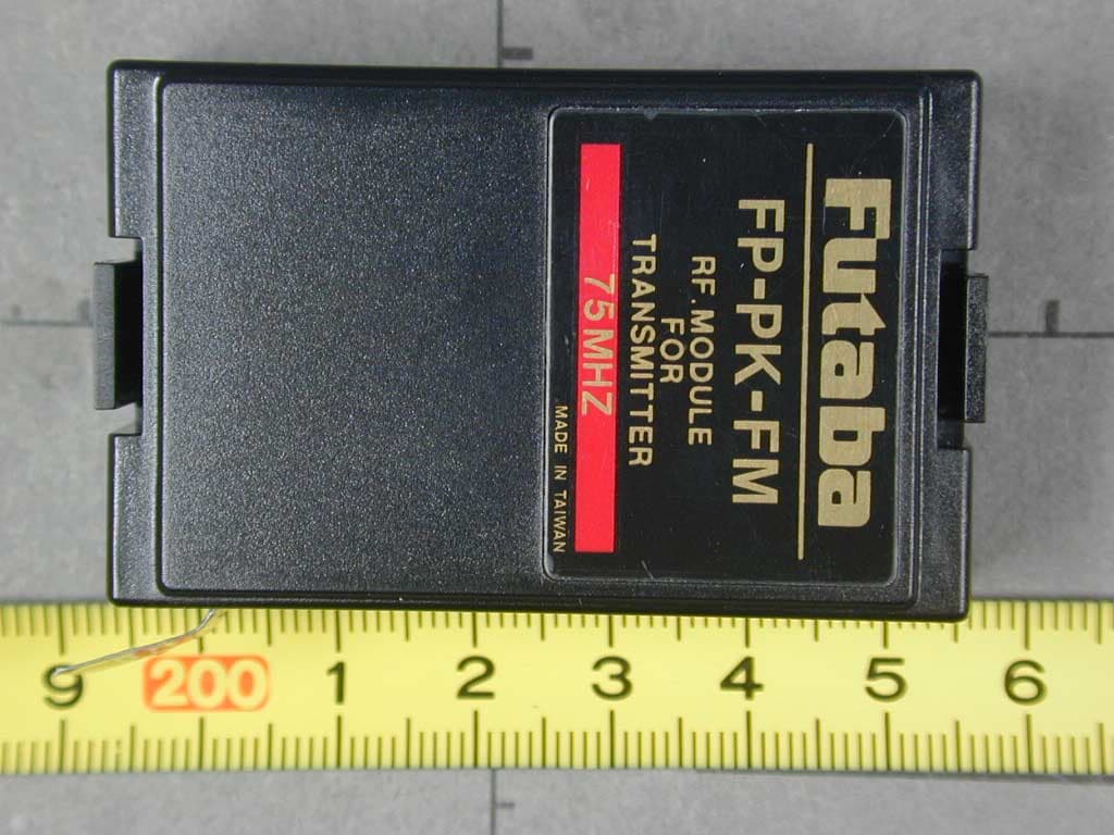
Click to zoom
Application Details
- Equipment Class
- TNB - Licensed Non-Broadcast Station Transmitter
- Date of Grant
- Nov 11, 2002
- Application Purpose
- Original Equipment
- Date of Application
- Nov 11, 2002
- Equipment Note
- 3 Channel Radio Control Transmitter
- Frequency Range
- 75.59000000 - 75.59000000
- Company
- Futaba Corporation
- Country
- Japan
Documents & Files
Document Text
Text extracted from the exhibit documents filed with the FCC. Open a document above to read the original.
Users Manual
3PK 3-CHANNEL RADIO CONTROL SYSTEM INSTRUCTION MANUAL Futaba© Digital Proportional R/C System Technical updates and additional programming examples available at: http://www.futaba-rc.com/faq/faq-3pk.html FUTZ8533 for FUTJ32**/33** V1.0 Entire Contents © Copyright 2002 3PK with Optional Accessory Offset Adapter Installed 2 Transmitter Controls Antenna Digital trim 2 (DT2) (default throttle trim) Edit buttons Steering wheel LCD screen Push switch 1 (PS1) Power switch CAMPac Digital trim 3 (DT3) Pilot lamp Digital Dial 3 (DL3) (default CH3 knob) Mechanical ATL adjusting screw Throttle trigger Digital trim 1 (DT1) (default steering trim) (See page 9 for operating instructions.) (See page 50 for the adjustment instructions.) (See page 9 for operating instructions.) (See page 9 for operating instructions.) (See page 12 for instructions to change colors.) Grip Handle Push switch 3 (PS3) Display switch Digital Dial 1 (DL1) (default steering dual rate) (See page 9 for the operating instructions.) Push switch 2 (PS2) Digital Dial 2 (DL2) (default ATL) (See page 9 for the operating instructions.) Sound port Use a commercial earphone with a 3.5mm diameter plug. *The switches, knobs and trimmers may all be reassigned. (see pp. 34-35) Precautions when turning the power switch on and off. When the data is changed using the edit keys or trim levers, wait at least two seconds before turning off the power. If the power is turned off within two seconds after the data was changed, the new data will not be written to memory. Charge Port DSC Port DEFAULT ASSIGNMENT TABLE The factory default functions activated by the switches and knobs are shown below. Default assignments may be changed using the FUNC-DIAL and FUNC-SW programming (See pp. 34-35.) Features assigned to DL1, 2, 3, and DT1, 2, 3 are displayed at all times on right side of LCD screen. CONTROLDEFAULT DT1Steering trim DT2Throttle trim DT3NONE DL1Steering dual rate DL2ATL DL3Channel 3 PS1NONE PS2NONE PS3NONE INTRODUCTION • Transmitter Controls and Defaults .................................2 • Owner’s Manual and Additional Technical Help ..........4 • Support and Service .......................................................4 • Contents and Technical Specifications ..........................5 • Optional Accessories......................................................5 • A Quick Introduction to the 3PK System ......................6 • Getting to Know the Transmitter ...................................8 • Display Switch .......................................................8 • Digital Trim Operation...........................................9 • Digital Grip Dial Operation ...................................9 • Installation....................................................................10 PROGRAMMING..........................................................11 • Menu Selection Overview............................................11 • Direct Selection Menu Overview.................................11 • LV1Functions ...............................................................12 • Level Selection LEVEL-SEL...................................12 • System Settings SYSTEM.......................................13 • Backlighting LHT-MODE............................13 • Backlighting time LHT-TIME.......................13 • LCD contrast CONTRAST............................13 • Buzzer tone BUZ-TONE...............................13 • LED pilot lamp LED-MODE........................13 • Home screen display DISPL-SEL................13 • Model Selection MDL-SEL ....................................14 • Model Name MDL-NAME......................................15 • User Name (set within MDL-NAME) ..........15 • Modulation MOD-MODE........................................16 • Failsafe and Battery Failsafe FAIL-SAFE...............17 • Servo Reversing CH-REV.......................................18 • End Point Adjustment CH-EPA.............................18 • Exponential ST-EXP, TH-EXP..................................20 • Sub-Trim SUB-TRIM..............................................22 • LV2Functions ...............................................................23 • Speed ST-SPEED, TH-SPEED...................................23 • ABS ABS...............................................................24 • Throttle Acceleration TH-ACCEL...........................26 • Idle-up IDLE-UP.....................................................27 • Auto-Start/Engine Cut AT-START..........................28 • Timer TIMER.........................................................30 • Lap List LAP-LIST..................................................31 • Model Reset MDL-RES..........................................32 • Model Copy MDL-COPY........................................33 • Function FUNC-SW, FUNC-DIAL..............................34 • Direct Selection Menu Options DIRC-CALL..........36 • LV3Functions ...............................................................37 • Throttle Electronic ATLTH-ATL............................37 • Steering Dual Rates ST-D/R.................................38 • Servo Display SERVO............................................39 • Channel 3 Position CH3-POSI...............................40 • Programmable Mixes PRG-MIX1, PRG-MIX2.........40 • Brake Mix BRAKE-MIX..........................................42 • Boat Mode BOAT-MODE........................................43 • MC Setup MC-SETUP............................................44 • Adjuster ADJUSTER...............................................45 APPENDICES................................................................46 • Appendix I - Precautions and Warnings ......................46 • Application, Export and Reconstruction..............46 • Liability and Warranty .........................................46 • Battery Recycling.................................................46 • Meaning of Special Markings ..............................47 • Safety Precautions (DO NOT operate without reading) ...…
Text truncated - open the document above for the full version.
Users Manual
• Response direction: • Normal or reversed for all dials/trimmers, and switch 3. • Normal or alternate for switches 1 and 2. INTERACTION: • If multiples switches/dials/trims are assigned to do the same job, their settings are combined up to the limits of the function. For example, assigning steering trim to both DT1 and DL1 means moving either adjusts the trim from the current position up to the maximum available trim. (Total trim available is still the same, not doubled.) • Digital: Since the dials and trims are digital, their physical position does not matter to the model memory. If a dial or trim is bumped when both switches are off, no change is made to the position remembered in the memory. For example, turn on the display. Note the steering trim position shown on screen. Turn the display off. With the display off, press the digital trims. Now turn the display back on. Note that the trim has not changed. The same is true for the digital dials, meaning no more need to try to “store” or “set” the dial positions before changing model memories to avoid unintentional changes in your other models! DESIRED END RESULT:Create driver-specific setups for each car for easy adjustment of features on-the-fly. CAUTION: Be sure you know what each switch/dial/trim is doing prior to every operation. 35 GOAL: Assign idle-up to the push button switch on the radio’s handle (SW2 aka PS2), while using LV2menus. (If using LV3, select FUNC-SWfrom menu 2.) (If using LV1, first change level selection to LV2, p. 12.) Assign throttle acceleration forward side to grip dial 1 and brake side to grip dial 2. Adjust steps to 1% for very fine adjustments. Where Next: STEPS: Open and select menu 2. Select FUNC-SW. Select switch #2 (SW2 aka PS.2). Set function to idle-up. Reverse switch direction to have idle-up on unless button is held. Close function and menu. Open and select menu 2. Select FUNC-DIAL. For dial 1, select acceleration forward. Set step to 1%. Select dial 2, acceleration braking. Set step to 1%. Reverse dial direction so turning dial 2 backward increases braking side of acceleration, turning dial 1 forward increases throttle side acceleration. Close function and menu. INPUTS: to SW2. to IDLE-UP. to ALT. 9 times to ACC-F. to 1. 9 times to ACC-B. to 1. Use servo screen to see effectiveness of dial/switch changes (SERVO) (LV3): See p. 39. Set up throttle acceleration (TH-ACCEL): See p. 26. Set up ABS (ABS): See p. 24. Set up servo speed (ST-SPEED, TH-SPEED): See p. 23. Set up tilt mixing (BOAT-MODE) (LV3): See p. 43. Set up brake mixing (BRAKE-MIX) (LV3): See p. 42. Let’s do a dial setup now. 36 Direct Selection Menu Options DIRC-CALLLevelsLV2, LV3 Only DEFINITION: Customize what functions are available at the push of 2 buttons (Direct menu and one more) by adjusting the Direct Selection menu. Note that direct menu selection/exit is always the DIR button. AVAILABLE FOR: N/A. ADJUSTABILITY: All functions are assignable to the 6 available buttons. INTERACTION: None. DESIRED END RESULT:2-button access to the 6 most frequently used functions, such as model selection, timer, auto-start (to reset for next use) or other functions you are currently fine-tuning for your model. CAUTION: The direct button opens the direct selection menu and closes it again, regardless of where you are in the programming. That function can not be assigned elsewhere, and nothing else can be assigned to that key. GOAL: Customize direct select menu so button 1 opens auto-start and button 6 goes to timer, while using LV2. (If using LV3, select DIRC-CALLfrom menu 3.) (If using LV1, first change level selection to LV2, p. 12.) Where Next: STEPS: Open and Select menu 2. Select DIRC-CALL. Edit button 1 to auto-start. Select button 6. Edit button 6 to timer. Close function and menu. Press direct key to open direct menu. Select Auto-start. Return to direct menu. Close menu. INPUTS: to AT-START. 11 times to TIMER. Change switch assignments (FUNC-SW): See p. 34-35. Change dial assignments (FUNC-DIAL): See p. 34-35. LV3FUNCTIONS for the Expert Driver, Boats or Complex Models LevelLV3 OnlyProgramming Adjustment of Throttle ATL ATL DEFINITIONS: • ATL, electronic: (Adjustable throttle limiter) Adjusts total travel available to the braking side of the throttle servo, similar to adjusting EPA, but allows adjustment “on the fly” when ATL is assigned to a dial. When brake mixing is used in the unmixed mode, this adjusts the rear brake servo without changing amount of braking to front brake servo. • ATL, mechanical: Decreases the physical distance the brake trigger can move. See p. 51. AVAILABLE FOR: Braking only. ADJUSTABILITY: • RATE: 0 (no braking at all) to 100% (same as EPA). Default: 100%. • Rate adjustment: May be easily adjusted while driving (if assigned to a dial/trim, see FUNC-DIAL, pp. 34-35). Default assignment is to gripper dial 2. INTERACTION:EPA affects total travel available to the servo. ATL is directly proportional to EPA. DESIRED END RESULT:Quickly adjust overall braking sensitivity, including with a dial while driving on the track. CAUTION: Dial 2 is assigned for ATL adjustment as a default, even if user does not realize it. 37 GOAL: While using LV3: • Reassign the ATL adjustment to digital trim 1; • Adjust the ATL setting from 100% to 20% (with the digital trim centered). (If using LV1or LV2, first change level selection, see p. 12.) Where Next: STEPS: Use FUNC-DIALto assign ATL to digital trim 1. While viewing home screen, adjust digital trim 1 until ATL reads 0. Select ATL. Adjust ATL to 20%. Close function and menu. INPUTS: 9 steps to DT1. to ATL. Move trim 1, if necessary, until display reads 0for ATL. to 20%. Adjust the throttle servo’s EPA (EPA):See p. 18. Set up channel 3 control (CH3-POSI):See p. 40. Set up brake mixing for separate front/rear brakes (BRAKE-MIX):See p. 42. Set up tilt mixing for boats (BOAT-MODE):See p. 43. Steering Dual Rate ST-D/RLevelLV3 Only DEFINITIONS: • Dual Rate, or primary dual rate: Decreases the ve…
Text truncated - open the document above for the full version.
Cover Letter(s)
American Telecommunications Certification Body Inc. 6731 Whittier Ave, McLean, VA 22101 September 22, 2002 RE: FUTABA Corporation of American FCC ID: AZPFP-PK-FM-75 After a review of the submitted information, I have a few comments on the above referenced Application. 1) Although the label information shows the label attached to the product, it is not obvious what part of the device the label is placed upon. Please provide additional photographs or drawing to help show where the label is placed. 2) Please provide information regarding DC voltages/currents applied into the several elements of the final radio frequency amplifying device for normal operation over the power range? 3) Please provide front and back photograph of the daughter board attached to the TX board. 4) From the Internal photographs, it is not certain where the TX board was located inside the device. Please provide further information 5) One page of the schematics is not easily readable. Are these part of the TX circuitry? If so, please provide a better copy. 6) The crystal appears to be accessible from the outside of the device from the external photographs. This is not allowed. Please see 95.645. Please explain. 7) The users manual page 15 & 20 shows the crystal location to the user as accessible. However, part 95.645(b) does not allow this. Please explain. 8) Page 20 & 100 mentions that the crystal may be changed without removal of the module. This is not allowed according to 95.645(b). 9) Currently, the application only appears to be submitted for 75.590 MHz. Information regarding additional modules, test data, or any other necessary information does not appear to be provided. This information must be provided with this application (see 95.645(b)) or this application will only cover a single frequency. If this application will nly cover a single application, then the users manual should be modified to cover this. Please comment and provide any necessary information. Note Users Manual, page 99. 10) Please provide an explanation for the large difference between radiated and conducted power measurements. Timothy R. Johnson Examining Engineer Direct Phone: 404-414-8071 mailto: [email protected] The items indicated above must be submitted before processing can continue on the above referenced application. Failure to provide the requested information may result in application termination. Correspondence should be considered part of the permanent submission and may be viewed from the Internet after a Grant of Equipment Authorization is issued. Please do not respond to this correspondence using the email reply button. In order for your response to be processed expeditiously, you must submit your documents through the AmericanTCB.com website. Also, please note that partial responses increase processing time and should not be submitted. Any questions about the content of this correspondence should be directed to the sender.
Cover Letter(s)
EMV-Pr ̧fzentrum EMI/EMC-Testcenter Coordinates: ƒussere Fr ̧hlingstrasse 45 ! D-94315 Straubing Telefon (0 94 21) 55 22-0 Telefax (0 94 21) 55 22-99 [email protected] ! http://www.senton.de Senton GmbH ! ƒussere Fr ̧hlingstrasse 45 ! D-94315 Straubing Timothy R. Johnson American TCB 2002-11-04 In reference to FCC ID AZPFP-PK-FM-75 1. The position of the label has been modified. It is now on top of the RF module and visible from outside. 2. DC Voltage/Current supplied to the final RF amplifier is 9.6 V DC / 66.3 mA. 3. The internal photographs have been amended accordingly and will be uploaded. 4. The position of the TX module is further illustrated by additional external and internal photos. 5. Only the first page shows the RF circuitry. 6. We had a preproduction sample for testing on which the crystal was accessible. This has been changed for production. 7. The user manual has been corrected accordingly. The corrected version will be uploaded. 8. Same as 7. 9. This application covers only 75.590 MHz as single frequency. No other information was received from the client and the users manual has been modified accordingly. 10. Since radiated emission tests have been with the unit standing on a wooden table, there is no counterweight for the antenna. This reduces dramatically the ERP of the transmitter and explains this significant difference between conducted and radiated data. Johann Roidt Senton GmbH
External Photos
FCC ID: AZPFP-PK-FM-75 External Photos Page 1 of 6 FCC ID: AZPFP-PK-FM-75 External Photos Page 2 of 6 FCC ID: AZPFP-PK-FM-75 External Photos Page 3 of 6 FCC ID: AZPFP-PK-FM-75 External Photos Page 4 of 6 FCC ID: AZPFP-PK-FM-75 External Photos Page 5 of 6 FCC ID: AZPFP-PK-FM-75 External Photos Page 6 of 6
External Photos
FCC ID: AZPFP-PK-FM-75 External Photos Page 1 of 7 FCC ID: AZPFP-PK-FM-75 External Photos Page 2 of 7 FCC ID: AZPFP-PK-FM-75 External Photos Page 3 of 7 FCC ID: AZPFP-PK-FM-75 External Photos Page 4 of 7 FCC ID: AZPFP-PK-FM-75 External Photos Page 5 of 7 FCC ID: AZPFP-PK-FM-75 External Photos Page 6 of 7 FCC ID: AZPFP-PK-FM-75 External Photos Page 7 of 7
Internal Photos
FCC ID: AZPFP-PK-FM-75 Internal Photos Page 1 of 4 FCC ID: AZPFP-PK-FM-75 Internal Photos Page 2 of 4 FCC ID: AZPFP-PK-FM-75 Internal Photos Page 3 of 4 FCC ID: AZPFP-PK-FM-75 Internal Photos Page 4 of 4
Internal Photos
FCC ID: AZPFP-PK-FM-75 Internal Photos Page 1 of 2 FCC ID: AZPFP-PK-FM-75 Internal Photos Page 2 of 2
Test Report
EMV-Pr ̧fzentrum EMI/EMC-Testcenter FCC-ID: AZPFP-PK-FM-75 Test Report No. 55503-20391 Page 1 of 55 Pages Straubing, July 03 2002 T E S T - R E P O R T No. 55503-20391 for T3PK FM R/C Transmitter Variant covered by this test report: PF-FM75 Applicant: Futaba Corporation Purpose of testing: To show compliance with - FCC Code of Federal Regulations, CFR 47, Part 95 - FCC Code of Federal Regulations, CFR 47, Part 2, Subpart J Note: The test data of this report relate only to the individual item which has been tested. This report shall not be reproduced except in full extent without the written approval of the testing laboratory. EMV-Pr ̧fzentrum EMI/EMC-Testcenter FCC-ID: AZPFP-PK-FM-75 Test Report No. 55503-20391 Page 2 of 55 Pages Table of Contents 1. Administrative Data ............................................................................................. 3 2. Identification of Test Laboratory .......................................................................... 4 3. Summary of Test Results .................................................................................... 5 4. Operation Mode of EUT....................................................................................... 6 5. Configuration of EUT and Peripheral Devices ..................................................... 7 6. Measuring Methods ............................................................................................. 8 6.1. Maximum Transmitter Power (ß95.639)........................................................ 8 6.2. Frequency tolerance (ß95.623)................................................................... 10 6.3. Emission Bandwidth (ß95.633) ................................................................... 12 6.4. Unwanted Emission 30 MHz - 1 GHz (ß95.635, ß95.639)........................... 13 7. Photographs of Test Setups .............................................................................. 15 8. Equipment List................................................................................................... 17 9. Referenced Regulations .................................................................................... 19 10. List of Measurements ........................................................................................ 20 11. Test Results ...................................................................................................... 21 12. Additional Results.............................................................................................. 31 EMV-Pr ̧fzentrum EMI/EMC-Testcenter FCC-ID: AZPFP-PK-FM-75 Test Report No. 55503-20391 Page 3 of 55 Pages 1. Administrative Data Equipment Under Test (EUT): T3PK FM Variant covered by this report: PF-FM75 Serial number(s): 001 Type of equipment: R/C Transmitter Type of emission: F1D Parts/accessories: --- FCC-ID: AZPFP-PK-FM-75 Applicant: Futaba Corporation (full address) R/C Engineering Unit 1 1080, Yabutsuka Chosei-son, Chosei-gun, Chiba-ken, 299-4395 Japan Contract identification: --- Contact person: Mr. Fujita Manufacturer: Futaba Corporation Receipt of EUT: June13, 2002 Dates of test: June 19 to 29, 2002 Note: --- Responsible for testing: Thomas Eberl Responsible for test report: Thomas Eberl EMV-Pr ̧fzentrum EMI/EMC-Testcenter FCC-ID: AZPFP-PK-FM-75 Test Report No. 55503-20391 Page 4 of 55 Pages 2. Identification of Test Laboratory Test Laboratory: Senton GmbH EMI/EMC Test Center (full address): Aeussere Fruehlingstrasse 45 D-94315 Straubing Germany Contact person: Mr. Johann Roidt Communication: Telephone (+49) 0 94 21 / 55 22-0 Fax (+49) 0 94 21 / 55 22-99 eMail: [email protected] FCC registration number: 90926 Industry Canada file number: IC 3050 EMV-Pr ̧fzentrum EMI/EMC-Testcenter FCC-ID: AZPFP-PK-FM-75 Test Report No. 55503-20391 Page 5 of 55 Pages 3. Summary of Test Results The tested sample complies with the requirements for set forth in the The Code of Federal Regulations 47, Part 95, Subpart C & E and The Code of Federal Regulations 47 Part 2, Subpart J. of the Federal Communication Commission (FCC). Johann Roidt Thomas Eberl Technical Manager Test Engineer EMV-Pr ̧fzentrum EMI/EMC-Testcenter FCC-ID: AZPFP-PK-FM-75 Test Report No. 55503-20391 Page 6 of 55 Pages 4. Operation Mode of EUT • transmitting continuously 1 • with accu pack supply nominal 9.6 V DC) 2 • antenna extended to maximum 3 • operating with f = 75.590 MHz For conducted measurements a dummy load was used as delivered by applicant. A short description of the circuit and the method to stop modulation can be found in the following figure. 1 Modulation as indicated on appropriate test record 2 For conducted measurements replaced by external DC supply 3 For radiated emissions only EMV-Pr ̧fzentrum EMI/EMC-Testcenter FCC-ID: AZPFP-PK-FM-75 Test Report No. 55503-20391 Page 7 of 55 Pages 5. Configuration of EUT and Peripheral Devices EUT is configured as stand-alone device Configuration of cables of EUT Not applicable Configuration of peripheral devices connected to EUT Not applicable EMV-Pr ̧fzentrum EMI/EMC-Testcenter FCC-ID: AZPFP-PK-FM-75 Test Report No. 55503-20391 Page 8 of 55 Pages 6. Measuring Methods 6.1. Maximum Transmitter Power (ß95.639) The maximum transmitter power was measured conducted and radiated. 6.1.1. Conducted Maximum Transmitter Power A spectrum analyzer / EMI test receiver was connected to the output of the transmitter power amplifier (conducted measurement) via dummy load while EUT was operating in transmit mode using the assigned frequency. The trace mode of the spectrum analyzer was set to max hold with: RBW = 100 kHz, VBW = 100 kHz, span = 1 MHz, sweep = 20 ms (auto mode) See figure 1 for the measurement setup. Test equipment used (see equipment list for details): 02, 18, 51, 69, 70, 71 5 8 3 1 6 4 7 2 Figure 1: Measurement setup for testing on antenna connector 1 Transmitter (EUT) 5 Test cable 2 Dummy load 6 DC-block 3 Wooden table 7 Attenuator 4 DC power supply 8 Spectrum analyzer EMV-Pr ̧fzentru…
Text truncated - open the document above for the full version.
Test Setup Photos
EMV-PrüfzentrumEMI/EMC-Testcenter FCC-ID: AZPFP-PK-FM-75Test Report No. 55503-20391 Page 15 of 55 Pages 7.Photographs of Test Setups Test setup unwanted radiation 30 MHz - 1 GHz EMV-PrüfzentrumEMI/EMC-Testcenter FCC-ID: AZPFP-PK-FM-75Test Report No. 55503-20391 Page 16 of 55 Pages Test setup unwanted radiation 30 MHz - 1 GHz (continued)
Contact Information
Applicant
Toshikazu Hama(Manager)
Technical Contact
Senton GmbHJohann Roidt
[email protected]+49 9421 55 22 13
Aeussere Fruehlingstrasse 45 · Straubing · Germany
Non-Technical Contact
Senton GmbHJohann Roidt
[email protected]+49 9421 55 22 13
Test Firm
TUV SUD Product Service GmbH PS-EMC-STRRainer Heller
Technical Specifications
| # | Rule Parts | Frequency Range | Power Output | Emission | Tolerance |
|---|---|---|---|---|---|
| 1 | 95C | 75.59 MHz - 75.59 MHz | 338.00 mW | 6K06F1D | 0.0010000000 % |
Other Applications from Futaba Corporation

AZP-FEX11T
Jan 22, 20262.4GHz band Module
Equipment Class
DSS - Part 15 Spread Spectrum Transmitter
AZPCGY770R-24G
Aug 19, 2024Radio Control
Equipment Class
DTS - Digital Transmission SystemAZPTM18
Jan 21, 2024Radio Control
Equipment Class
DSS - Part 15 Spread Spectrum TransmitterAZPR9001SB
Jan 17, 2024Radio Control
Equipment Class
DSS - Part 15 Spread Spectrum Transmitter
AZPR7201SB-24G
Jan 14, 2024Receiver
Equipment Class
DTS - Digital Transmission System