AZPFS0005HUSB Interlink Controller
Futaba Corporation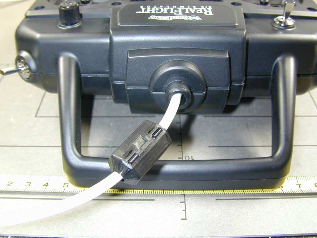
Click to zoom
Application Details
- Equipment Class
- JBP - Part 15 Class B Computing Device Peripheral
- Date of Grant
- Mar 23, 2002
- Application Purpose
- Original Equipment
- Date of Application
- Mar 23, 2002
- Equipment Note
- USB Interlink Controller
- Company
- Futaba Corporation
- Country
- Japan
Documents & Files
Document Text
Text extracted from the exhibit documents filed with the FCC. Open a document above to read the original.
Users Manual
Contents Chapter 1. Introduction 1 Introduction...............................................................................................................................1 What's New in Generation 2 with USB InterLink Controller ....................................................1 USB InterLink Controller............................................................................................2 Menu-Driven Interface................................................................................................2 Additional New Features.............................................................................................2 Chapter 2. Before You Begin 5 System Requirements................................................................................................................5 Video and Sound Cards ............................................................................................................. 6 Getting the Most out of RealFlight............................................................................................6 Chapter 3. Getting Started 9 Overview...................................................................................................................................9 Installing RealFlight G2............................................................................................................9 Program Installation..................................................................................................10 Using Your Own R/C Radio to Control RealFlight (Optional).................................12 Exploring RealFlight G2.......................................................................................................... 13 Start the Program.......................................................................................................13 The RealFlight Main Display....................................................................................14 Choosing Your Aircraft.............................................................................................17 Changing Airport.......................................................................................................19 Some Common Tasks................................................................................................21 Creating a Viewport..................................................................................................21 Using Gadgets...........................................................................................................22 Virtual Flight Instructor..............! Airport Editing..........................................................................................................24 Where to Go from Here...........................................................................................................28 Chapter 4. Using RealFlight G2 29 Introduction.............................................................................................................................29 Program Features.....................................................................................................................29 Controller Features..................................................................................................................33 Graphics and Sound Quality....................................................................................................33 Technical Support....................................................................................................................34 Chapter 5. The InterLink Controller 35 The InterLink Controller—Designed for R/C..........................................................................35 Start Flying!.............................................................................................................................36 Joystick vs. Interface Mode.....................................................................................................37 The InterLink Controller (Joystick Mode)...............................................................................38 The InterLink Controller (Interface Mode)..............................................................................38 Two ways to use Interface Mode...............................................................................38 Interface Mode: Joystick Emulation Interface .........................................................................39 Calibration vs. Interface Wizard................................................................................40 Interface Calibration ..................................................................................................40 Interface Wizard ........................................................................................................41 Interface Mode: Direct Control Interface.................................................................................42 Before you use the Direct Control Interface ..............................................................42 Setting the Direct Control Interface...........................................................................42 Mapping channels to Servos ......................................................................................42 Swapping Aircraft that use Direct Control Interface .................................................44 InterLink Controller Hints and Tips.........................................................................................44 What if my transmitter has fewer than eight channels? .............................................44 When to use the Interface Wizard, and when to use the Software Radio or Servo page ...........................................................................................................................45 What about previous versions of RealFlight? ............................................................45 Chapter 6. The Airport Menu 47 Airport Menu Overview.......…
Text truncated - open the document above for the full version.
Cover Letter(s)
Request for Confidentiality March 08, 2002 American Telecommunications Certification Body, Inc. 6731 Whittier Avenue Suite C110 McLean, VA 22101 RE: Certification Application FCC ID: AZPFS0005H Please be advised that the following information is to be held confidential and behalf of Futaba Corporation: • Block Diagram • Schematics The application contains technical information which Futaba Corporation deems to be trade secrets and proprietary. If made public, the information might be used to the disadvantage of the applicant in the market place. Thank you for your attention to this matter. Signatory Johann Roidt
External Photos
FCC ID AZPFS0005H External Photos
ID Label/Location Info
FCC ID AZPFS0005H Label Information
Internal Photos
FCC ID AZPFS0005H Internal Photos
Test Report
Page 1 of 44 Pages EMI/EMC-TestcenterEMV-Pr ̧fzentrum Straubing, December 12, 2001 T E S T - R E P O R T No. 55503-10715 for Interlink Flight Simulator Applicant:Futaba Corporation Purpose of testing:To show compliance with FCC Code of Federal Regulations, Part 15 Subpart B Class B Industry Canada Radio Standards Specification RSS-210 Issue 2, Section 6.1 (Category I Equipment) Note: The test data of this report relate only to the individual item which has been tested. This report shall not be reproduced except in full extent without the written approval of the testing laboratory. Test report for FCC Part 15 Subpart BTest Report No. 55503-10715 Page 2 of 44 Pages EMI/EMC-TestcenterEMV-Pr ̧fzentrum Table of Contents 1. Administrative Data ..............................................................................................3 2. Identification of Test Laboratory ...........................................................................4 3. Summary of Test Results.....................................................................................5 4. Operation Mode of EUT .......................................................................................6 5. Configuration of EUT and Peripheral Devices ......................................................7 6. Measuring Methods..............................................................................................8 6.1. Conducted Emission 0.45 MHz - 30 MHz (ß15.107) / RSS-210 Section 7.4) ...................................................................................................8 6.2. Radiated Emission 30 MHz - 1 GHz (FCC ß15.109 / RSS-210 Section 7.3) .................................................................................................10 7. Equipment List ...................................................................................................14 8. Photographs Taken During Testing....................................................................16 9. List of Measurements.........................................................................................20 9.1. List of Measurements According To FCC Part 15 Subpart B.......................21 9.2. List of Measurements According To Industry Canada RSS- 210 22 10. Referenced Regulations.....................................................................................23 11. Test Results .......................................................................................................24 Test report for FCC Part 15 Subpart BTest Report No. 55503-10715 Page 3 of 44 Pages EMI/EMC-TestcenterEMV-Pr ̧fzentrum 1.Administrative Data Equipment Under Test (EUT):Interlink Serial number(s):--- Type of equipment:Flight Simulator Parts/accessories:--- FCC-ID:--- Applicant:Futaba Corporation. (full address)1080, Yabutsuka Chosei-mura, Chosei-gun, Chiba-ken 299-4395 Japan Contract identification:--- Contact person:Mr. Kanetsuna Manufacturer:Futaba Corporation Receipt of EUT:October 30, 2001 Date of test:November 28 to 30, 2001 Note:--- Responsible for testing:Karl Roidt Responsible for test report:Karl Roidt (cj) Test report for FCC Part 15 Subpart BTest Report No. 55503-10715 Page 4 of 44 Pages EMI/EMC-TestcenterEMV-Pr ̧fzentrum 2.Identification of Test Laboratory Test Laboratory:Senton GmbH EMI/EMC Test Center (full address):Aeussere Fruehlingstrasse 45 D-94315 Straubing Germany Contact person:Mr. Johann Roidt Communication:Telephone(+49) 0 94 21 / 55 22-0 Fax (+49) 0 94 21 / 55 22-99 eMail:[email protected] FCC registration number:90926 Industry Canada file number:IC 3050 Test report for FCC Part 15 Subpart BTest Report No. 55503-10715 Page 5 of 44 Pages EMI/EMC-TestcenterEMV-Pr ̧fzentrum 3.Summary of Test Results The tested sample complies with the limits forth in the Code of Regulations FCC Part 15 Subpart B Class B of the Federal Communication Commission (FCC). and the Radio Standards Specification RSS-210 Issue 2, Section 6.1 for Low Power Licence-Exempt Radiocommuniction Devices of Industry Canada. Johann RoidtKarl Roidt Technical ManagerTest Engineer Test report for FCC Part 15 Subpart BTest Report No. 55503-10715 Page 6 of 44 Pages EMI/EMC-TestcenterEMV-Pr ̧fzentrum 4.Operation Mode of EUT normal usuage Test report for FCC Part 15 Subpart BTest Report No. 55503-10715 Page 7 of 44 Pages EMI/EMC-TestcenterEMV-Pr ̧fzentrum 5.Configuration of EUT and Peripheral Devices Configuration of cables of EUT --- Configuration of peripheral devices connected to EUT PCDell Dimension 4100 monitorSiemens MCM 174S26361-12575-V150 mouseMicrosoft PS2 ITE 78CJ printer parallelHP Think Jet 2225D+ # Inv. no. C-1240 printer serialHP Think Jet 2225D+ # Inv. no. C-1237 Test report for FCC Part 15 Subpart BTest Report No. 55503-10715 Page 8 of 44 Pages EMI/EMC-TestcenterEMV-Pr ̧fzentrum 6.Measuring Methods 6.1.Conducted Emission 0.45 MHz - 30 MHz (ß15.107) / RSS-210 Section 7.4) Conducted emissions were measured in the frequency range 0.45 MHz to 30 MHz. The bandwidth of the EMI-Receiver was set to 9 kHz and the detector-function was set to CISPR quasi-peak. The test setup was made in accordance with ANSI C63.4-1992. Measurements were performed on phase and neutral lines of the power-cords of the tested system. Preliminary scans were taken with the detector-function of the EMI- receiver set to peak to determine the conducted EMI-profile of the EUT. At the final test the cables and equipment were placed and moved within the range of positions likely to find their maximum emissions. See figure 1 for the measurement setup. Test equipment used (see equipment list for details): 04, 22, 23, 60, 63 Test report for FCC Part 15 Subpart BTest Report No. 55503-10715 Page 9 of 44 Pages EMI/EMC-TestcenterEMV-Pr ̧fzentrum 10 11 6 2 5 1 34 7 8 9 Figure 1: Measurement setup for conducted emission test 1 EUT 8 LISN for PC 2 Parallel Printer 9 LISN for peripheral device(s) 3 PC 10 Test receiver 4 Monitor 11 Shielded room 5 Serial Printer 6 Keyboard 7 Mouse Test report for FCC Part 15 …
Text truncated - open the document above for the full version.
Test Setup Photos
Test report for FCC Part 15 Subpart BTest Report No. 55503-10715 Page 17 of 44 Pages EMI/EMC-TestcenterEMV-Pr ̧fzentrum Photos No. 8.1 Test setup for conducted emission test 450 kHz - 30 MHz Test report for FCC Part 15 Subpart BTest Report No. 55503-10715 Page 18 of 44 Pages EMI/EMC-TestcenterEMV-Pr ̧fzentrum Photos No. 8.2 Test setup for radiated emission pre-test 30 MHz - 1 GHz (semi anechoic room) and final test 1 GHZ - 2 GHz Test report for FCC Part 15 Subpart BTest Report No. 55503-10715 Page 19 of 44 Pages EMI/EMC-TestcenterEMV-Pr ̧fzentrum Photos No. 8.3 Test setup for radiated emission final test 30 MHz - 1 GHz (open area test site)
Contact Information
Applicant
Toshikazu Hama(Manager)
Technical Contact
Senton GmbHJohann Roidt
[email protected]49 9421 55 22 13
Aeusserre Fruehlingstrasse 45 · Straubing · Germany
Test Firm
TUV SUD Product Service GmbH PS-EMC-STRRainer Heller
Technical Specifications
| # | Rule Parts | Frequency Range | Power Output |
|---|---|---|---|
| 1 | 15B | - | - |
Other Applications from Futaba Corporation

AZP-FEX11T
Jan 22, 20262.4GHz band Module
Equipment Class
DSS - Part 15 Spread Spectrum Transmitter
AZPCGY770R-24G
Aug 19, 2024Radio Control
Equipment Class
DTS - Digital Transmission SystemAZPTM18
Jan 21, 2024Radio Control
Equipment Class
DSS - Part 15 Spread Spectrum TransmitterAZPR9001SB
Jan 17, 2024Radio Control
Equipment Class
DSS - Part 15 Spread Spectrum Transmitter
AZPR7201SB-24G
Jan 14, 2024Receiver
Equipment Class
DTS - Digital Transmission System