AZPFS006HUSB Flight Controller
Futaba Corporation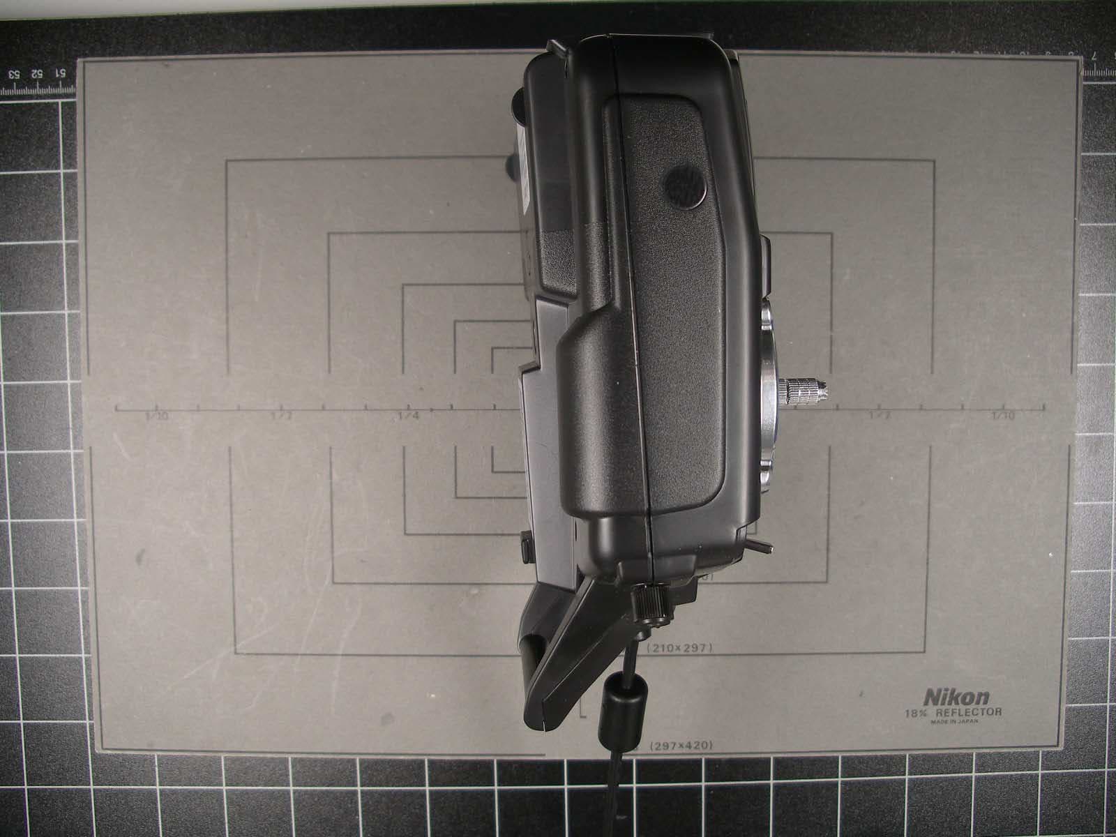
Click to zoom
Application Details
- Equipment Class
- JBP - Part 15 Class B Computing Device Peripheral
- Date of Grant
- Oct 24, 2007
- Application Purpose
- Original Equipment
- Date of Application
- Oct 24, 2007
- Equipment Note
- USB Flight Controller
- Company
- Futaba Corporation
- Country
- Japan
Documents & Files
Document Text
Text extracted from the exhibit documents filed with the FCC. Open a document above to read the original.
Users Manual
GREAT PLANES RealFlight Generation 4 and the InterLink Elite Controller © Great Planes Model Manufacturing Company P.O. BOX 788, Urbana, IL 61801 Table of Contents Introduction 1 RealFlight G4 Feature Highlights 2 How to read this manual 5 Before You Begin 7 System Requirements 7 Video and Sound Cards 8 Getting the Most out of RealFlight 9 Getting Started 11 Installing RealFlight G4 11 Using Your Own R/C Radio 15 Exploring RealFlight G4 17 Where to Go From Here 31 The InterLink Elite Controller 33 Start Flying! 34 The Simulation Menu 37 Select Airport... 38 Edit Current Airport... 40 Utilizing the Editor 52 Create New Airport 58 Capture Screenshot 58 Mute/Unmute Audio 59 Environment 60 Flight Failures 65 Import 68 Export 70 Manage User Files 73 Settings 75 Exit 105 Airport MRU 106 The Aircraft Menu 107 Aircraft Selection... 108 Edit Current Aircraft 111 Select Color Scheme 123 Save Color Scheme As... 124 Remember Aircraft Position 127 Clear Aircraft Position 128 Reset Position 129 Kill Engine 129 Aircraft MRU 130 Controller Menu 133 Select Controller 134 Controller Calibration 135 Channel Mapping... 137 Joystick Mode vs. Transmitter Mode 140 InterLink Elite Controller (Joystick Mode) 140 InterLink Elite Controller (Transmitter Mode) 141 Transmitter Mode: Joystick Emulation Interface 143 Transmitter Mode: Pass Through Interface 144 InterLink Elite Controller Tips 145 Events Menu 147 Autorotation/Deadstick 149 Autorotation/Deadstick Instructions 152 Freestyle 154 Freestyle Instructions 157 Limbo 158 Limbo Instructions 162 Pylon Racing 163 Pylon Racing Instructions 166 Spot Landing 168 Spot Landing Instructions 171 Options 173 End Current Event 174 Forfeit Turn 175 Multiplayer Menu 177 Chatting 179 Host 179 Join 182 Disconnect... 184 Boot Player... 185 Publish Hosting Information 186 Enter MultiMode 187 Recordings Menu 191 Start Recording 192 Stop Recording 193 Open Recording... 193 Record Microphone Input 196 Recordings MRU 197 Training Menu 199 Takeoff Trainer 200 Landing Trainer 205 Heli Hover Trainer 209 Airplane Hover Trainer 216 Heli Orientation Trainer 222 Virtual Flight Instruction 224 View Menu 229 Show 230 Camera Type 231 Camera Position 232 Look At 233 Quick Look 234 Zoom Type 235 Zoom In 237 Zoom Out 237 Zoom Reset 238 Head Tracking 239 Window Menu 241 Show Title Bar 242 Gadgets 243 Arrange 255 Close All 255 Viewport List 256 Help Menu 259 Contents 260 Keyboard Commands 261 About 262 License 263 Websites 264 Basics of Flying 267 Airplane Basics 267 Helicopter Basics 270 Helicopter Flight 276 RealFlight G4 Launcher 277 Run RealFlight 278 Additional Options 278 If You Experience Difficulties287 How to Get Help and Information 287 Before You Do Anything Else 288 If You Need Additional Assistance 290 Examples of Common Problems and Solutions 291 Glossary 293 Index 311 License 317 Credits 321 1 Introduction Welcome to the RealFlight Generation 4 R/C Flight Simulator (also known as RealFlight G4, or simply G4). ealFlight G4 is, without question, the most advanced R/C aircraft simulation available. RealFlight G4 is so technologically advanced and so realistic, you’ll find it hard to believe that it’s only a simulation. The culmination of many years of development and design, G4 offers advancements that will serve to fine-tune flying the skills of even the most seasoned R/C veteran. If you’re an entry- level R/C-er, RealFlight G4 is the ideal way to learn to fly, practice maneuvers, feel the effects of design modifications, or just have an incredible amount of fun. RealFlight G4 includes over 50 models that look and fly like the real thing, plus a multitude of flying sites - each with their own unique ‘feel’ and distinctive characteristics. In addition, G4 offers its users the most powerful, most flexible aircraft and flying site editors ever unveiled to the modeling community, allowing modelers to experiment with a virtually unlimited number of parameters. G4 enables you to change the look and feel of a flying site with nothing more than a few keystrokes, the click of the mouse and a little imagination. The integrated AccuModel™ aircraft editor makes modifying aircraft just as easy. RealFlight G4 also offers a wide array of tools to help you understand how to use the program and how to improve your R/C piloting skills. This extensive manual file explains every feature and option as well as how to use them. Our Virtual Flight Instruction feature, Heli Hover Trainer, Airplane Hover Trainer, Takeoff and Landing Trainer and Heli Orientation Trainer provide on-the-fly learning opportunities, and our trained and dedicated Product Support staff is ready to provide help when you need it. No other R/C simulator goes further to enrich your R/C experience. The following section briefly outlines some of the exciting features in RealFlight G4. We strongly suggest that you peruse this manual in its entirety before running the software. Subsequent chapters will describe all RealFlight features in complete detail. Chapter 1 R 2 Finally, we’d like to express our gratitude to you for purchasing RealFlight G4. We think you will be enormously pleased with G4. Have fun flying! RealFlight G4 Feature Highlights This section briefly outlines some of the new features included in RealFlight G4 with the USB InterLink Elite Controller. RealFlight G4 and the multi-patented InterLink Elite Controller incorporate a significant number of enhancements and improvements over previous RealFlight systems. USB InterLink Elite Controller The InterLink Elite Controller by Futaba is a revolutionary device that offers you: • A high quality USB compatible plug and play controller for RealFlight G4. • A built-in interface for (optionally) using your own R/C transmitter to control RealFlight G4. • QuickSelect™ Buttons – take control of RealFlight’s menus and options from the InterLink Elite without touching the keyboard or mouse. • The InterLink Elite Controller is fully hot swappable — you can connect and disconnect the InterLin…
Text truncated - open the document above for the full version.
Users Manual
146 Remember that Channel Mapping is used to set the input channels for your transmitter. This means that you are setting the channels used to monitor physical movements or positions of your transmitter’s sticks, switches, and knobs. Unless you change transmitters, you should only need to set this once. Only use the Channel Mapping... menu item to tell RealFlight which channel your controller is using for each stick/knob/switch input, not what control function you want that stick/knob/switch to perform. The Software Radio controls mixing, exponential, and other channel processing that a computer radio would normally perform. The Software Radio determines the control function you want each stick/knob/switch setting to perform. You will most likely want to adjust this differently for various aircraft. For example, the mixing utilized for your glider will probably not be very useful on a jet. The Electronics options modify the servo properties (e.g., servo speed) as well as adjusting the input channels in the same way as the Channel Mapping... wizard. However, changes made using the Electronics options only apply to the particular aircraft that you are editing. Use the Electronics options only when you want to edit a specific servo property (like servo speed) or if for some reason you need to reassign an input channel for one aircraft only. In most cases, you should not need to do the latter. Instead, you should normally use the software radio to configure control outputs. A good rule of thumb: if a setting will not be the same for every aircraft, you should not try to implement the setting by using the Channel Mapping... menu item. Instead, adjust the Software Radio. 147 Events Menu Challenge your flying skills by competing in events, by yourself, or join others online. n event is an organized flying contest with a set of rules. RealFlight G4 supports five types of events: Autorotation/Deadstick, Free Style, Limbo, Pylon Racing and Spot Landing. You can participate in these events by yourself or compete with other RealFlight G4 users over the internet. To participate in an event alone, all you have to do is start the event. RealFlight G4 does the rest. If you want to compete with other RealFlight G4 users, you must first start a multiplayer session (or join an existing one). See the Multiplayer chapter for additional information on how to do so. When all of the participants have joined the session, the session host will start the event. This enrolls every member of the multiplayer session in the Event. If any multiplayer session members want to leave the event, they can do so while remaining a part of the multiplayer session. RealFlight G4 limits you to running only one event at a time. This rule also applies to multiplayer sessions. The Events menu accesses all events, and event-related options. When you open the menu, the items are: Chapter 8 A 148 • Autorotation/Deadstick • Freestyle • Limbo • Pylon Racing • Spot Landing • Options... • End Current Event • Forfeit Turn Some of these items may be grayed out if they do not apply to the current situation. For example, you cannot end the current event unless an event is already running. Consequently, the End Current Event menu item will be grayed out. 149 Autorotation/Deadstick The Autorotation/Deadstick event is similar to the Spot Landing event mentioned below. This event requires that you make a landing with all power off. The goal of this event is to land the airplane, or autorotate the helicopter, into the marked zones. The various landing zones have different point values assigned to them. Generally, the zones that are more difficult to target are awarded higher point values. If participating in a multiplayer event, the player with the highest points total at the end wins. It is possible to enable the software to “kill” the player’s engine when their aircraft passes a particular altitude. Selecting Your Name for the Event- If you have already entered a name in the Settings... menu item, this name will be utilized for single player and multiplayer events. If you have not entered a name, please do so in the space provided when you select an event. Click OK when completed. To select a different name for this event, click on the Simulation menu, followed by the Settings... menu item. Next, click the Multiplayer name. This brings up the 150 multiplayer options. Click the value found next to the Pilot Name item. Use the keyboard to input the name you wish to utilize for the events. Options- The Options... menu item adjusts the parameters and rules for each event. To access the Options... menu item, click the Events menu followed by the Options... menu item. Next, from the column on the left side, select the event that you wish to adjust. The selections that appear will depend upon the event selected. This section examines the selections available for the Autorotation/Deadstick Landing Options. Zone Point Values- Zones A through E- The landing zones are divided into five segments. In the default settings, each segment has a different point value assigned to it based upon degree of difficulty. Zone A is the smallest, most difficult target. Therefore, it offers the highest point value. Zone B, which surrounds the center, offers the second highest points, followed by Zone C, D and E. To adjust the values of these points, click on the values in the column to the right of the respective Zone Points. For example, to adjust the points for Zone A, click on the corresponding Value in the column next to Zone A. Enter the desired value directly from the keyboard or via the mouse wheel. Turns Per Event- This option determines the number of turns that each player is allotted per event. When each player has taken the designated number of turns, the event 151 is over. The only exception is if the host activates the Crash Eliminates Player setting. In this case, the event will end if all of the players crash before they reach the turn limit. To adjust the nu…
Text truncated - open the document above for the full version.
Cover Letter(s)
Futaba Corporation PHOENIX TEST-LAB GmbH Product Certification Königswinkel 10 D 32825 Blomberg AGENT AUTHORIZATION / FCC ID: AZPFS006H To Whom It May Concern: Please be advised that Futaba Corporation authorizes Senton GmbH to act on our behalf, until otherwise notified, for applications submitted to PHOENIX TEST-LAB GmbH (PTL). We certify that we are not subject to denial of federal benefits, that includes FCC benefits, pursuant to Section 5301 of the Anti-Drug Abuse ACT of 1988, U.S.C.862. Further, no party, as defined in 47 CFR 1.2002 (b), to the application is subject to denial of federal benefits, that includes FCC benefits. Thank you for your attention to this matter. Date: October 18, 2007 ______________________________________ Signatory Nobumitsu Kanetsuna ______________________________________ Name printed
Cover Letter(s)
Ersteller: U. Rodemeier Revision: 03 Erstelldatum: 03.08.01 Datum: 4.10.2006 Seite 1 von 1 Request for Confidentiality PHOENIX TESTLAB GmbH Date: October 23, 2007 Product Certification Königswinkel 10 D 32825 Blomberg RE: Certification Application FCC ID: AZPFS006H Confidentiality Request Pursuant to Sections 0.457 and 0.459 of the Commission’s Rule, the applicant hereby requests confidential treatment of information accompanying this application as outlined below: • Schematics • Block Diagram • Technical Description • Parts List The above materials contain trade secrets and proprietary information not customarily released to the public. The public disclosure of these matters might be harmful to the applicant and provide unjustified benefits to its competitors. The applicant understands that pursuant to rule 0.457, disclosure od this application and all accompanying documentation will not be made before the date of the GRANT for this application ́. Thank you for your attention in this matter. Applicant’s Company : Senton GmbH address : Auessere Fruehlingstrasse 45, D-94315 Straubing Signature : Johann Roidt Job Title and Dept. : Technical Director
External Photos
FCC ID: AZPFS006H FCC ID: AZPFS006H FCC ID: AZPFS006H FCC ID: AZPFS006H FCC ID: AZPFS006H FCC ID: AZPFS006H
ID Label/Location Info
FCC ID AZPFS006H
Internal Photos
FCC ID: AZPFS006H FCC ID: AZPFS006H FCC ID: AZPFS006H
Test Report
Test Equipment List for Test Report No 55503-070899-2 . / Page 1 of 1 Page(s) EMI/EMC-Testcenter EMV-Prüfzentrum Test Equipment List with Calibration Data / Test date: October 2007 No. Type Inv.-No. Model Serial Number Manufacturer Calibration Organization Date of last calibration Date of next calibration 1 1. Test receiver 1028 ESHS 10 860043/016 Rohde & Schwarz Rohde & Schwarz 01/2006 07/2007 2. Test receiver 1025 ESVP 881120/024 Rohde & Schwarz Rohde & Schwarz 10/2006 10/2007 3. Spectrum analyzer 1078 R 3271 05050023 Advantest Rohde & Schwarz 03/2006 03/2008 4. Spectrum analyzer 1666 FSP 30 100063 Rohde & Schwarz Rohde & Schwarz 02/2006 08/2007 5. EMI test receiver 1569 ESMI 839379/013 839587/006 Rohde & Schwarz Rohde & Schwarz 12/2005 12/2007 Matrix RELAX consist: 1941 6. Preamplifier 1142 R14601 13120026 Advantest Rohde & Schwarz 11/2006 11/2007 7. Preamplifier 1651 CPA9231A1 3393 Schaffner Schaffner 02/2007 02/2008 8. Preamplifier 1684 AFS3-00100800-32-LN 847743 Miteq Senton GmbH 06/2006 06/2007 9. V-network 1060 ESH 3-Z5 862770/021 B1060 Rohde & Schwarz Senton GmbH 01/2007 01/2010 10. V-network 1218 ESH 3-Z5 830952/025 B1218 Rohde & Schwarz Senton GmbH 05/2005 05/2008 11. Trilog wide band antenna Chamber 2 1722 VULB 9163 9163-188 A1722 Schwarzbeck Schwarzbeck 10/2006 10/2007 12. Trilog wide band antenna Chamber 3 1802 VULB 9163 9163-214 A1802 Schwarzbeck Schwarzbeck 01/2006 07/2007 13. Biconical antenna EG 1 1518 HK 116 842204/001 Rohde & Schwarz Rohde & Schwarz 02/2007 02/2008 14. Log. per. antenna EG 1 1519 HL 223 841516/023 Rohde & Schwarz Rohde & Schwarz 01/2007 01/2008 15. Horn Antenna 1516 3115 9508-4553 Emco ARC-Seibersdorf 05/2005 05/2008 1 Accepted tolerance is ± 6 months.
Test Report
Senton GmbH Aeussere Fruehlingstrasse 45 D-94315 Straubing Note: The test data of this report is related only to the individual item which has been tested. This report shall not be reproduced except in full extent without the written approval of the testing laboratory. Test Report No. 55503-070899-2 (Edition 1) Page 1 of 25 Pages Straubing, October 10, 2007 T E S T - R E P O R T No. 55503-070899-2 (Edition 1) for FS006H Control unit Applicant: Futaba Corporation Test Specifications: FCC Code of Federal Regulations, CFR 47, Part 15, Sections 15.107 and 15.109 (Class B) Industry Canada Interference-Causing Equipment Standard ICES-003 Issue 4, Sections 5.3 and 5.5 (Digital Apparatus) Senton GmbH Aeussere Fruehlingstrasse 45 D-94315 Straubing Test Report No. 55503-070899-2 (Edition 1) Page 2 of 25 Pages Table of Contents 1 Description of the Equipment Under Test (EUT) ........................................................ 3 2 Administrative Data..................................................................................................... 4 3 Identification of the Test Laboratory ........................................................................... 5 4 Summary .................................................................................................................... 6 5 Operation Mode and Configuration of EUT................................................................. 7 6 Measurement Procedures........................................................................................... 8 6.1 Conducted AC Powerline Emission ...................................................................... 8 6.2 Radiated Emission in Fully or Semi Anechoic Room............................................ 9 6.3 Radiated Emission at Open Field Test Site........................................................ 11 7 Photographs Taken During Testing .......................................................................... 12 8 Test Results .............................................................................................................. 19 8.1 Conducted Powerline Emission Measurement 150 kHz to 30 MHz................... 20 8.2 Radiated Emission Measurement 30 MHz to 1 GHz ......................................... 22 9 Referenced Regulations ........................................................................................... 23 10 Revision History ........................................................................................................ 24 11 Charts taken during testing ....................................................................................... 25 Senton GmbH Aeussere Fruehlingstrasse 45 D-94315 Straubing Test Report No. 55503-070899-2 (Edition 1) Page 3 of 25 Pages 1 Description of the Equipment Under Test (EUT) General data of EUT Type designation 1 : FS006H Parts 2 : --- Serial number(s): Without serial number Manufacturer: Futaba Corporation Type of equipment: Control unit Version: As received FCC ID: --- Additional parts/accessories: --- 1 Type designation of the system if EUT consists of more than one part. 2 Type designations of the parts of the system, if applicable. Senton GmbH Aeussere Fruehlingstrasse 45 D-94315 Straubing Test Report No. 55503-070899-2 (Edition 1) Page 4 of 25 Pages 2 Administrative Data Application details Applicant (full address): Futaba Corporation 1080 Yabutsuka Chosei-mura, Chosei-gun Chiba-ken 299-4395 Japan Contact person: Mr. Kazunori Fujita Contract identification: --- Receipt of EUT: October 2, 2007 Date(s) of test: October 8 to 9, 2007 Note(s): --- Report details Report number: 55503-070899-2 Edition: 1 Issue date: October 10, 2007 Senton GmbH Aeussere Fruehlingstrasse 45 D-94315 Straubing Test Report No. 55503-070899-2 (Edition 1) Page 5 of 25 Pages 3 Identification of the Test Laboratory Details of the Test Laboratory Company name: Senton GmbH EMI/EMC Test Center Address: Aeussere Fruehlingstrasse 45 D-94315 Straubing Germany Laboratory accreditation: DAR-Registration No. DAT-P-171/94-02 FCC test site registration number 90926 Industry Canada test site registration: IC 3050 Contact person: Mr. Johann Roidt Phone: (+49) (0)9421 5522-0 Fax: (+49) (0)9421 5522-99 Senton GmbH Aeussere Fruehlingstrasse 45 D-94315 Straubing Test Report No. 55503-070899-2 (Edition 1) Page 6 of 25 Pages 4 Summary Summary of test results The tested sample complies with the requirements set forth in the Code of Federal Regulations CFR 47, Part 15, Sections 15.107 and 15.109 (Class B) of the Federal Communication Commission (FCC) and the Interference-Causing Equipment Standard ICES-003 Issue 4, Sections 5.3 and 5.5 (Digital Apparatus) of Industry Canada (IC). Personnel involved in this report Laboratory Manager: Mr. Johann Roidt Responsible for testing: Mr. Stefan Weiherer Responsible for test report: Mr. Stefan Weiherer Senton GmbH Aeussere Fruehlingstrasse 45 D-94315 Straubing Test Report No. 55503-070899-2 (Edition 1) Page 7 of 25 Pages 5 Operation Mode and Configuration of EUT Operation Mode(s) - powered by USB - G4 InterLink Testprogram running - stand by Configuration(s) of EUT connected via usb to notebook List of ports and cables Port Description Classification 3 Cable type Cable length 1 usb data cable signal/control port Shielded 2.0 m List of devices connected to EUT Item Description Type Designation Serial no. or ID Manufacturer 1 notebook Latitude DELL List of support devices Item Description Type Designation Serial no. or ID Manufacturer 1 not applicable 3 Ports shall be classified as ac power, dc power or signal/control port Senton GmbH Aeussere Fruehlingstrasse 45 D-94315 Straubing Test Report No. 55503-070899-2 (Edition 1) Page 8 of 25 Pages 6 Measurement Procedures 6.1 Conducted AC Powerline Emission Measurement Procedure: Rules and specifications: CFR 47 Part 15, section 15.107 (Class B) IC ICES-003 Issue 4, section 5.3 Guide: ANSI C63.4 / CISPR 22 Conducted emission tests in the frequency range 150 kHz to 30 M…
Text truncated - open the document above for the full version.
Test Setup Photos
Senton GmbH Aeussere Fruehlingstrasse 45 D-94315 Straubing Test Report No. 55503-070899-2 (Edition 1) Page 13 of 25 Pages Test setup for conducted AC powerline emission measurement Senton GmbH Aeussere Fruehlingstrasse 45 D-94315 Straubing Test Report No. 55503-070899-2 (Edition 1) Page 14 of 25 Pages Test setup for conducted AC powerline emission measurement - continued - Senton GmbH Aeussere Fruehlingstrasse 45 D-94315 Straubing Test Report No. 55503-070899-2 (Edition 1) Page 15 of 25 Pages Test setup for radiated emission measurement (fully anechoic room) Senton GmbH Aeussere Fruehlingstrasse 45 D-94315 Straubing Test Report No. 55503-070899-2 (Edition 1) Page 16 of 25 Pages Test setup for radiated emission measurement (fully anechoic room) - continued - Senton GmbH Aeussere Fruehlingstrasse 45 D-94315 Straubing Test Report No. 55503-070899-2 (Edition 1) Page 17 of 25 Pages Test setup for radiated emission measurement (open field test site) Senton GmbH Aeussere Fruehlingstrasse 45 D-94315 Straubing Test Report No. 55503-070899-2 (Edition 1) Page 18 of 25 Pages Test setup for radiated emission measurement (open field test site) - continued -
Contact Information
Applicant
Toshikazu Hama(Manager)
Test Firm
TUV SUD Product Service GmbH PS-EMC-STRRainer Heller
Technical Specifications
| # | Rule Parts | Frequency Range | Power Output |
|---|---|---|---|
| 1 | 15B | - | - |
Other Applications from Futaba Corporation

AZP-FEX11T
Jan 22, 20262.4GHz band Module
Equipment Class
DSS - Part 15 Spread Spectrum Transmitter
AZPCGY770R-24G
Aug 19, 2024Radio Control
Equipment Class
DTS - Digital Transmission SystemAZPTM18
Jan 21, 2024Radio Control
Equipment Class
DSS - Part 15 Spread Spectrum TransmitterAZPR9001SB
Jan 17, 2024Radio Control
Equipment Class
DSS - Part 15 Spread Spectrum Transmitter
AZPR7201SB-24G
Jan 14, 2024Receiver
Equipment Class
DTS - Digital Transmission System