AZPR7214SB-24GRECEIVER
Futaba Corporation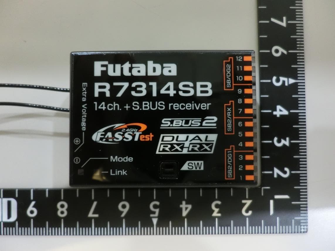
Click to zoom
Application Details
- Equipment Class
- DTS - Digital Transmission System
- Date of Grant
- Jul 31, 2023
- Application Purpose
- Original Equipment
- Date of Application
- Jul 30, 2023
- Equipment Note
- RECEIVER
- Frequency Range
- 2405.37600000 - 2472.96000000
- Company
- Futaba Corporation
- Country
- Japan
Documents & Files
Document Text
Text extracted from the exhibit documents filed with the FCC. Open a document above to read the original.
Users Manual
R7214SB Thank you for purchasing a Futaba R7214SB FASSTest-2.4GHz compatible receiver. The R7214SB receiver features bi-directional communication with a FASSTest Futaba transmitter using the S.BUS2 port. Using the S.BUS2 port an impressive array of telemetry sensors may be utilized. It also includes both standard PWM output ports (1-14ch) and S.BUS output ports. The R7214SB can also be switched to the Dual Rx Link System. This system can ensure safety by mounting two FASSTest receivers on one aircraft. 1M23N36204 ● Applicable systems: Futaba FASSTest-2.4GHz system transmitter ◆FASSTest-2.4GHz Bidirectional Communication System ◆Dual Rx Link System Equipment ◆S.BUS2 / S.BUS Port and 14 Channels for Conventional System Receiver *Be sure that when using ESCs regulated output the capacity of the ESC must meet your usage condition. *Never use dry batteries for the power sup- ply of the R7214SB as they may cause difficulties. R7214SB Specifications FASSTest-2.4 GHz system(18 ch/12 ch mode) S.BUS2 and S.BUS port and 14 channels for conventional system receiver • Dual antenna diversity • Size: 1.46 x 1.98 x 0.63 in. (37.0 x 50.2 x 15.9 mm) • Weight: 0.73 oz. (20.8 g) • Power requirement: 3.7 V to 7.4 V(Voltage range: 3.5 V to 8.4 V) • Battery F/S Voltage: It sets up with a transmitter • Extra Voltage port: 0 ~ 70 V DC + - S.BUS2 port (SB2/RX) (SB2/DG1) Port can be changed (Refer to separate table) When all ports are used. Servo for conventional system Mode LED Link LED Antenna Mode switch Extra Voltage Port (It is not used for a link.) It connects with the battery for power, etc. External voltage input cable of an option is used. The voltage of the battery can be displayed with a transmitter. S.BUS Servo S.BUS Gyro HUB HUB HUB HUB HUB HUB Battery 3.7~7.4 V Switch Servo A battery is connectable also with which port. Temperature Sensor Voltage Sensor Current Sensor RPM Sensor Altitude Sensor Airspeed Sensor S.BUS2 Tool S.BUS port (SB/DG2) Channel 12 output Channel 1 output (Typical installation) Receiver Do not insert either a switch or battery in this manner. DANGER RED ⇒ ORANGE ⇒ GREEN ⇒ ORANGE slow blink Blinks ORANGE once Blinks ORANGE twice Blinks ORANGE Solid ORANGE FASSTest12CH(Telemetry OFF)mode : ON FASSTest12CH(Telemetry OFF)mode : OFF 4 Press switch Press SW once more to return to flashing orange once 3 5 Press and hold the SW 6 Release SW Release the switch here 7 Turn off the receiver power Blinking switches every 5 seconds as follows. 1 Turn on the receiver. [Transmitter is always OFF] 2 Press and hold the SW for 5 seconds or more. FASSTest12CH(Telemetry OFF)mode This mode is forcibly turning off telemetry transmission to prevent collision of telemetry signals from the receiver to the transmitter when using dual RX link mode in FASSTest12ch mode. After restarting, the LINK LED lights up. In FASSTest12CH Telemetry OFF Mode StatusLINK LED StartOrange Solid Percentage of Waste Paper pulp 80% Change to this Change to this mode when using mode when using FASSTest12CH in FASSTest12CH in dual RX link mode.dual RX link mode. Compliance Information Statement (for U.S.A.) This device, trade name Futaba Corporation, model number R7214SB, complies with part15 of the FCC Rules. Operation is subject to the following two conditions: (1) This device may not cause harmful interference, and (2) This device must accept any interference received, including interference that may cause undesired operation. CAUTION: To assure continued FCC compliance 1. Any changes or modifications not expressly approved by the grantee of this device could void the user's authority to operate the equipment. 2. This equipment complies with FCC radiation exposure limits set forth for an uncontrolled environment. This equipment should be installed and operated with minimum distance 20cm between the radiator & your body. The responsible party of this device compliance is: FUTABA Corporation of America 2681 Wall Triana Hwy Huntsville, AL 35824, U.S.A. Phone:1-256- 461-9399 FAX:1-256- 461-1059 E-mail: ser [email protected] In FASSTest12CH mode, after linking R7214SB in telemetry OFF mode, link the receiver you want telemetry to. (The transmitter will show the telemetry of the last linked transmitter.) 1 Install two receivers on the aircraft as shown in the connection example. 2 Link the two receivers using the dual receiver feature of the transmitter. For systems without dual receiver capability, link each receiver in turn. Transmitter in link mode Transmitter in link mode For FASSTest 18CH Select dual mode and link primary *Follow the link procedure for each receiver manual. For FASSTest 18CH Select dual mode and link secondary Turn on the main receiver and link Turn on the sub receiver and link ◆ About telemetry system When using the dual receiver function ・The telemetry function of the main receiver can be used ・Sub-receiver telemetry function is not available How to Dual Rx Link Telemetry for FASSTest12CH FUTABA CORPORATION Hobby Radio Control Business Center Sales & Marketing Department 1080 Yabutsuka, Chosei-mura, Chosei-gun, Chiba-ken, 299-4395, Japan TEL: +81-475-32-6051, FAX: +81-475-32-2915 ©FUTABA CORPORATION 2023, 6 (1) Telemetry OFF mode Telemetry Telemetry Telemetry OFF mode First Link First Link Telemetry display of second-linked receiver. Telemetry OFF first-Linked receiver. Display Display #1 Second Link #2 Second Link #2 #2 #1 #1 #2 #2 FASSTest receiver e.g. R7214SB R7214SB R7214SB Antenna installation for carbon fuselage You must leave 30mm at the tip of the antenna fully exposed. The exposed antenna should be secured so that it cannot move around or back inside of your aircraft. Be careful of connector insertion Don't connect an S.BUS servo / gyro to S.BUS2 connector. Link precaution Do not perform the linking procedure while the motor's main power is connected or the engine is operating as it may result in serious injury. When the linking is complete, please cycle the receiver power and ensure the receiver …
Text truncated - open the document above for the full version.
Users Manual
R7314SB Thank you for purchasing a Futaba R7314SB FASSTest-2.4GHz compatible receiver. The R7314SB receiver features bi-directional communication with a FASSTest Futaba transmitter using the S.BUS2 port. Using the S.BUS2 port an impressive array of telemetry sensors may be utilized. It also includes both standard PWM output ports (1-14ch) and S.BUS output ports. The R7314SB can also be switched to the Dual Rx Link System. This system can ensure safety by mounting two FASSTest receivers on one aircraft. 1M23N36206 ● Applicable systems: Futaba FASSTest-2.4GHz system transmitter ◆FASSTest-2.4GHz Bidirectional Communication System ◆Dual Rx Link System Equipment ◆S.BUS2 / S.BUS Port and 14 Channels for Conventional System Receiver *Be sure that when using ESCs regulated output the capacity of the ESC must meet your usage condition. *Never use dry batteries for the power sup- ply of the R7314SB as they may cause difficulties. R7314SB Specifications FASSTest-2.4 GHz system(18 ch/12 ch mode) S.BUS2 and S.BUS port and 14 channels for conventional system receiver • Dual antenna diversity • Size: 1.46 x 1.98 x 0.63 in. (37.0 x 50.2 x 15.9 mm) • Weight: 0.69 oz. (19.5 g) • Power requirement: 3.7 V to 7.4 V(Voltage range: 3.5 V to 8.4 V) • Battery F/S Voltage: It sets up with a transmitter • Extra Voltage port: 0 ~ 70 V DC + - S.BUS2 port (SB2/RX) (SB2/DG1) Port can be changed (Refer to separate table) When all ports are used. Servo for conventional system Mode LED Link LED Antenna Mode switch Extra Voltage Port (It is not used for a link.) It connects with the battery for power, etc. External voltage input cable of an option is used. The voltage of the battery can be displayed with a transmitter. S.BUS Servo S.BUS Gyro HUB HUB HUB HUB HUB HUB Battery 3.7~7.4 V Switch Servo A battery is connectable also with which port. Temperature Sensor Voltage Sensor Current Sensor RPM Sensor Altitude Sensor Airspeed Sensor S.BUS2 Tool S.BUS port (SB/DG2) Channel 12 output Channel 1 output (Typical installation) Receiver Do not insert either a switch or battery in this manner. DANGER After restarting, the LINK LED lights up. In FASSTest12CH Telemetry OFF Mode StatusLINK LED StartOrange Solid Percentage of Waste Paper pulp 80% Compliance Information Statement (for U.S.A.) This device, trade name Futaba Corporation, model number R7314SB, complies with part15 of the FCC Rules. Operation is subject to the following two conditions: (1) This device may not cause harmful interference, and (2) This device must accept any interference received, including interference that may cause undesired operation. CAUTION: To assure continued FCC compliance 1. Any changes or modifications not expressly approved by the grantee of this device could void the user's authority to operate the equipment. 2. This equipment complies with FCC radiation exposure limits set forth for an uncontrolled environment. This equipment should be installed and operated with minimum distance 20cm between the radiator & your body. The responsible party of this device compliance is: FUTABA Corporation of America 2681 Wall Triana Hwy Huntsville, AL 35824, U.S.A. Phone:1-256- 461-9399 FAX:1-256- 461-1059 E-mail: ser [email protected] In FASSTest12CH mode, after linking R7314SB in telemetry OFF mode, link the receiver you want telemetry to. (The transmitter will show the telemetry of the last linked transmitter.) 1 Install two receivers on the aircraft as shown in the connection example. 2 Link the two receivers using the dual receiver feature of the transmitter. For systems without dual receiver capability, link each receiver in turn. Transmitter in link mode Transmitter in link mode For FASSTest 18CH Select dual mode and link primary *Follow the link procedure for each receiver manual. For FASSTest 18CH Select dual mode and link secondary Turn on the main receiver and link Turn on the sub receiver and link ◆ About telemetry system When using the dual receiver function ・The telemetry function of the main receiver can be used ・Sub-receiver telemetry function is not available How to Dual Rx Link Telemetry for FASSTest12CH FUTABA CORPORATION Hobby Radio Control Business Center Sales & Marketing Department 1080 Yabutsuka, Chosei-mura, Chosei-gun, Chiba-ken, 299-4395, Japan TEL: +81-475-32-6051, FAX: +81-475-32-2915 ©FUTABA CORPORATION 2023, 6 (1) Telemetry OFF mode→ACT Telemetry Telemetry Telemetry OFF mode→ACT First Link First Link Telemetry display of second-linked receiver. Telemetry OFF first-Linked receiver. Display Display #1 Second Link #2 Second Link #2 #2 #1 #1 #2 #2 FASSTest receiver e.g. R7314SB R7314SB R7314SB Antenna installation for carbon fuselage You must leave 30mm at the tip of the antenna fully exposed. The exposed antenna should be secured so that it cannot move around or back inside of your aircraft. Be careful of connector insertion Don't connect an S.BUS servo / gyro to S.BUS2 connector. Link precaution Do not perform the linking procedure while the motor's main power is connected or the engine is operating as it may result in serious injury. When the linking is complete, please cycle the receiver power and ensure the receiver is properly linked to the transmitter. Power on the system in this order: Transmitter first, followed by the receiver. If the R7314SB receiver was previously linked to another transmitter, make sure that transmitter is not operating while linking the receiver to the new transmitter. Connector precaution Don't connect a connector, as shown in this figure. ■ It will short-circuit, if it connected in this way. A short circuit across the battery terminals may cause abnormal heating, fire and burns. Usage precaution • Analog servos cannot be used with the R7314SB in the FASSTest 12CH mode. • Don't connect to Extra Voltage before turning on a receiver. • Analog servos move slightly at startup in the FASSTest 18CH mode. WARNING Changes or modification not approved by the party responsible for compliance could void the user’s …
Text truncated - open the document above for the full version.
External Photos
Futaba Corporation RECEIVER Model : R7214SB Series EUT External Photos Model: R7214SB Figure 1 General Appearance Figure 2 General Appearance (Front View) ANT Futaba Corporation RECEIVER Model : R7214SB Series Figure 3 General Appearance (Back View) Figure 4 General Appearance (U.FL-LP-068N1T-21-(120)D Antenna) Futaba Corporation RECEIVER Model : R7214SB Series Model: R7314SB Figure 5 General Appearance Figure 6 General Appearance (Front View) ANT Futaba Corporation RECEIVER Model : R7214SB Series Figure 7 General Appearance (Back View) Figure 8 General Appearance (ANTB24-104A0 Antenna)
ID Label/Location Info
Futaba Corporation RECEIVER Model : R7214SB Series FCC ID/IC Label Location Label Placement Location FCC ID/IC Label Format FCC ID/IC Label Placement Location Futaba Corporation RECEIVER Model : R7214SB Series FCC ID/IC Label Location Label Placement Location FCC ID/IC Label Format FCC ID/IC Label Placement Location
Internal Photos
Futaba Corporation RECEIVER Model : R7214SB Series EUT Internal Photos Model: R7214SB Figure 9 Internal View (RF Board, Front View) Figure 10 Internal View (RF Board, Back View) RF Chip Futaba Corporation RECEIVER Model : R7214SB Series Model: R7314SB Figure 11 Internal View (RF Board, Front View) Figure 12 Internal View (RF Board, Back View) RF Chip
RF Exposure Info
Maximum Permissive Exposure FCC ID: AZPR7214SB-24G Product Name: RECEIVER Model No: R7214SB, R7314SB According to FCC CFR 47 §1.1310, the criteria listed in the following table shall be used to evaluate the environmental impact of human exposure to radio frequency (RF) radiation as specified in 1.1307(b). Table 1 Limits for Maximum Permissible Exposure Futaba Corporation declares that the product described above has been evaluated and found to comply with the RF exposure limits for humans, as specified based on ANSI/FCC recommendation. Mode Max Output Power (dBm) Tune-up factor Tune-up max power (dBm) 2.4GHz 13.79 1.0094 13.92 **The value presented in the MPE is the maximum tune-up power. 2. MPE Calculation Based on safety distance (r) 20cm, the antenna gain (G) is 1.622Numerical, and the highest power output (P) is 24.660mW, the power density (S) is 0.007957mW/cm 2. RF Exposure Calculations: S = (P * G) / (4* π * r 2 ) or r = (P * G) / (4 * π * S) Where : Based on safety distance (r)= 20 cm Highest Power Output (P)= 13.92 dBm = 24.660 mW Antenna Gain (G)= 2.10 dBi = 1.622 Numerical MPE (S) = (P*G) / (4*π*r 2 ) = = (24.660*1.622)/(4*π*20 2 )= 0.007957 mW/cm 2 Sincerely Yours, Mr. Johnny Hsueh Section Manager AUDIX Technology Corporation
Test Report
㼓㼍㼕㼚㻔㼐㻮㼕䠅 㻾㻣㻞㻝㻠㻿㻮㻌㼍㼚㼠㼑㼚㼚㼍㻌㼏㼔㼍㼞㼍㼏㼠㼑㼞㼕㼟㼠㼕㼏㻜㻙㻢㻚㻞㻢 㻝㻡㻙㻢㻚㻜㻡 㼙㼛㼚㼛㻌㼜㼛㼘㼑㻌㼠㼥㼜㼑㻟㻜㻙㻡㻚㻤㻢 㻠㻡㻙㻡㻚㻣㻣 㻲㼞㼑㼝㼡㼑㼚㼏㼥㻌㻌㻞㻠㻠㻞㻹㻴㼦㻢㻜㻙㻡㻚㻠㻢 㻣㻡㻙㻡㻚㻣㻝 㻥㻜㻙㻡㻚㻠㻢 㻝㻜㻡㻙㻡㻚㻤㻞 㻝㻞㻜㻙㻢㻚㻝㻢 㻝㻟㻡㻙㻡㻚㻥㻟 㻝㻡㻜㻙㻡㻚㻡㻢 㻝㻢㻡㻙㻡㻚㻟㻟 㻝㻤㻜㻙㻡㻚㻝㻢 㻝㻥㻡㻙㻡㻚㻡㻡 㻞㻝㻜㻙㻡㻚㻣㻢 㻞㻞㻡㻙㻡㻚㻠㻞 㻞㻠㻜㻙㻡㻚㻝㻢 㻞㻡㻡㻙㻡㻚㻟㻤 㻞㻣㻜㻙㻡㻚㻠㻢 㻞㻤㻡㻙㻡㻚㻢㻢 㻟㻜㻜㻙㻢㻚㻜㻢 㻟㻝㻡㻙㻢㻚㻜㻞 㻟㻟㻜㻙㻡㻚㻢㻢 㻟㻠㻡㻙㻡㻚㻤㻝 㻙㻟㻡㻚㻜㻜 㻙㻟㻜㻚㻜㻜 㻙㻞㻡㻚㻜㻜 㻙㻞㻜㻚㻜㻜 㻙㻝㻡㻚㻜㻜 㻙㻝㻜㻚㻜㻜 㻙㻡㻚㻜㻜 㻜㻚㻜㻜 㻡㻚㻜㻜 㻜 㻝㻡 㻟㻜 㻠㻡 㻢㻜 㻣㻡 㻥㻜 㻝㻜㻡 㻝㻞㻜 㻝㻟㻡 㻝㻡㻜 㻝㻢㻡 㻝㻤㻜 㻝㻥㻡 㻞㻝㻜 㻞㻞㻡 㻞㻠㻜 㻞㻡㻡 㻞㻣㻜 㻞㻤㻡 㻟㻜㻜 㻟㻝㻡 㻟㻟㻜 㻟㻠㻡
Test Report
ページ ページページ ページ内容 内容内容 内容 三省電機株式会社 三省電機株式会社三省電機株式会社 三省電機株式会社 技術部 技術部技術部 技術部 〒142-0063 東京都品川区荏原5-11-13 TEL 03-3784-5103 / FAX 03-5749-7270 HP http://www.sansei-e.co.jp/ 1 アンテナ特性データ ―2.4GHzラジコン用アンテナ― 管理番号No.19-031SD 検認 担当 承認 発行日:2019年4月5日 小幡 清藤 1...... 表紙(本紙) 2~4...... 測定内容、測定アンテナ、VSWR 、最大利得 5...... 測定座標軸 6~14...... 指向特性 15...... 使用測定器 Antenna No.:ANTB24-104A0 Antenna Type:SLEEVE ANTENNA 2 I. 測定内容 II. 試作アンテナ ・アンテナ: 試作 真鍮切削チューブ使用 アンテナ No.1 – No.3 ・測定周波数 : 2400 MHz 2450 MHz 2500 MHz ・測定項目:VSWR 最大利得 指向特性 ・測定日: 2019年 4月 4日 III. VSWR 240024502500 No11.71.31.6 No21.91.41.7 No31.91.41.7 周波数 (MHz) VSWR 管理番号No.19-031SD 3 III. VSWR 試作 No.1 試作 No.2 管理番号No.19-031SD 4 III. VSWR 試作 No.3 IV. 最大利得 管理番号No.19-031SD 240024502500 No.11.561.931.50 No.21.402.101.87 No.31.351.911.48 最大利得 [dBi] 周波数 (MHz) サンプル 5 V. 測定座標軸 +X +Y +Z +X +Y ◎測定方向図 ◎測定軸 X – Y 軸 +X +Z Z – X 軸 管理番号No.19-031SD 2400MHz/X-Y面 VI. 指向特性 2400MHz/Z-X面 +Z +X +Y -Y -X +X -X -Z ◆No.1 -45.0 -40.0 -35.0 -30.0 -25.0 -20.0 -15.0 -10.0 -5.0 0.0 5.0 [deg] 0 90 180 270 -45.0 -40.0 -35.0 -30.0 -25.0 -20.0 -15.0 -10.0 -5.0 0.0 5.0 [deg] 0 90 180 270 6 管理番号No.19-031SD +X +Y -Y -X 2450MHz/X-Y面 2450MHz/Z-X面 ◆No.1 +Z +X -X -Z VI. 指向特性 -45.0 -40.0 -35.0 -30.0 -25.0 -20.0 -15.0 -10.0 -5.0 0.0 5.0 [deg] 0 90 180 270 -45.0 -40.0 -35.0 -30.0 -25.0 -20.0 -15.0 -10.0 -5.0 0.0 5.0 [deg] 0 90 180 270 7 管理番号No.19-031SD +X +Y -Y -X 2500MHz/X-Y面 2500MHz/Z-X面 ◆No.1 +Z +X -X -Z VI. 指向特性 -45.0 -40.0 -35.0 -30.0 -25.0 -20.0 -15.0 -10.0 -5.0 0.0 5.0 [deg] 0 90 180 270 -45.0 -40.0 -35.0 -30.0 -25.0 -20.0 -15.0 -10.0 -5.0 0.0 5.0 [deg] 0 90 180 270 8 管理番号No.19-031SD 2400MHz/X-Y面 2400MHz/Z-X面 +X +Y -Y -X ◆No.2 +Z +X -X -Z VI. 指向特性 -45.0 -40.0 -35.0 -30.0 -25.0 -20.0 -15.0 -10.0 -5.0 0.0 5.0 [deg] 0 90 180 270 -45.0 -40.0 -35.0 -30.0 -25.0 -20.0 -15.0 -10.0 -5.0 0.0 5.0 [deg] 0 90 180 270 9 管理番号No.19-031SD 2450MHz/X-Y面 2450MHz/Z-X面 +X +Y -Y -X +Z +X -X -Z ◆No.2 VI. 指向特性 -45.0 -40.0 -35.0 -30.0 -25.0 -20.0 -15.0 -10.0 -5.0 0.0 5.0 [deg] 0 90 180 270 -45.0 -40.0 -35.0 -30.0 -25.0 -20.0 -15.0 -10.0 -5.0 0.0 5.0 [deg] 0 90 180 270 10 管理番号No.19-031SD 2500MHz/X-Y面 2500MHz/Z-X面 +X +Y -Y -X +Z +X -X -Z ◆No.2 VI. 指向特性 -45.0 -40.0 -35.0 -30.0 -25.0 -20.0 -15.0 -10.0 -5.0 0.0 5.0 [deg] 0 90 180 270 -45.0 -40.0 -35.0 -30.0 -25.0 -20.0 -15.0 -10.0 -5.0 0.0 5.0 [deg] 0 90 180 270 11 管理番号No.19-031SD 2400MHz/X-Y面 2400MHz/Z-X面 +X +Y -Y -X ◆No.3 +Z +X -X -Z VI. 指向特性 -45.0 -40.0 -35.0 -30.0 -25.0 -20.0 -15.0 -10.0 -5.0 0.0 5.0 [deg] 0 90 180 270 -45.0 -40.0 -35.0 -30.0 -25.0 -20.0 -15.0 -10.0 -5.0 0.0 5.0 [deg] 0 90 180 270 12 管理番号No.19-031SD 2450MHz/X-Y面 2450MHz/Z-X面 +X +Y -Y -X +Z +X -X -Z ◆No.3 VI. 指向特性 -45.0 -40.0 -35.0 -30.0 -25.0 -20.0 -15.0 -10.0 -5.0 0.0 5.0 [deg] 0 90 180 270 -45.0 -40.0 -35.0 -30.0 -25.0 -20.0 -15.0 -10.0 -5.0 0.0 5.0 [deg] 0 90 180 270 13 管理番号No.19-031SD 2500MHz/X-Y面 2500MHz/Z-X面 +X +Y -Y -X +Z +X -X -Z ◆No.3 VI. 指向特性 -45.0 -40.0 -35.0 -30.0 -25.0 -20.0 -15.0 -10.0 -5.0 0.0 5.0 [deg] 0 90 180 270 -45.0 -40.0 -35.0 -30.0 -25.0 -20.0 -15.0 -10.0 -5.0 0.0 5.0 [deg] 0 90 180 270 14 管理番号No.19-031SD
Test Report
Page 1 of 29 Audix Technology Corp. Tel: +886 2 26099301 No. 491, Zhongfu Rd., Linkou Dist., Fax: +886 2 26099303 New Taipei City244,Taiwan File Number: C1M2305048 Report Number: EM-F230300 This test report may be reproduced in full only. The document may only be updated by Audix Technology Corp. personnel. Any changes will be noted in the Document History section of the report. FCC 15.247 & RSS-247 2.4GHz Test Report for FUTABA Corporation 1080 YabutsukaChosei-son Chosei-gun, Chiba-ken, 299-4395 Japan. Product Name : RECEIVER Model Name : (1)R7214SB (2)R7314SB Brand Futaba FCC ID : AZPR7214SB-24G IC : 2914D-R7214SB Prepared by: : AUDIX Technology Corporation, EMC Department The test report is based on a single evaluation of one sample of the above-mentioned products. It does not imply an assessment of the whole production and does not permit the use of the test lab logo. Page 2 of 29 Audix Technology Corp. Tel: +886 2 26099301 No. 491, Zhongfu Rd., Linkou Dist., Fax: +886 2 26099303 New Taipei City244,Taiwan File Number: C1M2305048 Report Number: EM-F230300 This test report may be reproduced in full only. The document may only be updated by Audix Technology Corp. personnel. Any changes will be noted in the Document History section of the report. TABLE OF CONTENTS Description Page TEST REPORT ................................................................................................................................... 4 1. REVISION RECORD OF TEST REPORT ............................................................................ 5 2. SUMMARY OF TEST RESULTS ........................................................................................... 6 3. GENERAL INFORMATION ................................................................................................... 7 3.1. Description of Application .............................................................................................................. 7 3.2. Description of EUT ......................................................................................................................... 8 3.3. Reference Test Guidance ................................................................................................................. 9 3.4. Antenna Information ....................................................................................................................... 9 3.5. EUT Specifications Assessed in Current Report ............................................................................. 9 3.6. Descriptions of Key Components .................................................................................................. 10 3.7. Test Configuration ......................................................................................................................... 10 3.8. Output Power Setting .................................................................................................................... 12 3.9. Tested Supporting System List ...................................................................................................... 12 3.10. Setup Configuration ....................................................................................................................... 13 3.11. Operating Condition of EUT ......................................................................................................... 13 3.12. Description of Test Facility ........................................................................................................... 14 3.13. Measurement Uncertainty ............................................................................................................. 15 4. MEASUREMENT EQUIPMENTLIST ................................................................................. 17 4.1. Radiated Emission Measurement .................................................................................................. 17 4.2. RF Conducted Measurement ......................................................................................................... 17 5. CONDUCTED EMISSION ..................................................................................................... 18 6. RADIATED EMISSION ......................................................................................................... 19 6.1. Block Diagram of Test Setup ........................................................................................................ 19 6.2. Radiated Emission Limits .............................................................................................................. 20 6.3. Test Procedure ............................................................................................................................... 21 6.4. Measurement Result Explanation .................................................................................................. 22 6.5. Test Results ................................................................................................................................... 22 7. DTS/OCCUPIED BANDWIDTH ........................................................................................... 23 7.1. Block Diagram of Test Setup ........................................................................................................ 23 7.2. Specification Limits ....................................................................................................................... 23 7.3. Test Procedure ............................................................................................................................... 23 7.4. Test Results ................................................................................................................................... 23 8. MAXIMUM PEAK OUTPUT POWER ................................................................................ 24 8.1. Block Diagram of Test Setup ........................................................................................…
Text truncated - open the document above for the full version.
Test Report
APPENDIX A-Page 1 of 35 Audix Technology Corp. Tel: +886 2 26099301 No. 491, Zhongfu Rd., Linkou Dist., Fax: +886 2 26099303 New Taipei City244, Taiwan File Number: C1M2305048 Report Number: EM-F230300 This test report may be reproduced in full only. The document may only be updated by Audix Technology Corp. personnel. Any changes will be noted in the Document History section of the report. TABLE OF CONTENTS A.1 RADIATED EMISSION .......................................................................................................... 2 A.1.1 Emissions within Restricted Frequency Bands ............................................................................. 2 A.1.2 Emissions outside the frequency band: ....................................................................................... 21 A.1.3 Emissions in Non-restricted Frequency Bands: .......................................................................... 24 A.2 DTS/OCCUPIED BANDWIDTH .......................................................................................... 25 A.2.1 DTS/Occupied Bandwidth Result ............................................................................................... 25 A.2.2 Measurement Plots ..................................................................................................................... 26 A.3 MAXIMUM PEAK OUTPUT POWER ............................................................................... 28 A.3.1 Peak Output Power ..................................................................................................................... 28 A.3.2 Measurement Plots ..................................................................................................................... 29 A.4 EMISSION LIMITATIONS .................................................................................................. 30 A.5 POWER SPECTRAL DENSITY .......................................................................................... 34 A.5.1 Power Spectral Density Result ................................................................................................... 34 A.5.2 Measurement Plots ..................................................................................................................... 35 APPENDIX A-Page 2 of 35 Audix Technology Corp. Tel: +886 2 26099301 No. 491, Zhongfu Rd., Linkou Dist., Fax: +886 2 26099303 New Taipei City244, Taiwan File Number: C1M2305048 Report Number: EM-F230300 This test report may be reproduced in full only. The document may only be updated by Audix Technology Corp. personnel. Any changes will be noted in the Document History section of the report. A.1 RADIATED EMISSION Test Date 2023/05/25~29 Temp./Hum. 22~24°C/40~64% Test Voltage DC 6V (Via Battery) Tested By Harry Huang A.1.1 Emissions within Restricted Frequency Bands A.2.1.1 Frequency 9kHz~30MHz The emissions (9kHz~30MHz) not reported for there is no emission be found. A.2.1.2 Frequency Below 1GHz Test Model: R7214SB, ANT A Mode FASSTest Frequency TX 2472.960MHz Antenna at Horizontal Polarization Emission Frequency Antenna Factor Cable Loss Preamp Gain Read Level Emission Level Limits Margin Detector (MHz) (dB/m) (dB) (dB) (dBV) (dBV/m) (dBV/m) (dB) 33.880 22.50 1.28 26.51 31.16 28.43 40.00 11.57 Peak 101.780 16.96 2.32 26.30 34.21 27.20 43.50 16.30 Peak 167.740 16.01 3.06 25.94 40.48 33.60 43.50 9.90 Peak 198.780 15.36 3.39 25.81 41.14 34.07 43.50 9.43 Peak 300.630 19.32 4.37 25.67 35.24 33.26 46.00 12.74 Peak 979.630 26.89 9.16 26.81 32.63 41.86 54.00 12.14 Peak Antenna at Vertical Polarization Emission Frequency Antenna Factor Cable Loss Preamp Gain Read Level Emission Level Limits Margin Detector (MHz) (dB/m) (dB) (dB) (dBV) (dBV/m) (dBV/m) (dB) 41.640 18.38 1.42 26.50 37.92 31.22 40.00 8.78 Peak 112.450 17.61 2.45 26.23 33.89 27.72 43.50 15.78 Peak 141.550 17.42 2.78 26.06 34.58 28.72 43.50 14.78 Peak 278.320 18.97 4.16 25.69 32.51 29.94 46.00 16.06 Peak 654.680 24.58 7.07 27.40 32.90 37.14 46.00 8.86 Peak 984.480 26.95 9.19 26.80 32.93 42.27 54.00 11.73 Peak APPENDIX A-Page 3 of 35 Audix Technology Corp. Tel: +886 2 26099301 No. 491, Zhongfu Rd., Linkou Dist., Fax: +886 2 26099303 New Taipei City244, Taiwan File Number: C1M2305048 Report Number: EM-F230300 This test report may be reproduced in full only. The document may only be updated by Audix Technology Corp. personnel. Any changes will be noted in the Document History section of the report. Test Model: R7214SB, ANT B Mode FASSTest Frequency TX 2472.960MHz Antenna at Horizontal Polarization Emission Frequency Antenna Factor Cable Loss Preamp Gain Read Level Emission Level Limits Margin Detector (MHz) (dB/m) (dB) (dB) (dBV) (dBV/m) (dBV/m) (dB) 35.820 21.78 1.32 26.51 31.56 28.15 40.00 11.85 Peak 101.780 16.96 2.32 26.30 34.23 27.22 43.50 16.28 Peak 198.780 15.36 3.39 25.81 40.18 33.11 43.50 10.39 Peak 233.700 17.53 3.73 25.75 36.64 32.15 46.00 13.85 Peak 515.970 23.64 6.46 27.20 33.31 36.21 46.00 9.79 Peak 977.690 26.88 9.15 26.82 32.63 41.84 54.00 12.16 Peak Antenna at Vertical Polarization Emission Frequency Antenna Factor Cable Loss Preamp Gain Read Level Emission Level Limits Margin Detector (MHz) (dB/m) (dB) (dB) (dBV) (dBV/m) (dBV/m) (dB) 40.670 18.93 1.40 26.50 37.49 31.32 40.00 8.68 Peak 105.660 17.21 2.37 26.27 34.17 27.47 43.50 16.03 Peak 141.550 17.42 2.78 26.06 34.72 28.86 43.50 14.64 Peak 199.750 15.35 3.40 25.81 36.47 29.41 43.50 14.09 Peak 858.380 25.72 8.41 27.14 33.64 40.64 46.00 5.36 Peak 974.780 26.86 9.14 26.83 32.84 42.01 54.00 11.99 Peak Test Model: R7314SB, ANT A Mode FASSTest Frequency TX 2472.960MHz Antenna at Horizontal Polarization Emission Frequency Antenna Factor Cable Loss Preamp Gain Read Level Emission Level Limits Margin Detector (MHz) (dB/m) (dB) (dB) (dBV) (dBV/m) (dBV/m) (dB) 35.820 21.78 1.32 26.51 31.14 27.73 40.00 12.27 Peak 101.780 16.96 2.32 26.30 34.00 26.99 43.50 16.51 Peak 193.930 15.40 3.33 25.83 38.00 30.90 43.50 12.60 Peak 277.350…
Text truncated - open the document above for the full version.
Contact Information
Applicant
Toshikazu Hama(Manager)
Technical Contact
Test Firm
Audix Technology CorporationAllen Wang
Technical Specifications
| # | Rule Parts | Frequency Range | Power Output |
|---|---|---|---|
| 1 | 15C | 2.41 GHz - 2.47 GHz | 23.93 mW |
Other Applications from Futaba Corporation

AZP-FEX11T
Jan 22, 20262.4GHz band Module
Equipment Class
DSS - Part 15 Spread Spectrum Transmitter
AZPCGY770R-24G
Aug 19, 2024Radio Control
Equipment Class
DTS - Digital Transmission SystemAZPTM18
Jan 21, 2024Radio Control
Equipment Class
DSS - Part 15 Spread Spectrum TransmitterAZPR9001SB
Jan 17, 2024Radio Control
Equipment Class
DSS - Part 15 Spread Spectrum Transmitter
AZPR7201SB-24G
Jan 14, 2024Receiver
Equipment Class
DTS - Digital Transmission System