AZPT14SG-24GRadio Control
Futaba Corporation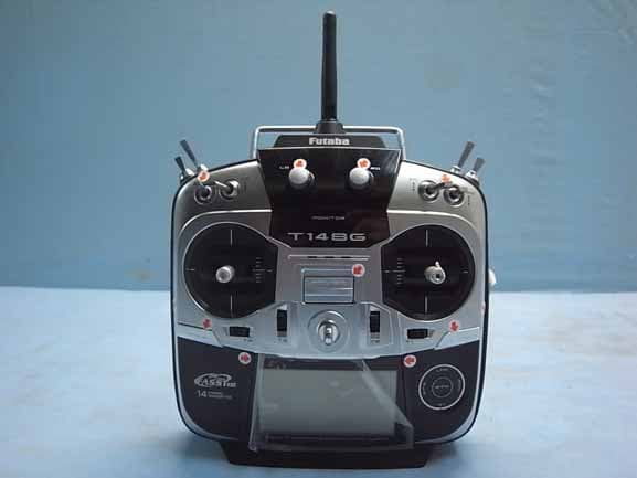
Click to zoom
Application Details
- Equipment Class
- DTS - Digital Transmission System
- Date of Grant
- Feb 05, 2013
- Application Purpose
- Original Equipment
- Date of Application
- Feb 05, 2013
- Equipment Note
- Radio Control
- Frequency Range
- 2405.37600000 - 2477.05600000
- Company
- Futaba Corporation
- Country
- Japan
Documents & Files
Document Text
Text extracted from the exhibit documents filed with the FCC. Open a document above to read the original.
Users Manual
14 CHANNEL COMPUTER SYSTEM TM TM Technical updates and additional programming examples available at: http://www.futaba-rc.com/faq Entire Contents © 2012 2 <Table of Contents> INTRODUCTION...............................................4 ●Support and Service .........................................4 ●Application, Export, and Modification ...........5 ●Definitions of Symbols ......................................6 ●Safety Precautions (do not operate without reading) .............................................................6 BEFORE USE ...................................................10 ●Features of 14SG ............................................10 ●Contents and technical specifications ...........11 ●Accessories .......................................................12 ●Transmitter controls .......................................13 Cautions on handling antenna ......................14 LED monitor ...................................................14 Switch (SA-SH) ...............................................15 Digital trim (T1-T4) .......................................15 Volume (LD, RD) ............................................15 Slide Lever (LS, RS) .......................................15 HOME/EXIT, U.MENU/MON. Button ........15 Touch sensor ...................................................16 Stick adjustment .............................................17 SD card ............................................................19 Connector/Plug ...............................................21 Installation and removal of the battery ........22 ●Receiver nomenclature ...................................24 ●Receiver's antenna installation ......................26 ●Safety precautions when installing servos ...27 ●S.BUS/S.BUS2 Installation ............................28 ●S.BUS Wiring example ...................................29 ●S.BUS2 System ................................................30 ●S.BUS/S.BUS2 Devicesetting .........................31 ●Telemetry System ............................................32 BASIC OPERATION .......................................33 ●Battery Charging ............................................33 How to charge the NiMH Battery .................33 ●How to turn ON/OFF the transmitter ..........34 When turning on ............................................34 When turning off ............................................34 Low battery alarm and auto shut-down ......34 Warning display at power on ........................34 ●Registration of the user's name .....................34 ●Home screen ....................................................35 User Menu .......................................................36 ●Link procedure (T14SG/R7008SB) ...............37 ●Range testing your R/C system......................39 RACEIVER AND SERVO INSTALLATION .40 ●Receiver and servos connection .....................40 ●Servo connection by model type ....................41 MODEL BASIC SETTING PROCEDURE ...44 ●Airplane/glider basic setting procedure ........44 ●Helicopter basic setting procedure ................46 FUNCTIONS OF SYSTEM MENU ................50 Trainer .............................................................51 Display .............................................................54 User Name .......................................................55 Sound ...............................................................56 H/W Setting .....................................................57 Start SEL. .......................................................59 Auto Lock .......................................................62 Information ....................................................63 SBUS Servo ....................................................64 FUNCTIONS OF LINKAGE MENU .............67 (Common Functions) Linkage Menu functions table ......................67 Servo Monitor .................................................68 Model Select ....................................................69 Model Type......................................................71 TABLE OF CONTENTS 3 <Table of Contents> System .............................................................73 Function ..........................................................76 Sub-Trim .........................................................78 Servo Reverse .................................................79 Fail Safe ...........................................................80 End Point ........................................................81 Servo Speed ....................................................82 Throttle Cut (Air/Heli only) ..........................83 Idle Down (Air only) ......................................84 Swash Ring (Heli only) ..................................85 Swash (Heli only, except H-1) ........................86 T1-T4 Setting ..................................................89 Warning ...........................................................90 Telemetry.........................................................91 Telemetry:Rx-batt ..........................................92 Telemetry:Ext-volt .........................................93 Telemetry:temp...............................................94 Telemetry:rpm ................................................95 Telemetry:altitude ..........................................96 Telemetry:vario ..............................................97 Telemetry:battery ...........................................98 Telemetry:distance .........................................99 Telemetry:speed ............................................101 Sensor ............................................................102 Sensor:reload ................................................103 Sensor:register ..............................................103 Sensor:relocate .............................................104 Sensor:set slot ...............................................104 Data Reset ..................................…
Text truncated - open the document above for the full version.
Users Manual
31 <Before Use> S.BUS/S.BUS2 device setting S.BUS/S.BUS2 servos or a telemetry sensor can be connected directly to the T14SG. Channel setting and other data can be entered for the S.BUS/S.BUS2 servos or sensors. 3-way hub or Y-harnesses (S.BUS/S.BUS2 Servo) S.BUS/S.BUS2 device (Telemetry sensor) Receivers Battery T14SG 1. Connect the S.BUS device and battery you want to set with a 3-way hub or Y-harnesses as shown in the figure. 2. Turn on the transmitter power. 3. Call the setup screen. Servo: System Menu → S.BUS Servo Sensor: Linkage Menu → Sensor 4. Perform setting in accordance with each screen. 5. This sets the channel and other data for each S.BUS servo, or telemetry device to be used with the S.BUS device or receiver. 32 <Before Use> Telemetry System The R7008SB receiver features bi-directional communication with a FASSTest Futaba transmitter using the S.BUS2 port. Using the S.BUS2 port an impressive array of telemetry sensors may be utilized. It also includes both standard PWM output ports and S.BUS output ports. * Telemetry is available only in the FASSTest 14CH mode. (12CH mode displays only Receiver battery voltage and Extra battery voltage.) * The telemetry function requires the corresponding receiver (R7008SB). * The T14SG will enter and keep the ID number of the R7008SB that it is linked to. S.BUS2 Connector Temperature Sensor Switch T14SG Terminal box HUB HUB HUB RPM Sensor Altitude Sensor Voltage Sensor GPS Sensor ***Sensor ***Sensor ***Sensor Your aircrafts data can be checked in the transmitter by connecting various telemetry sensors to the S.BUS2 connector of the receiver. Servos are classified by channel, but sensors are classified by “slot” . Since the initial slot No. of the T14SG is preset at each sensor, the sensors can be used as is by connecting them. There are 1 31 slots. 33 <Basic Operation> BASIC OPERATION How to charge the NiMH battery HT5F1800B for the transmitter Danger The NiMH battery HT5F1800B is only for your T14SG. Do not use this battery for other equipment. Be sure to use the attached special charger to charge the battery. *If you take the NiMH battery HT5F1800B out of the transmitter, you can use the optional quick charger CR-2000 corresponding to NiMH battery. [Method of charging battery] *Connect to AC outlet specified. ● Special charger Receiver Batt. Charging display To T14SG charge connector Transmitter Batt. Charging display 1. Connect the special charger to the wall socket (AC outlet). 2. Connect the connectors to the T14SG charging jack. *Confirm that the charging indicator, LED lamp, is on. *Turn off the transmitter while charging the battery. 3. Remove the battery after 15 hours. *Battery charging will not automatically stop. Remove the battery and transmitter from the charger and remove the charger from the wall socket. *It is recommended to reactivate the battery by cycling several times if the battery has not been used for a long period. *In the case of NiMH/NiCd batteries, you may find poor performance of the battery if you have used the battery only for a short period or if you repeat charging while the battery is not fully discharged. It is suggested to discharge the battery to the recommended level after use. It is also recommended to charge the battery just before use. Battery Charging Before charging batteries, read the "Cautions for handling battery and battery charger" in the section "NiMH/NiCd Battery Safety and Handling Instructions". 34 <Basic Operation> How to turn transmitter power ON/OFF When turning on the power, the T14SG transmitter will begin emmiting RF automatically after it confirms the surrounding RF conditions. The T14SG transmitter also offers the ability to auto shut-down. When turning on the power of the transmitter 1. Turn on the power switch of the transmitter. *The message "CHECK RF CONDITION" is displayed for a moment. At the same time the left LED monitor blinks. 2. Then, you will see the home screen and the transmitter begins to emit radio waves. *The left and right LED monitors will change to solid red. How to stop the transmitter 1. Turn off the power switch of the transmitter. *The transmitter shuts down at once. Low battery alarm and auto shut-down When the battery voltage reaches 5.2V, an audible alarm will sound. Land your aircraft immediately. When the battery voltage reaches 3.9V, the transmitter will be turned off automatically. *If you do not operate the transmitter (or move a stick, knob, switch or digital trim) for 30 minutes, the message "PLEASE TURN OFF POWER SWITCH" is displayed and an audible alarm will sound. Warning display at power ON (Airplane/ Helicopter) When the throttle stick during Power On is at the high side (or over 1/3 stick) a warning will be displayed. *below 1/3 stick, the warning display goes off. Registration of the user's name If so desired, the T14SG transmitter can indicate the owner's name. User's name setup screen 1. Turn on the power of the transmitter. *The home screen appears. 2. Lightly touch the SYS button twice rapidly and the System menu appears. 3. Select [USER NAME] in the System menu and touch the RTN button. *The user name set up screen appears. Input Box *Current user name is displayed. Changing the user name 1. Change the user name as described below: [Moving cursor in input box] Select [←] or [→], and touch the RTN button. [Deleting a character] When [DELETE] is selected and the RTN button is touched, the character immediately after the cursor is deleted. [Adding a character] When a character is selected from the character list and the RTN button is touched, that character is added at the position immediately after the cursor. *A name of up to 10 characters long can be entered as the user name. (A space is also counted as one character.) 2. At the end of input, select [ENTER] and tuoch the RTN button. (To terminate input and return to the original state, select [CANCEL] and touch the RTN button.) THR Stick Slow 35 <Basic Operation> Up/Down timer (ST1, …
Text truncated - open the document above for the full version.
Cover Letter(s)
Authority to Act as Agent Date: Jan. 30, 2013 American Certification Body, Inc. 6731 Whittier Avenue Suite C110 McLean, VA 22101 To Whom It May Concern: ____AUDIX Technology Corporation _____ is authorized to act on our behalf, until otherwise notified, for applications to American Certification Body, Inc. (ACB). We certify that we are not subject to denial of federal benefits, that includes FCC benefits, pursuant to Section 5301 of the Anti-Drug Abuse Act of 1988, 21 U.S.C. 862. Further, no party, as defined in 47 CFR 1.2002 (b), to the application is subject to denial of federal benefits, that includes FCC benefits. Thank you, Agency Agreement Expiration Date: _____Jan. 30, 2014_____ By: __________________________ __ Kazunori Fujita _ _____ (Signature) (Print name) Title: ___PM_____________________ On behalf of: ____ Futaba Corporation __ ____ (Company Name) Telephone: __ +81-475-32-6019 _ ____
Cover Letter(s)
Request for Confidentiality Date: Jan. 30, 2013 Federal Communications Commission Authorization and Evaluation Division Subject: Confidentiality Request regarding Application for certification of FCC ID: AZPT14SG-24G Gentlemen: Pursuant to Section 0.457 and 0.459 of the Commission’s Rules, we hereby request confidential treatment of information accompanying this application as outlined below: Functional Block Diagram Operational Description (theory of operation) Schematic Diagram The above materials contain trade secrets and proprietary information not customarily released to the public. The public disclosure of these materials may be harmful to the applicant and provide unjustified benefits to its competitors. The Applicant understands that pursuant to Section 0.457 of the Rules, disclosure of this application and all accompanying documentation will not be made before the date of the Grant for this application. Sincerely, _______________________________________ Kazunori Fujita Raido Control Equipment Group Manager Futaba Corporation
External Photos
FUTABA Corporation Radio Control FCC ID. : AZPT14SG-24G EUT External Photos Figure 1 General Appearance (Front View) Figure 2 General Appearance (Side View) Antenna FUTABA Corporation Radio Control FCC ID. : AZPT14SG-24G Figure 3 General Appearance (Back View) Figure 4 General Appearance (Side View)
ID Label/Location Info
FUTABA Corporation Radio Control FCC ID. : AZPT14SG-24G FCC ID Label Location z Label Placement Location z FCC Label Format FCC Label Placement Location
Internal Photos
FUTABA Corporation Radio Control FCC ID. : AZPT14SG-24G EUT Internal Photos Figure 5 Internal View (Removed Side Cover) Figure 6 Internal View (Battery, Front View) FUTABA Corporation Radio Control FCC ID. : AZPT14SG-24G Figure 7 Internal View (Battery, Front View) Figure 8 Internal View (Removed Cover) RF Module Antenna FUTABA Corporation Radio Control FCC ID. : AZPT14SG-24G Figure 9 Internal View Figure 10 Internal View (RF Antenna View) FUTABA Corporation Radio Control FCC ID. : AZPT14SG-24G Figure 11 Internal View (TB47B-A Board, Front View) Figure 12 Internal View (TB72A-10 Board, Front View) FUTABA Corporation Radio Control FCC ID. : AZPT14SG-24G Figure 13 Internal View (TB72A-10 Board, Back View) Figure 14 Internal View (Control Board) FUTABA Corporation Radio Control FCC ID. : AZPT14SG-24G Figure 15 Internal View (TB72A-7) Figure 16 Internal View (Control Board) FUTABA Corporation Radio Control FCC ID. : AZPT14SG-24G Figure 17 Internal View Figure 18 Internal View (TB72A-9 Board, Back View) FUTABA Corporation Radio Control FCC ID. : AZPT14SG-24G Figure 19 Internal View (TB72A-9 Board, Front View) Figure 20 Internal View (LCD Panel, Front View) FUTABA Corporation Radio Control FCC ID. : AZPT14SG-24G Figure 21 Internal View (LCD Panel, Back View) Figure 22 Internal View (RF Module Board, Front View) FUTABA Corporation Radio Control FCC ID. : AZPT14SG-24G Figure 23 Internal View (RF Module Board/Removed shielded Cover, Front View) Figure 24 Internal View (RF Module Board, Back View) FUTABA Corporation Radio Control FCC ID. : AZPT14SG-24G Figure 25 Internal View (TB72A-1 Board, Front View) Figure 26 Internal View (TB72A-1 Board, Back View)
RF Exposure Info
Maximum Permissive Exposure FCC ID: AZPT14SG-24G Product Name: Radio Control Model No: T14SG Futaba Corporation declares that the product described above has been evaluated and found to comply with the RF exposure limits for humans, as specified based on ANSI/FCC recommendation. Based on safety distance 20cm, the antenna gain of 2.4GHz is 1.5 dBi, and the power output is 48.194mW in FASST which is the highest power of 3 modes, the power density is 0.0135 mW/cm^2. RF Exposure Calculations: S = (P * G) / (4* * r^2) or r = (P * G) / (4 * * S) Where S = Power Density in mW/cm^2 P = 16.83dBm =48.194mW G = 1.5 dBi = 1.41 Numerical r = 20cm S = 48.194*1.41 / 4** 20^2 = 0.0135mW/cm^2 Sincerely Yours, ____________________________________ Mr. Ben Cheng Manager AUDIX Technology Corporation
Test Report
FCC ID. AZPT14SG-24G Page 1 of 70 AUDIX Technology Corporation Report No. EM-F1020091 APPLICATION FOR CERTIFICATION On Behalf of FUTABA Corporation Radio Control Model No.T14SG FCC IDAZPT14SG-24G Brand: Futaba Prepared for : FUTABA Corporation 1080 Yabutsuka Chosei-son Chosei-gun Chiba, 299-4395 Japan. Prepared by : AUDIX Technology Corporation EMC Department No. 53-11, Dingfu, Linkou Dist., New Taipei City 244, Taiwan, R.O.C. Tel : (02) 2609-9301, 2609-2133 Fax: (02) 2609-9303 File Number C1M1210216 Report Number EM-F1020091 Date of Test Jan. 23 ~ 28, 2013 Date of Report Jan. 29, 2013 FCC ID. AZPT14SG-24G Page 2 of 70 AUDIX Technology Corporation Report No. EM-F1020091 TABLE OF CONTENTS Description Page TEST REPORT CERTIFICATION .......................................................................................................4 1. GENERAL INFORMATION .......................................................................................................4 1.1. Description of Device (EUT).................................................................................................................. 4 1.2. Description of Test Facility .................................................................................................................... 5 1.3. Measurement Uncertainty....................................................................................................................... 5 2. CONDUCTED EMISSION MEASUREMET.............................................................................6 3. RADIATED EMISSION MEASUREMENT ..............................................................................7 3.1. Test Equipment ....................................................................................................................................... 7 3.2. Test Setup ............................................................................................................................................... 7 3.3. Radiated Emission Limits (§15.209) ...................................................................................................... 9 3.4. Operating Condition of EUT .................................................................................................................. 9 3.5. Test Procedure ........................................................................................................................................ 9 3.6. Radiated Emission Measurement Results............................................................................................. 10 4. 6dB BANDWIDTH MEASUREMENT .....................................................................................48 4.1. Test Equipment ..................................................................................................................................... 48 4.2. Block Diagram of Test Setup................................................................................................................ 48 4.3. Specification Limits (§15.247(a)(2)) .................................................................................................... 48 4.4. Operating Condition of EUT ................................................................................................................ 48 4.5. Test Procedure ...................................................................................................................................... 48 4.6. Test Results........................................................................................................................................... 49 5. MAXIMUM PEAK OUTPUT POWER MEASUREMENT ...................................................53 5.1. Test Equipment ..................................................................................................................................... 53 5.2. Block Diagram of Test Setup................................................................................................................ 53 5.3. Specification Limits (§15.247(b)-(3))................................................................................................... 53 5.4. Operating Condition of EUT ................................................................................................................ 53 5.5. Test Procedure ...................................................................................................................................... 53 5.6. Test Results........................................................................................................................................... 54 6. EMISSION LIMITATIONS MEASUREMENT ......................................................................55 7. BAND EDGES MEASUREMENT.............................................................................................56 7.1. Test Equipment ..................................................................................................................................... 56 7.2. Block Diagram of Test Setup................................................................................................................ 56 7.3. Specification Limits (§15.247(c))......................................................................................................... 56 7.4. Operating Condition of EUT ................................................................................................................ 56 7.5. Test Procedure ...................................................................................................................................... 56 7.6. Test Results........................................................................................................................................... 56 8. POWER SPECTRAL DENSITY MEASUREMENT ..............................................................61 8.1. Test Equipment ...........................................................................................................................…
Text truncated - open the document above for the full version.
Test Setup Photos
FCC ID. AZPT14SG-24G Page 67 of 70 AUDIX Technology Corporation Report No. EM-F1020091 10. PHOTOGRAPHS 10.1. Photos of Radiated Measurement at Semi-Anechoic Chamber 10.1.1.Frequency Range 30MHz~1GHz EUT on Stand EUT on Side FCC ID. AZPT14SG-24G Page 68 of 70 AUDIX Technology Corporation Report No. EM-F1020091 EUT on Lying 10.1.2.Frequency Range Above 1GHz EUT on Stand FCC ID. AZPT14SG-24G Page 69 of 70 AUDIX Technology Corporation Report No. EM-F1020091 EUT on Side EUT on Lying FCC ID. AZPT14SG-24G Page 70 of 70 AUDIX Technology Corporation Report No. EM-F1020091 10.2. Photo of RF Conducted Measurement 10.3. Photo of Section Maximum Peak Output Power Measurement
Contact Information
Applicant
Toshikazu Hama(Manager)
Technical Contact
Audix TechnologyBen Cheng
[email protected]88626099301
No. 53-11 Tin-fu, Tsun Lin Kou Hsiang · Taipei County · Taiwan
Test Firm
Audix Technology CorporationLeon Liu
Technical Specifications
| # | Rule Parts | Frequency Range | Power Output |
|---|---|---|---|
| 2 | 15C | 2.41 GHz - 2.48 GHz | 48.19 mW |
Other Applications from Futaba Corporation

AZP-FEX11T
Jan 22, 20262.4GHz band Module
Equipment Class
DSS - Part 15 Spread Spectrum Transmitter
AZPCGY770R-24G
Aug 19, 2024Radio Control
Equipment Class
DTS - Digital Transmission SystemAZPTM18
Jan 21, 2024Radio Control
Equipment Class
DSS - Part 15 Spread Spectrum TransmitterAZPR9001SB
Jan 17, 2024Radio Control
Equipment Class
DSS - Part 15 Spread Spectrum Transmitter
AZPR7201SB-24G
Jan 14, 2024Receiver
Equipment Class
DTS - Digital Transmission System