AZPT3GR-24GRadio Control Transmitter
Futaba Corporation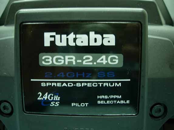
Click to zoom
Application Details
- Equipment Class
- DTS - Digital Transmission System
- Date of Grant
- Sep 06, 2007
- Application Purpose
- Original Equipment
- Date of Application
- Sep 06, 2007
- Equipment Note
- Radio Control Transmitter
- Frequency Range
- 2405.37600000 - 2479.10400000
- Company
- Futaba Corporation
- Country
- Japan
Documents & Files
Document Text
Text extracted from the exhibit documents filed with the FCC. Open a document above to read the original.
Users Manual
3GR-2.4G 3-channel, FASST Radio control system for Car 1M23N18005 Thank you for purchasing a Futaba 3GR-2.4GHz system. Before using your 3GR-2.4GHz system, read this manual carefully in order to use your R/C set safely. After reading this manual, store it in a safe place. Application, Export, and Modification 1. This product may be used for models only. It is not intended for use in any application other than the control of models for hobby and recreational purposes. 2. Exportation precautions: (a) When this product is exported from the country of manufacture, its use is to be approved by the laws govern- ing the country of destination for devices that emit radio frequencies. If this product is then re-exported to other countries, it may be subject to restrictions on such export. Prior approval of the appropriate goverment authori- ties may be required. If you have purchased this product from an exporter outside your country, and not the authorized Futaba distributor in your country, please contact the seller immediately to determine if such export regulations have been met. (b) Use of this product with other than models may be restricted by Export and Trade Control Regulations, and an application for export approval must be submitted. 3. Modification, adjustment, and replacement of parts: Futaba is not responsible for unauthorized modification, adjustment, and replacement of parts on this product. Any such changes may void the warranty. Compliance Information Statement (for U.S.A.) This device, trade name Futaba Corporation of America, model number R603FF, complies with part 15 of the FCC Rules. Operation is subject to the following two conditions: (1) This device may not cause harmful interference, and (2) This device must accept any interference received, including interference that may cause undesired operation. The responsible party of this device compliance is: Futaba Service Center 3002 N Apollo Drive Suite 1, Champaign, IL 61822 U.S.A. TEL (217)398-8970 or E-mail: [email protected] (Support) TEL (217)398-0007 or E-mail: [email protected] (Service) Battery Recycling (for U.S.A.) The RBRC TM SEAL on the (easily removable) nickel-cadmium battery contained in Futaba products indicates that Futaba Corporation of America is voluntarily participating in an industry program to collect and recycle these batteries at the end of their useful lives, when taken out of service within the United States. The RBRC TM program provides a convenient alternative to placing used nickel-cadmium batteries into the trash or mu- nicipal waste system, which is illegal in some areas. You may contact your local recycling center for information on where to return the spent battery. Please call 1-800-8-BATTERY for information on Ni-Cd battery recycling in your area. Futaba Cor- poration of America's involvement in this program is part of its commitment to protecting our environ- ment and conserving natural resources. RBRC TM is a trademark of the Rechargeable Battery Recycling Corporation. Warning: This product contains a chemical known to cause cancer and birth defects (or other reproductive harm). •No part of this manual may be reproduced in any form without prior permission. •The contents of this manual are subject to change without prior notice. •This manual has been carefully written. Please write to Futaba if you feel that any corrections or clarifications should be made. •Futaba is not responsible for the use of this product. 4 For Your Safety As Well As That Of Others ........... 6 Explanation of Symbols ................................................................................ 6 2.4GHz System Precautions ......................................................................... 6 Operation Precautions .................................................................................. 7 NiCd Battery Handling Precautions ............................................................. 9 Storage and Disposal Precautions ............................................................ 10 Other Precautions ....................................................................................... 11 Table Of Contents Before Using ........................................................... 12 Features ........................................................................................................ 12 Set Contents ................................................................................................ 14 Nomenclature (Transmitter/Receiver/Servo) ............................................ 15 Installation .............................................................. 21 Receiver and Servo Connections .............................................................. 21 Installation Safety Precautions .................................................................. 21 Initial Set-Up ........................................................... 23 How to link the transmitter and the receiver ............................................. 23 Preparations (Transmitter) ......................................................................... 24 Functions ................................................................ 30 End Point Adjuster ...................................................................................... 30 Steering Speed ............................................................................................ 33 Steering EXP / Throttle EXP ....................................................................... 34 A.B.S. Function ............................................................................................ 36 Throttle Acceleration ................................................................................... 38 Brake Mixing ................................................................................................ 40 Programmable Mixing ................................................................................. 41 Fail Safe/Battery Fail Safe (HRS …
Text truncated - open the document above for the full version.
Cover Letter(s)
1 Chris Harvey From: Audix Tech \(敦吉檢測\) Tina Huang [[email protected]] Sent: Thursday, September 06, 2007 1:57 AM To: [email protected] Cc: 劉李煌 副總; 鄭又銘 課長; shelene; cherry Subject: Fw: Futaba Corporation, FCC ID: AZPT3GR-24G, Assessment NO.: AN07T7161, Notice#1 Dear Chris: About AN07T7161 question, Bleow is our answers: 1. The Theory of Operation revised and uploaded to the CCS website. 2. About Form 731. Could you help me to revise Equipment into Class DTS, thanks!! Because I don't know how to revise it on CCS websiet. Could you tell me how to revise it, thanks!! 3. The 12VDC (with dry cell battery) is correct. You can see page 58 of manual. 4. There are 2 RF connectors. 5. The power of the EUT is 49.317mW and the Declaration of Compliance revised and uploaded to the CCS website Thank you!! Best regards, Tina Huang [email protected] >> ----- Original Message ----- >> From: <[email protected]> >> To: <[email protected]> >> Cc: <[email protected]> >> Sent: Wednesday, September 05, 2007 3:52 AM >> Subject: Futaba Corporation, FCC ID: AZPT3GR-24G, Assessment NO.: >> AN07T7161, Notice#1 >> >> >>> Dear Leon Liu, >>> >>> You are listed as the Technical Contact for the above referenced TCB >>> application. The following item(s) need(s) to be resolved before >>> the review can be continued: >>> >>> 1. The Theory of Operation indicates that the upper frequency is >>> 2477.056 MHz, where the Form 731 and test report indicate 2479.104 MHz. >>> Please update the Theory of Operation. >>> >>> 2. The application Form 731 was submitted for Equipment Class DXX, >>> where this Direct Sequence Spread Spectrum device fits into >>> Equipment Class DTS. Please confirm that it is acceptable for me to >>> make the change on the application Form. >>> >>> 3. The test report indicates that this device operates on 12VDC, >>> where the manual indicates 6VDC operation. >>> >>> 4. The internal photos seem to show 2 RF connectors. Are there 2 RF >>> connectors? >>> 2 >>> Please note that the MPE calculation exhibit shows a power of 69.502 >>> mW, where the test report and Form 731 show a power of 49.317mW. >>> You do not need to correct this exhibit since is actually calculates >>> a worse condition than the maximum power of the EUT. >>> >>> The items indicated above must be submitted before processing can >>> continue on the above referenced application. Failure to provide the >>> requested information within 30 days of the original e-mail date may >>> result in application dismissal and forfeiture of the filing fee. >>> Also, please note that partial responses increase processing time >>> and should not be submitted. Any questions about the content of this >>> correspondence should be directed to the e-mail address listed below >>> the name of the sender. >>> >>> Best regards, >>> >>> Chris Harvey >>> [email protected] >>> >>> >>> >> >> > >
Cover Letter(s)
1 Chris Harvey From: Audix Tech(敦吉檢測)Tina Huang [[email protected]] Sent: Friday, September 07, 2007 4:30 AM To: [email protected] Cc: 鄭又銘 課長; 劉李煌 副總; cherry; shelene Subject: Fw: Futaba Corporation, FCC ID: AZPT3GR-24G, Assessment NO.: AN07T7161, Notice#2 Attachments: FUTABA FCC ID AZPT3GR-24G.doc FUTABA FCC ID AZPT3GR-24G.doc .. Dear Chris: Sorry, we make a mistake!! The device has only one RF connector. About RF Connector question, please see bleow our customer respose mail. Thank you!! Tina ----- Original Message ----- From: <[email protected]> To: "Audix Tech ("敦吉檢測") Tina Huang" <[email protected]> Cc: "鄭又銘 課長" <[email protected]>; "cherry" <[email protected]>; "shelene" <[email protected]> Sent: Friday, September 07, 2007 3:49 PM Subject: Re: About T3GR-2.4G FCC ID Question > > Dear Ms.Tina > > This model has only one RF port. > The true RF port is RF port1 . > > RF port2 is not RF port. > This is a part called variable resister which is used adjusting RF output > level. > > with best regards > > Susumu Sakuma > Engineering Unit 1 > Radio Control Equipment Group > Electronic System Division > Futaba corporation > > > |---------+----------------------------> > | | Audix Tech(敦吉檢| > | | 測)Tina Huang | > | | <tina_huang@audix| > | | tech.com> | > | | | > | | 2007/09/07 16:35 | 2 > | | | > |---------+----------------------------> > > >-------------------------------------------------------------------------------------- -----------------------------------------| > | > | > | 宛先: "Futaba Mr. Susuma Sakum" <[email protected]> > | > | cc: "cherry" <[email protected]>, 鄭又銘 課長 > <[email protected]>, "shelene" <[email protected]> | > | 件名: About T3GR-2.4G FCC ID Question > | > > >-------------------------------------------------------------------------------------- -----------------------------------------| > > > > > > > Dear Sakuma-san: > > We received the mail from TCB this morning. > Accroding to the list below question(NO.2 question), > This question need your help. > > [You indicate that there are 2 RF connectors. Please clarify this > situation for me. Are both RF connectors used in this device? Do both RF > paths transmit? If yes, do they transmit at the same time?] > > Please teach us, thanks! > > > Best regards, > > Tina > > > > > ----- Original Message ----- >> From: <[email protected]> >> To: <[email protected]> >> Cc: <[email protected]> >> Sent: Thursday, September 06, 2007 8:47 PM >> Subject: Futaba Corporation, FCC ID: AZPT3GR-24G, Assessment NO.: > AN07T7161, >> Notice#2 >> >> >>> Tina, thank you for your response. As for updating the application > form, >>> I think I must make the change, which is why I asked if you would allow >>> mew to make the change. >>> >>> You indicate that there are 2 RF connectors. Please clarify this >>> situation for me. Are both RF connectors used in this device? Do both > RF >>> paths transmit? If yes, do they transmit at the same time? >>> >>> I am sorry about not seeing that the 6VDC is for the receiver operation. > 3 >>> I now see that the 12VDC is for the transmitter operation. >>> >>> The items indicated above must be submitted before processing can > continue >>> on the above referenced application. Failure to provide the requested >>> information within 30 days of the original e-mail date may result in >>> application dismissal and forfeiture of the filing fee. Also, please > note >>> that partial responses increase processing time and should not be >>> submitted. Any questions about the content of this correspondence should > >>> be directed to the e-mail address listed below the name of the sender. >>> >>> Best regards, >>> >>> Chris Harvey >>> >>> >>> >> >> > > >
Cover Letter(s)
FUTABA FCC ID: AZPT3GR-24G Control Connector of RF Module Station & function description RF Module set RF Port 1 RF Port 2 RF Port2 RF Port1
External Photos
Futaba Corporation Radio Control FCC ID. : AZPT3GR-24G EUT External Photos Figure 1 General Appearance (Front View) Figure 2 General Appearance (Front & Side View) Futaba Corporation Radio Control FCC ID. : AZPT3GR-24G Figure 3 General Appearance (Back & Side View) Figure 4 General Appearance (Bottom View) Futaba Corporation Radio Control FCC ID. : AZPT3GR-24G Figure 5 General Appearance (Product Label)
ID Label/Location Info
Futaba Corporation Radio Control FCC ID. : AZPT3GR-24G FCC ID Label Location z Label Placement Location z FCC Label Format FCC Label Placement Location
Internal Photos
Futaba Corporation Radio Control FCC ID. : AZPT3GR-24G EUT Internal Photos Figure 6 Internal View (Removed Battery Cover) Figure 7 Internal View (Removed Cover) Futaba Corporation Radio Control FCC ID. : AZPT3GR-24G Figure 8 Internal View (Antenna View) Figure 9 Internal View (Main Board, Front View) Futaba Corporation Radio Control FCC ID. : AZPT3GR-24G Figure 10 Internal View (Main Board, Back View) Figure 11 Internal View (Control Board and RF Board) Futaba Corporation Radio Control FCC ID. : AZPT3GR-24G Figure 12 Internal View (Control Board, Front View) Figure 13 Internal View (Control Board, Back View) Futaba Corporation Radio Control FCC ID. : AZPT3GR-24G Figure 14 Internal View (RF Board, Front View) Figure 15 Internal View (RF Board, Back View) Futaba Corporation Radio Control FCC ID. : AZPT3GR-24G Figure 16 Internal View (Control Board, Back View) Figure 17 Internal View (Control Board, Front View)
Test Report
FCC ID. AZPT3GR-24G Page 1 of 61 Audix Technology Corporation Report No. EM-F960416 APPLICATION FOR CERTIFICATION On Behalf of Futaba Corporation Radio Control Model No.T3GR-2.4G FCC IDAZPT3GR-24G Brand : Futaba Prepared for : Futaba Corporation 1080 Yabutsuka Chosei-son Chosei-gun Chiba, 299-4395 Japan. Prepared by : Audix Technology Corporation EMC Department No. 53-11, Tin-Fu Tsun, Lin-Kou, Taipei, Taiwan Tel : (02) 2609-9301, 2609-2133 Fax: (02) 2609-9303 File Number EM961161 Report Number EM-F960416 Date of Test Aug. 21, 2007 Date of Report Aug. 27, 2007 FCC ID. AZPT3GR-24G Page 2 of 61 Audix Technology Corporation Report No. EM-F960416 TABLE OF CONTENTS Description Page TEST REPORT CERTIFICATION .......................................................................................................4 1. GENERAL INFORMATION .........................................................................................................5 1.1. Description of Device (EUT).................................................................................................................. 5 1.2. Tested Supporting System Details .......................................................................................................... 6 1.3. Description of Test Facility .................................................................................................................... 7 1.4. Measurement Uncertainty....................................................................................................................... 8 2. CONDUCTED EMISSION MEASUREMET...............................................................................9 3. RADIATED EMISSION MEASUREMENT ..............................................................................10 3.1. Test Equipment ..................................................................................................................................... 10 3.2. Test Setup ............................................................................................................................................. 10 3.3. Radiated Emission Limits (§15.209) .................................................................................................... 12 3.4. Operating Condition of EUT ................................................................................................................ 12 3.5. Test Procedure ...................................................................................................................................... 12 3.6. Test Results........................................................................................................................................... 13 4. 6dB BANDWIDTH MEASUREMENT .......................................................................................37 4.1. Test Equipment ..................................................................................................................................... 37 4.2. Block Diagram of Test Setup................................................................................................................ 37 4.3. Specification Limits (§15.247(a)(2)) .................................................................................................... 37 4.4. Operating Condition of EUT ................................................................................................................ 37 4.5. Test Procedure ...................................................................................................................................... 37 4.6. Test Results........................................................................................................................................... 38 5. MAXIMUM PEAK OUTPUT POWER MEASUREMENT .....................................................41 5.1. Test Equipment ..................................................................................................................................... 41 5.2. Block Diagram of Test Setup................................................................................................................ 41 5.3. Specification Limits (§15.247(b)-(3))................................................................................................... 41 5.4. Operating Condition of EUT ................................................................................................................ 41 5.5. Test Procedure ...................................................................................................................................... 41 5.6. Test Results........................................................................................................................................... 42 6. EMISSION LIMITATIONS MEASUREMENT ........................................................................43 6.1. Test Equipment ..................................................................................................................................... 43 6.2. Block Diagram of Test Setup................................................................................................................ 43 6.3. Specification Limits (§15.247(c))......................................................................................................... 43 6.4. Operating Condition of EUT ................................................................................................................ 43 6.5. Test Procedure ...................................................................................................................................... 43 6.6. Test Results........................................................................................................................................... 44 7. BAND EDGES MEASUREMENT...............................................................................................47 7.1. Test Equipment ...............................................................................…
Text truncated - open the document above for the full version.
Test Setup Photos
FCC ID. AZPT3GR-24G Page 53 of 61 Audix Technology Corporation Report No. EM-F960416 10. PHOTOGRAPHS 10.1. Photos of Radiated Measurement at Semi-Anechoic Chamber 10.1.1. Frequency Range 30MHz~1GHz Position: Stand FRONT VIEW OF RADIATED MEASUREMENT BACK VIEW OF RADIATED MEASUREMENT FCC ID. AZPT3GR-24G Page 54 of 61 Audix Technology Corporation Report No. EM-F960416 Position: Side FRONT VIEW OF RADIATED MEASUREMENT BACK VIEW OF RADIATED MEASUREMENT FCC ID. AZPT3GR-24G Page 55 of 61 Audix Technology Corporation Report No. EM-F960416 Position: Lie FRONT VIEW OF RADIATED MEASUREMENT BACK VIEW OF RADIATED MEASUREMENT FCC ID. AZPT3GR-24G Page 56 of 61 Audix Technology Corporation Report No. EM-F960416 10.1.2. Frequency Above 1GHz Position: Stand FRONT VIEW OF RADIATED MEASUREMENT BACK VIEW OF RADIATED MEASUREMENT FCC ID. AZPT3GR-24G Page 57 of 61 Audix Technology Corporation Report No. EM-F960416 Position: Side FRONT VIEW OF RADIATED MEASUREMENT BACK VIEW OF RADIATED MEASUREMENT FCC ID. AZPT3GR-24G Page 58 of 61 Audix Technology Corporation Report No. EM-F960416 Position: Lie FRONT VIEW OF RADIATED MEASUREMENT BACK VIEW OF RADIATED MEASUREMENT FCC ID. AZPT3GR-24G Page 59 of 61 Audix Technology Corporation Report No. EM-F960416 10.2. Photo of 6dB Bandwidth Measurement 10.3. Photo of Maximum Peak Output Measurement FCC ID. AZPT3GR-24G Page 60 of 61 Audix Technology Corporation Report No. EM-F960416 10.4. Photo of Emission Limitations Measurement 10.5. Photo of Band Edges Measurement FCC ID. AZPT3GR-24G Page 61 of 61 Audix Technology Corporation Report No. EM-F960416 10.6. Photo of Power Spectral Density Measurement
Contact Information
Applicant
Toshikazu Hama(Manager)
Test Firm
Audix Technology CorporationLeon Liu
Technical Specifications
| # | Rule Parts | Frequency Range | Power Output |
|---|---|---|---|
| 1 | 15C | 2.41 GHz - 2.48 GHz | 49.32 mW |
Other Applications from Futaba Corporation

AZP-FEX11T
Jan 22, 20262.4GHz band Module
Equipment Class
DSS - Part 15 Spread Spectrum Transmitter
AZPCGY770R-24G
Aug 19, 2024Radio Control
Equipment Class
DTS - Digital Transmission SystemAZPTM18
Jan 21, 2024Radio Control
Equipment Class
DSS - Part 15 Spread Spectrum TransmitterAZPR9001SB
Jan 17, 2024Radio Control
Equipment Class
DSS - Part 15 Spread Spectrum Transmitter
AZPR7201SB-24G
Jan 14, 2024Receiver
Equipment Class
DTS - Digital Transmission System