AZPT6EXA-726 Channel Aircraft Radio Control
Futaba Corporation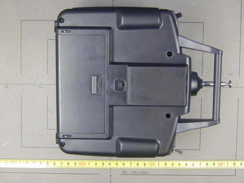
Click to zoom
Application Details
- Equipment Class
- TNB - Licensed Non-Broadcast Station Transmitter
- Date of Grant
- Mar 18, 2003
- Application Purpose
- Original Equipment
- Date of Application
- Mar 18, 2003
- Equipment Note
- 6 Channel Aircraft Radio Control
- Frequency Range
- 72.01000000 - 72.99000000
- Company
- Futaba Corporation
- Country
- Japan
Documents & Files
Document Text
Text extracted from the exhibit documents filed with the FCC. Open a document above to read the original.
Users Manual
IINNSSTTRRUUCCTTIIOONN MMAANNUUAALL ffoorr FFuuttaabbaa 66EEXXAA 6-channel, FM radio control system for aircraft Futaba Corporation Technical updates available at: http://www.futaba-rc.com FUTZ9032 for FUTK55** V1.0Entire Contents © Copyright 2003 66 EEXXAA INTRODUCTION Thank you for purchasing the Futaba ® 6EXA digital proportional R/C aircraft system. If this is your first “computer” radio, rest assured that it is designed to make initial setup and field-tuning of your airplane easier and more accurate than would be if using a “non-computer” radio. Although this is a beginneror sportsystem with the requirements of those flyers in mind, in order to make the best use of your Futaba 6EXA and to operate it safely, you mmust ccarefully rread aall oof tthe iinstructions . Suggestion: If, while reading the instructions, you are unclear of some of the procedures or functions and become “stuck,” continue to read on anyway. Often, the function or procedure will be explained again later in a different way providing another perspective from which to understand it. Another suggestion is to connect the battery, switch and servos to the receiver and actually operate the radio on your workbench as you make programming changes. Then, you’ll be able to see the effects of your programming inputs. 2 Introduction ...................................................................................2 Service ............................................................................................2 Contents aand sspecifications .......................................................3 Glossary .........................................................................................3 Introduction tto tthe 66EXA ssystem ...............................................4 Transmitter ccontrols aand ddescriptions ......................................4 Radio iinstallation .........................................................................5 Receiver aand sservo cconnections ................................................7 Charging tthe NNi-CCd bbatteries ......................................................7 LCD aand PProgramming ccontrols .................................................8 Programming tthe TT6EXA rradio ..................................................9 Model select/Data reset ....................................................10 Servo reversing ....................................................................10 Dual rates .............................................................................10 Exponentials.........................................................................11 End Point Adjustments.......................................................11 Trims......................................................................................12 Programmable Mixer..........................................................12 Pre programmed “wing” mixing .......................................13 Flow chart.............................................................................16 Other TT6EXA ffunctions ..............................................................17 Trainer switch.......................................................................17 Flap control lever .................................................................17 Adjustable-length control sticks .......................................18 Changing the stick mode...................................................18 Flying ssafety gguidelines ............................................................18 Flight ppreparation ......................................................................19 Frequency CChart .........................................................................20 Futaba AAccessories ....................................................................20 Model DData RRecording SSheets .................................................21 TABLE OOF CCONTENTS This product is to be used for sport and recreational flying of radio-control models only. Futaba is not responsible for the results of use of this product by the customer or for any alteration of this product, including modification or incorporation into other devices by third parties. Modification will void any warranty and is done at the owner’s risk. Protect the environment by disposing of rechargeable batteries responsibly. Throwing rechargeable batteries into the trash or municipal waste system is illegal in some areas. Call 1-800-8-BATTERY for information about Ni-Cd battery recycling in your area. SERVICE If any difficulties are encountered while setting up or operating your system, please consult the instruction manual first. For further assistance you may also refer to your hobby dealer, or contact the Futaba Service Center at the web site, fax number or telephone number below: www.futaba-rrc.com Fax: ((217) 3398-77721 Telephone ((8:00 aam tto 55:00 ppm CCentral ttime MMonday tthrough FFriday): ((217) 3398-88970, eextension 22 If unable to resolve the problem, pack the system in its original container with a note enclosed and a thorough , accurate description of the problem(s). Include the following in your note: •Symptoms.•Any unusual mounting conditions. •An inventory of items enclosed.•The items that require repair. •Your name, address, and telephone number.•Include the warranty card if warranty service is requested. Send your system to the authorized Futaba R/C Service Center at the address below: Futaba SService CCenter 3002 NN AApollo DDrive SSuite 11 Champaign, IIL 661822 GLOSSARY It will be helpful to understand the following terms before reading the rest of the manual. The terms are not in alphabetical order, but are in a logical order that prepares the reader for understanding the next term. Reversing ((servo rreversing) – A function that allows the user to determine the direction of response of each servo. If, after hooking up the servos, a control on the model responds in the wrong direction, the user may cha…
Text truncated - open the document above for the full version.
Users Manual
INTRODUCTION TTO TTHE 66EXA SSYSTEM IMPORTANT!: Always turn on the transmitter first, then the receiver. When turning off the system, always turn off the receiver first. The object is never to have the receiver on by itself. Otherwise, the servos or control surfaces could be damaged, or in the case of electric-powered models, the motor may unexpectedly turn on causing severe injury. IMPORTANT!: Never collapse the transmitter antenna by pushing down from the top. If one of the segments becomes momentarily stuck you may damage the antenna. Instead, collapse the antenna from the bottom, drawing in one segment at a time. Transmitter The T6EXA FM 6-channel transmitter may be used with any Futaba, narrow band, FM receiver. The liquid-crystal display (LCD) on the face of the compact, ergonomically-designed case is easy to read and allows rapid data input. The system also holds independent memories for six different models. The new, adjustable-length control sticks provide an improved feel. External switches operate dual rates (D/R), landing gear, and trainer cord or “buddy-box” capabilities. Programming features include servo reversing and E.P.A on all channels, dual rates, exponentials and programmable mixing. Additionally, any one of four, factory-set, preprogrammed “wing-type” mixers including flaperon, V-tail, elevon or flaperon + V-tail mixing may be selected. Transmitter ccontrols The diagram and explanations briefly describe the functions of the Futaba T6EXA transmitter. Full instructions on how to operate the controls are provided beginning on page 9. NOTE: The diagram shows a Mode 2 system as supplied. (More on flight modes on page 18). DESCRIPTIONS: Aileron aand EElevator ddual rrate sswitch Use this switch to “flip” between two aileron and elevator control throw settings. The throws can be set up however you prefer, but generally, when the switch is “up” the throws are greater (“high rate”) and when the switch is “down” the throws are less (“low rate”). This switch also flips between exponential rates (if used). Flap ccontrol ddial/Channel 66 - This dial operates the servo connected to channel 6 in the receiver—if your model has flaps this is the control used to operate them. Neck sstrap hhook - Mounting point for optional neck strap. Aileron/elevator ccontrol sstick - Operates the servos connected to channel 1 (aileron) and channel 2 (elevator) in the receiver. Trim llevers ((all) - Used to shift the neutral or centerposition of each servo as labeled in the diagram. NOTE: The throttle trim lever is intended for fine tuning the throttle servo when the engine is at idle. Throttle trim does not affect the throttle servo when the throttle control stick is all the way up (so idle r.p.m. can be adjusted without affecting throttle settings through the rest of the stick movement). 4 Aileron & Elevator dual rate switch Antenna Retractable landing gear switch / CH.5 Flap control dial / CH.6 Carrying handle Liquid-crystal display screen (LCD) Throttle/rudder control stick MODE key SELECT key Trainer /throttle cut switch Neck strap hook Charging jack On-off switch Rudder trim lever Throttle trim lever DATA INPUT lever Aileron trim lever Elevator trim lever Aileron/elevator control stick Charging jjack – Port for charging the transmitter batteries with the included battery charger. On-ooff sswitch DATA IINPUT llever – Used to change the values of the various functions displayed on the LCD screen. Liquid-ccrystal ddisplay sscreen (LCD) – Displays programming modes and values entered. MODE kkey - Used to scroll through and display the seven different functions. SELECT kkey - Used to display the values for the current function. Throttle/rudder ccontrol sstick - Operates the servos connected to channel 3 (throttle) and channel 4 (rudder) in the receiver. Trainer/throttle-ccut sswitch - Operates both the trainer and throttle-cut functions. To operate as a trainer switch the transmitter must be connected to another transmitter via. a trainer cord (available separately). To use the throttle-cut function, lower the throttle stick all the way, then rapidly depress the switch twice to fully close the carburetor and shut off the engine. Retractable llanding ggear sswitch/Channel 55 – Switch operates the servo connected to channel 5 in the receiver—if your model has retractable landing gear this is the control used to extend and retract the gear. Antenna – Radiates signals to the receiver. Never fly a model without fully extending the antenna or you may create interference to other modelers and decrease operational signal range of the transmitter. The antenna may be removed and replaced with another in case it is inadvertently broken. RADIO IINSTALLATION Follow these guidelines to properly mount the servos, receiver and battery. • Make certain the alignment ttab on the battery, switch and servo connectors is oriented correctly and “keys” into the corresponding notch in the receiver or connectors before plugging them in. When unplugging connectors, never pull on the wires. Always pull on the plastic connector instead. • If any servo wires are not long enough to reach the receiver, servo extension wires (available separately) may be used. • Always mount the servos with the supplied rubber ggrommets . Do not over tighten the screws. No part of the servo casing should contact the mounting rails, servo tray or any other part of the airplane structure. Otherwise, vibration will be transmitted to the servo causing premature wear and/or servo failure. • Note the small numbers (1, 2, 3, 4) molded into each arm on the Futaba 4-arm servo arms. The numbers indicate how many degrees each arm is “off” from 90 degrees to correct for minute manufacturing deviations from servo to servo. • To center the servos, connect them to the receiver and turn on the transmitter and receiver. Center the trims on the transmitter, then find the arm that will be perpendicular to the pushrod when placed on the servo. 5 • After the servos ar…
Text truncated - open the document above for the full version.
Users Manual
MODEL —— MModel SSelect/Data RReset Model sselect ffunction Access the Model Select function in the programming mode (by pressing the MODE and SELECT keys simultaneously and holding them down for one second). The number for the current, active model will be blinking. To activate a different model memory press the DATA INPUT lever until the desired model number appears. Now the model has been selected. All programming inputs from this point forward will affect only the model number on the screen (until another model number is selected). Data rreset ffunction All the data for any model memory can be reset to the original, factory defaults. Often this function is done to get a “fresh start” and clear the memory before inputting new model settings. To rreset ddata: 1. Access the Model Select function in the programming mode (by pressing the MODE and SELECT keys simultaneously and holding them down for one second). Use the DATA INPUT lever to select the model memory you wish to reset. 2. Once the desired model number is displayed on the screen, press the SELECT key. A “CL” will appear on the screen. 3. Press the DATA INPUT up or down for two seconds to clear and reset the memory. Now the data for this model has been reset to the original, factory defaults. CAUTION: Resetting the current model memory will permanently erase ALL programming information for that model. The data cannot be recovered (unless you recorded it on a Model Data Recording Sheet in the back of this manual). Do not reset the model unless certain you want to flush-out that memory and start from scratch. When actually setting up a model you should have the model in front of you with the power on so you can actually see the effects of your programming inputs and measure the control throws. REVERSE —— SServo RReversing The servo reversing function is used to change the direction that a servo responds to a control input from the transmitter (stick, dial or switch). After using the reversing function, check all the controls on the model to be ccertain they are operating in the correct direction and that you did not inadvertently reverse a servo other than the one intended. Reversing the wrong servo (and not checking the response of the controls before each flight) may be the most common cause of a crash! To rreverse aa sservo: 1. Enter the programming mode and use the MODE key to access the REVERSE function. 2. Use the SELECT key to select the channel you wish to reverse. The active channel number will be displayed in the upper, right corner of the screen. 3. Push the DATA INPUT lever down to reverse the servo (REV), or push the lever up to make the servo operate normally (NOR). The arrow will indicate the condition of the servo (normal or reversed). In the diagram channel 1 (aileron) is “normal” (not reversed). 4. Use the SELECT key to display other channels to be reversed. D/R —— DDual RRates/Exponential SSettings The aileron and elevator dual rates on the 6EXA are simultaneously activated by the dual rate switch. The amount of travel decrease for each control may be set between 0% and 100% of the values set for the end points (explained in End Point Adjustment on page 11). Note: When performing initial model setup, the E.P.A.s should be set prior tto setting the dual rates. When setting the E.P.A.s for the first time on a new model, the dual rates should be set to 100%. Note: It is possible to set a dual rate value to zero, thus causing no response from that channel. If the dual rates are inadvertently set to zero, a crash could result. 10 Dual RRate SSettings To sset tthe ddual rrates: 1. Enter the programming mode. Access the D/R screen with the MODE key. 2. Select the channel to be adjusted (1-aileron, 2-elevator) by pressing the SELECT key until the desired channel number appears on the screen. Note: If a + or a – appears next to the number, you have pressed the SELECT key too many times and displayed the values for the exponentials (explained later). Press the SELECT key to return to the dual rate values. 3. Place the dual rate switch in the desired position for the value you wish to change. (Generally, pilots prefer to have the switch in the “up” position for the high rate, and in the “down” position for the low rate.) 4. Change the dual rate value using the DATA INPUT lever until the desired control throw is achieved. If you wish to change the control throw when the switch is in the other position as well, flip the switch, then use the DATA INPUT lever to change the throw. 5. Repeat the procedure for the other dual rate (channel 2-elevator). Exponential SSettings The “exponentials” are in the same function as the dual rates. (Pressing the MODE key will take you to the next function which is End Point Adjustments). The same as dual rates, “expos” can be set for both switch positions. Negative exponential (-) decreases initial servo movement. Positive exponential (+) increases initial servo movement. The exponential “curve” may be set anywhere between -100% and +100%. To sset tthe eexponentials: 1. Enter the programming mode, then select the channel (1-aileron, 2-elevator) you wish to set by pressing the SELECT key. The active channel number will be displayed on the screen with a + or a - next to the number (initially, the value will read ± 0) 2. Position the dual rate switch where desired for the value you wish to change. 3. Enter the amount of exponential with the DATA INPUT lever. (As stated above, an exponential value with a “-” in front of it makes the initial servo movement less, or “softer.”) 4. Flip the switch to the other position to enter the exponential value for that switch position. 5. Repeat for the settings on the other channel. E.P.A —— EEnd PPoint AAdjustment The E.P.A. function is designed to “fine tune” the servo throws in cases where changing the pushrod hookup will not achieve the correct throw. The pushrods should first be connected to the servo arms and control horns so the correct, or near correct …
Text truncated - open the document above for the full version.
Cover Letter(s)
EMV-Prüfzentrum EMI/EMC-Testcenter Coordinates: Äussere Frühlingstrasse 45 ! D-94315 Straubing Telefon (0 94 21) 55 22-0 Telefax (0 94 21) 55 22-99 [email protected] ! http://www.senton.de Senton GmbH ! Äussere Frühlingstrasse 45 ! D-94315 Straubing Timothy R. Johnson American TCB 2003-03-17 In reference to FCC ID AZPT6EXA-72 1. The block diagram has been amended as requested . 2. A confidentiality letter will be uploaded . 3. Pulse position modulation means the positition of pulses or “1” levels in a data train. The modulation is true FSK modulation. We have corrected the technical description accordingly. 4. DC Voltage/Current supplied to the final RF amplifier is 9.6 V DC / 66.3 mA. 5. Since setting the frequency by changing crystals by the user is not allowed, TX frequency will be preset in the factory. 6. The operational description has been corrected accordingly. 7. The conducted RF power is most representative. It has been measured with an impedance matching network connected between antenna output of the transmitter and the power meter. The schematic diagram of this network is shown in the report. The EUT is a handheld device operating at relative low frequency = long wavelength compared with the EUT dimensions. This results in poor antenna efficiency when tested in stand alone condition. Under normal operation condition the human body will act as “counterweight” to the antenna and will improve antenna efficiency.. Johann Roidt Senton GmbH
Cover Letter(s)
Request for Confidentiality 03 March 2003 American Telecommunications Certification Body, Inc. 6731 Whittier Avenue Suite C110 McLean, VA 22101 RE: Certification Application FCC ID: AZPT6EXA-72 Please be advised that the following information is to be held confidential and behalf of Futaba Corporation • Block Diagram • Schematics • Description of Operation • Parts Lists The application contains technical information which Futaba Corporation deems to be trade secrets and proprietary. If made public, the information might be used to the disadvantage of the applicant in the market place. Thank you for your attention to this matter. Signatory
Cover Letter(s)
American Telecommunications Certification Body Inc. 6731 Whittier Ave, McLean, VA 22101 March 10, 2003 RE: FUTABA Corporation of American FCC ID: AZPT6EXA-72 After a review of the submitted information, I have a few comments on the above referenced Application. 1) The block diagram should show the frequencies of all oscillators in the device (CFR 2.1033(a)(5)). Please provide an updated version that includes this information. 2) Portions of this application are considered confidential. However a letter of confidentiality letter was not provided. Please provide. 3) The operational description, test report, and 731 form lists the emission designator as F1D. The users manual states FM modulation. However information given in the operational description states that the type of modulation is pulse position modulation. 4) Please provide information regarding DC voltages/currents applied into the several elements of the final radio frequency amplifying device for normal operation over the power range? 5) The 731 form lists a frequency range of 72.010 – 72.990 MHz. However the application does not appear to mention the intended frequency capability of the device, nor is any information in the manual given to support this. Please explain. 6) The user manual states that the device must be returned to Futaba in order to change the frequency. However, the operational description states that the transmitter may externally select the channels from 72-73 MHz. Please comment and/or correct any exhibits necessary. 7) Please provide an explanation for the large difference between radiated and conducted power measurements. Timothy R. Johnson Examining Engineer Direct Phone: 404-414-8071 mailto: [email protected] The items indicated above must be submitted before processing can continue on the above referenced application. Failure to provide the requested information may result in application termination. Correspondence should be considered part of the permanent submission and may be viewed from the Internet after a Grant of Equipment Authorization is issued. Please do not respond to this correspondence using the email reply button. In order for your response to be processed expeditiously, you must submit your documents through the AmericanTCB.com website. Also, please note that partial responses increase processing time and should not be submitted. Any questions about the content of this correspondence should be directed to the sender.
External Photos
FCC ID: AZPT6EXA-72 Page 1 of 2 FCC ID: AZPT6EXA-72 Page 2 of 2
ID Label/Location Info
FCC-ID: AZPT6EXA-72
Test Report
EMV-Pr ̧fzentrum EMI/EMC-Testcenter Page 1 of 56 Pages Straubing, 09 January 2003 T E S T - R E P O R T No. 55503-20837 for TX6EXA 72 MHz R/C Transmitter Applicant: Futaba Corporation Purpose of testing: To show compliance with - FCC Code of Federal Regulations, CFR 47, Part 95 - FCC Code of Federal Regulations, CFR 47, Part 2, Subpart J Note: The test data of this report relate only to the individual item which has been tested. This report shall not be reproduced except in full extent without the written approval of the testing laboratory. EMV-Pr ̧fzentrum EMI/EMC-Testcenter FCC-ID: AZPT6EXA-72 Test Report No. 55503-20837 Page 2 of 56 Pages Table of Contents 1. Administrative Data ............................................................................................. 3 2. Identification of Test Laboratory .......................................................................... 4 3. Summary of Test Results .................................................................................... 5 4. Operation Mode of EUT....................................................................................... 6 5. Configuration of EUT and Peripheral Devices ..................................................... 7 6. Measuring Methods ............................................................................................. 8 6.1. Maximum Transmitter Power (ß95.639)........................................................ 8 6.2. Frequency tolerance (ß95.623)................................................................... 10 6.3. Emission Bandwidth (ß95.633) ................................................................... 12 6.4. Unwanted Emission 30 MHz - 1 GHz (ß95.635, ß95.639)........................... 13 7. Photographs of Test Setups .............................................................................. 15 8. Equipment List................................................................................................... 17 9. Referenced Regulations .................................................................................... 19 10. List of Measurements ........................................................................................ 20 11. Test Results ...................................................................................................... 21 12. Additional Results.............................................................................................. 31 13. Additional Information supplementary to the Test Report .................................. 56 13.1. Calculation of the necessary bandwidth (Section 2.202b)........................... 56 13.2. Additional Information ................................................................................. 56 EMV-Pr ̧fzentrum EMI/EMC-Testcenter FCC-ID: AZPT6EXA-72 Test Report No. 55503-20837 Page 3 of 56 Pages 1. Administrative Data Equipment Under Test (EUT): TX6EXA 72 MHz Serial number(s): 001 Type of equipment: R/C Transmitter Type of emission: 6K00F1D Parts/accessories: --- FCC-ID: AZPT6EXA-72 Applicant: Futaba Corporation (full address) R/C Engineering Unit 1 1080, Yabutsuka Chosei-son, Chosei-gun, Chiba-ken, 299-4395 Japan Contract identification: --- Contact person: Mr. Fujita Manufacturer: Futaba Corporation Receipt of EUT: January 07, 2003 Dates of test: January 08, 2003 Note: --- Responsible for testing: Thomas Eberl Responsible for test report: Thomas Eberl EMV-Pr ̧fzentrum EMI/EMC-Testcenter FCC-ID: AZPT6EXA-72 Test Report No. 55503-20837 Page 4 of 56 Pages 2. Identification of Test Laboratory Test Laboratory: Senton GmbH EMI/EMC Test Center (full address): Aeussere Fruehlingstrasse 45 D-94315 Straubing Germany Contact person: Mr. Johann Roidt Communication: Telephone (+49) 0 94 21 / 55 22-0 Fax (+49) 0 94 21 / 55 22-99 eMail: [email protected] FCC registration number: 90926 Industry Canada file number: IC 3050 EMV-Pr ̧fzentrum EMI/EMC-Testcenter FCC-ID: AZPT6EXA-72 Test Report No. 55503-20837 Page 5 of 56 Pages 3. Summary of Test Results The tested sample complies with the requirements for R/C Transmitters set forth in the The Code of Federal Regulations 47, Part 95, Subpart C & E and The Code of Federal Regulations 47 Part 2, Subpart J. of the Federal Communication Commission (FCC). Johann Roidt Thomas Eberl Laboratory Manager Test Engineer EMV-Pr ̧fzentrum EMI/EMC-Testcenter FCC-ID: AZPT6EXA-72 Test Report No. 55503-20837 Page 6 of 56 Pages 4. Operation Mode of EUT • transmitting continuously 1 • with accu pack supply nominal 9.6 V DC) 2 • antenna extended to maximum 3 • operating with f = 72.510 MHz For conducted measurements a dummy load was used as delivered by applicant. A short description of the circuit and the method to stop modulation can be found in the following figure. 1 Modulation as indicated on appropriate test record 2 For conducted measurements replaced by external DC supply 3 For radiated emissions only EMV-Pr ̧fzentrum EMI/EMC-Testcenter FCC-ID: AZPT6EXA-72 Test Report No. 55503-20837 Page 7 of 56 Pages 5. Configuration of EUT and Peripheral Devices EUT is configured as stand-alone device Configuration of cables of EUT Not applicable Configuration of peripheral devices connected to EUT Not applicable EMV-Pr ̧fzentrum EMI/EMC-Testcenter FCC-ID: AZPT6EXA-72 Test Report No. 55503-20837 Page 8 of 56 Pages 6. Measuring Methods 6.1. Maximum Transmitter Power (ß95.639) The maximum transmitter power was measured conducted and radiated. 6.1.1. Conducted Maximum Transmitter Power A spectrum analyzer / EMI test receiver was connected to the output of the transmitter power amplifier (conducted measurement) via dummy load while EUT was operating in transmit mode using the assigned frequency. The trace mode of the spectrum analyzer was set to max hold with: RBW = 100 kHz, VBW = 100 kHz, span = 1 MHz, sweep = 20 ms (auto mode) See figure 1 for the measurement setup. Test equipment used (see equipment list for details): 02, 18, 51, 69, 70, 71 5 8 3 1 6 4 7 2 Figure 1: Measure…
Text truncated - open the document above for the full version.
Test Setup Photos
EMV-Pr ̧fzentrum EMI/EMC-Testcenter FCC-ID: AZPT6EXA-72 Test Report No. 55503-20837 Page 15 of 56 Pages 7. Photographs of Test Setups Test setup unwanted radiation 30 MHz - 1 GHz EMV-Pr ̧fzentrum EMI/EMC-Testcenter FCC-ID: AZPT6EXA-72 Test Report No. 55503-20837 Page 16 of 56 Pages Test setup unwanted radiation 30 MHz - 1 GHz (continued)
Contact Information
Applicant
Toshikazu Hama(Manager)
Technical Contact
Senton GmBHJohann Roidt
[email protected]+49 9421 55 22 13
Aeussere Fruehlingstrasse 45 · D-94315 Straubing · Germany
Non-Technical Contact
Senton GmBHJohann Roidt
[email protected]+49 9421 55 22 13
Test Firm
TUV SUD Product Service GmbH PS-EMC-STRRainer Heller
Technical Specifications
| # | Rule Parts | Frequency Range | Power Output | Emission | Tolerance |
|---|---|---|---|---|---|
| 1 | 95C | 72.01 MHz - 72.99 MHz | 35.40 mW | 6K0F1D | 0.0010000000 % |
Other Applications from Futaba Corporation

AZP-FEX11T
Jan 22, 20262.4GHz band Module
Equipment Class
DSS - Part 15 Spread Spectrum Transmitter
AZPCGY770R-24G
Aug 19, 2024Radio Control
Equipment Class
DTS - Digital Transmission SystemAZPTM18
Jan 21, 2024Radio Control
Equipment Class
DSS - Part 15 Spread Spectrum TransmitterAZPR9001SB
Jan 17, 2024Radio Control
Equipment Class
DSS - Part 15 Spread Spectrum Transmitter
AZPR7201SB-24G
Jan 14, 2024Receiver
Equipment Class
DTS - Digital Transmission System