B348PRPST250Audio Intelligence Module
Audio Intelligence Devices, Inc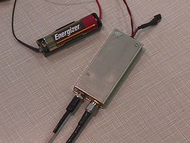
Click to zoom
Application Details
- Equipment Class
- TNT - Licensed Non-Broadcast Transmitter Worn on Body
- Date of Grant
- Sep 30, 1999
- Application Purpose
- Original Equipment
- Date of Application
- Jul 05, 1999
- Equipment Note
- Audio Intelligence Module
- Frequency Range
- 150.00000000 - 174.00000000
- Country
- United States
Documents & Files
Document Text
Text extracted from the exhibit documents filed with the FCC. Open a document above to read the original.
Users Manual
Audio Intelligence Devices, Inc Telephone: (954) 255-2600 (800) 243-1249 FAX: (954) 255-2601 1 of 3 Pages 12301 NW 39 th Street, Coral Springs, Florida 33065 U.S.A. OPERATING INSTRUCTIONS PST-250FL PROGRAMMABLE SYNTHESIZED MINIATURE FLYING LEAD VOICE TRANSMITTER INTRODUCTION AID is the world’s largest manufacturer of electronic surveillance devices. We are proud to be your chosen supplier of intelligence equipment. Our products are available exclusively to certified law enforcement personnel, and are precisely engineered and carefully manufactured to serve your professional needs. This instruction manual explains the correct way to operate the device for optimal performance. To insure reliability, the operator should study this manual before using the equipment. If there are any questions concerning the proper operation or application of any of our products, please contact your personal regional sales representative or our factory for immediate assistance. Courses in the use and techniques of intelligence equipment are available at our National Intelligence Academy, the law enforcement training division of AID. Please call (954) 255-2640 for further course information. CALL: (800) 243-4642 DESCRIPTION The model PST-250FL Programmable Synthesized Miniature Flying Lead Voice Transmitter is a synthesized dual channel, VHF-FM transmitter, operating within a frequency range of 150 – 174 MHz (standard) or special order frequencies of 130 – 150 MHz and 216 – 200 MHz. The RF power output of the PST-250FL is 250 mW (1/4 Watt). The PST-250FL utilizes a built-in (internal) electret microphone, external electret microphone and a set of external antennas. The supplied antennas attach directly to the SMA connector of the PST-250FL. The set consists of three-marked antenna’s covering the band of 150 to 174MHz. Audio Intelligence Devices, Inc Telephone: (954) 255-2600 (800) 243-1249 FAX: (954) 255-2601 2 of 3 Pages 12301 NW 39 th Street, Coral Springs, Florida 33065 U.S.A. For maximum efficiency, the set of antennas are tuned to cover the following frequency ranges: 1. 150MHz through 158MHz 2. 158MHz through 166MHz 3. 166MHz through 174MHz An external 1.5V (type AA) alkaline battery powers the unit. The battery holder is terminated with a polarized female power connector that mates directly with the transmitter’s polarized power male connector. Normal continuous operating time from a fresh battery is better than 3 hours to the half power point. UNPACKING Unpack the unit carefully. If any damage is apparent, notify the shipping company at once. Check to ensure that all components ordered were received. Do not discard shipping carton or packing material. In the event that the unit has to be returned use the original packaging. OPERATION 1. Connect antenna to the PST-250FL SMA connector. Make certain that the proper frequency band of the antenna matches the preprogrammed frequency of the transmitter. 2. The PST-250FL operates with either internal or external electret microphone. NOTE: When an external microphone is inserted into the microphone jack the internal microphone is disabled and the external microphone is enabled. 3. Connect battery power connector to the transmitter power connector. 4. To turn the transmitter “ON”, install the battery into the battery holder with the proper polarization. 5. To turn the transmitter “OFF”, remove the battery from the battery holder. NOTE:Any time the transmitter is in the “ON” position, all nearby conversations will be transmitted. CAUTION:Damage to the transmitter may result if; 1. The external antenna has NOT been connected before the battery has been inserted into the battery holder. 2. The battery is inserted in the battery holder backward (reversed polarity). Audio Intelligence Devices, Inc Telephone: (954) 255-2600 (800) 243-1249 FAX: (954) 255-2601 3 of 3 Pages 12301 NW 39 th Street, Coral Springs, Florida 33065 U.S.A. MAINTENANCE If the transmitter appears to be inoperative, check the following: 1. Check battery for proper voltage. 2. Check that the battery is installed properly. 3. Check that the antenna is installed properly and the correct antenna being used is tuned for the particular frequency of the transmitter. 4. Check that the receiver is on the same frequency as the transmitter.
Cover Letter(s)
Audio Intelligence Devices, Inc. Telephone: (954) 255-2600 (800) 243-1249 FAX: (954) 255-2601 12301 N.W. 39 th Street, Coral Springs, Florida 33065 U.S.A. fcc authorization letter pst120.doc FCC AUTHORIZATION Date: 07/06/99Time: 9:50 To:FCC Authorization & Evaluation Division 7435 Oakland Mills Road Columbia, MD 21045-0429 From:Michael B. McDowellPhone:954-255-2540 Vice President EngineeringFax:954-255-2561 Applicant: Audio Intelligence Devices, Inc. E-Mail: [email protected] Dear Ladies and/or Gentlemen: I appoint Kenneth L. Boston and James Blaha at L.S. Compliance, Inc., to act as an agent in the preparation under Part 15 of the rules and regulations of the Federal Communications Commission. I certify that the exhibitions properly describe the device being submitted under this application and will implement any changes described in the test report. The labels described will be affixed to each item. The following statement is required by the Federal Communications Commission: By checking Yes, the applicant certifies that, in the case of an individual applicant, he or she is not subject to a denial of federal benefits, that included FCC benefits, pursuant to section 5301 of the Anti-Drug Abuse Act of 1988, 21 U.S.C. 853(a), or, in the case of a non-individual applicant (e.g. corporation, partnership, or other unincorporated association), no party to the application is subject to a denial of federal benefits, that included FCC benefits, pursuant to that section. ___X___ YES_______ NO Dated this 6th day of July, 1999. By: Michael B. McDowell Title: Vice President, Engineering / Audio Intelligence Devices, Inc. Phone: 954-255-2540
Cover Letter(s)
. . . . . . . . . . L. S. Compliance, Inc. Date: July 8, 1999 To:FCC – OET From:L. S. Compliance, inc. Jim Blaha Subject: Emission Designator Change to Form 731 This letter is sent to request a change to an in-progress filing to ... Form 731, Item 12, Emission Designator Number Company Name:Audio Intelligence Devices FCC ID # :B348PRPST250 FCC Confirmation # : EA94746 Please change Item 12 of Form 731, Emission Designator ... From:16K6F3E To:15K0F3E Thank you for your time in making this change. Sincerely, Jim Blaha L. S. Compliance, Inc. W66 N220 Commerce Court Cedarburg, Wisconsin 53012 Phone: 414 - 375 - 4400 Fax: 414 - 375 - 4248
External Photos
AID - .25 watt transmitter Closer view of transmitter packaging with connections
External Photos
Audio Intelligence Devices - AID .25 watt Transmitter detailing... Battery Microphone Wire Antenna Metal Case On/Off Termination Switch
External Photos
AID - .25 watt Transmitter Close up of FCC ID Label attached to Transmitter case
ID Label/Location Info
AID - .250 watt Transmitter FCC ID Label
Internal Photos
AID - .25 watt Transmitter Case open for inspection
Internal Photos
AID - .25 watt Transmitter Close-up of Transmitter PCB in the case
Internal Photos
AID - .25 watt Transmitter Close-up of Transmitter PCB removed from case. View is of flip side of PCB
Operational Description
L.S. RESEARCH Inc. 1 HIGH TECHNOLOGY ELECTRONIC CONSULTANTS Confidential WE HAVE DESIGNS ON THE FUTURE W66 N220 Commerce Court, Cedarburg, Wisconsin 53012 • 414-375-4400 • FAX 414-375-4248 Email: [email protected] www.lsr.com Transmitter Theory of Operation The AID PST-250 Transmitter is a miniature, manufacturer-programmable analog voice transmitter. The frequency band of operation is 150-174 MHz with one nominal output power levels of 250 mW. The frequency channels are programmable via a microprocessor and phase-lock loop synthesizer. The frequency programming is a means for the manufacturer to provide custom, fixed frequency transmitters, while maintaining a common hardware platform. The devices are offered as fixed- frequency, fixed-power units. The block diagram of the transmitter is presented below for reference: 1 R 1 N f Dynamic Range Compressor NE 575 Pre- Emphasis Network Pre-AmpMicrophone Crystal Oscillator 10 MHz Frequency Synthesizer LMX1501 Power Amplifier TRF7003 Pre-Amplifier BFG21 VCO NE85633 Switcining DC-DC Converter Transmitter Supply Microcontroller PIC12C508 24LC00 EEProm (16 x 8 bit) CLOCK DATA LATCH EN Power Control Voltage (Filtered PWM) Loop Filter Output Match, Harmonic Filter Antenna Connector The microphone output is presented to an audio chain which provides band-limiting, dynamic range compression/ or automatic leveling control, as well as, pre-emphasis. The output of the audio processing chain is then voltage scaled to directly modulate a phase-locked voltage- controlled-oscillator. The phase-locked-loop bandwidth is narrow and the modulation frequencies are above the natural closed-loop frequency. The output power is controlled by a D.C. bias to the final power amplifier stage. The variable bias is produced by a programmable, filtered, pulse-width-modulation waveform originating at the microcontroller. This power control signal also serves as a delayed transmit enable during power up, to allow the phase-lock-loop to frequency settle before the transmitter is enabled. Once powered up, the transmitter is operated continuously on a single channel and power level until it is powered down.
Schematics
AID - .25 watt Transmitter Schematic
Test Report
L.S. COMPLIANCE, Inc. FCC ID: B348PRPST250 COMPLIANCE TESTING OF AUDIO INTELLIGENCE DEVICES 250 Milliwatt SURVEILLANCE TRANSMITER - Test Report 90196 Tests performed on 23,29 June, 1999 All results of this report relate only to the items that were tested. This report is not to be reproduced, except in full, without written approval of L.S.Compliance, Inc. L. S. COMPLIANCE, Inc. FCC ID: B348PRPST250 LSC 90196Page 2 of 20 Index Description of Measurement Facility p. 3 Section1.1Summary p. 4 1.2Introductionp. 4 1.3Purposep. 4 1.4Radiated Emissions Test Setupp. 5 1.5Radiated Emission Test Procedure p. 5 1.6Test Equipment Used during Testing p. 6 1.7Conducted Emissions Testp. 6 1.8Photos Taken during Testing p. 7 1.9Test Equipment Listp. 8 Appendix A:Calculationsp. 9 B:Data Chartsp. 11 C:Graphs; Signature Scansp. 15 L. S. COMPLIANCE, Inc. FCC ID: B348PRPST250 LSC 90196Page 3 of 20 DESCRIPTION OF MEASUREMENT FACILITIES Site on File With the FCC ID Number: 31040/SIT “ The site referenced above has been found to comply with the test site criteria found in ANSI C63.4-1992 and 47CFR Section 2.948.” L. S. COMPLIANCE, Inc. FCC ID: B348PRPST250 LSC 90196Page 4 of 20 1.1SUMMARY OF TEST REPORT MANUFACTURER:AUDIO INTELLIGENCE DEVICES, Inc MODEL: SERIAL:n/a DESCRIPTION:ELECTRONIC SURVEILLANCE DEVICE FREQUENCY RANGE:TRANSMITTER; 150 MHz TO 174 MHz: upon any assigned channel. The surveillance transmitter was found to meet the radiated spurious emission requirement of FCC part 2.993, to the levels required of FCC part 90.210D, emission mask "D". Prepared/ tested & Approved By: July 1, 1999 Kenneth L. Boston, EMC Lab ManagerDate PE #31926 Registered Professional Engineer (State of Wisconsin) 1.2INTRODUCTION On June 23 and 28 of 1999, a series of Radiated Emissions tests were performed on a sample model of the A.I.D. Surveillance transmitter. These tests were performed using the test procedures outlined in ANSI/TIA/EIA 603-1-1998 for a low power transmitter in the Public Radio service; as called for in section 2.993 for a type accepted device, and in accordance with the limits set forth in FCC Part 90.210. Tests of conducted emissions were also performed in order to verify compliance with the limits set forth in part 90.210 and called out in section 2.991 for a type accepted device. The radiated emission tests were performed by Kenneth L. Boston PE, of L. S. Compliance, Inc. 1.3 PURPOSE The above mentioned tests were performed in order to determine the compliance of the test sample with limits contained in various provisions of Title 47 CFR, including: 90.203 90.210 2.993 All radiated emissions tests were performed to measure the emissions in the frequency bands described by the above sections, and to determine whether said emissions are below the limits established by the above sections. These tests were performed in accordance with the procedure described in the Telecommunications Industry Association publication, TIA/EIA-603 , February 1993, and the addendum, March 1998. General radiated measurement techniques found in ANSI C63.4 were also utilized. Another document used as reference for the EMI receiver specification was the International Special Committee on Radio Interference (CISPR) number 16-1 (1993). L. S. COMPLIANCE, Inc. FCC ID: B348PRPST250 LSC 90196Page 5 of 20 1.4RADIATED EMISSIONS TEST SETUP The test sample was operated within the 3 meter Semi-Anechoic, FCC listed chamber located at L.S. Compliance in Cedarburg, WI. The sample was placed on an 80cm high wooden table, which was centered on the flush-mounted 2m diameter metal turntable. The test sample was operated on its internal battery, and an appropriate passive antenna, 50 ohm dummy load, was connected to the antenna terminals. The transmitter occupies a small P.C board, and for the purposes of this test, was contained inside an integral metal case. The test sample was configured to run in a continuous transmit mode during the radiated measurements. The test sample was set to operate on one of three characteristic frequencies within the Private Land Mobile frequency assignment (Public safety radio pool). One at the low end of the band (150 MHz), one in the middle of the band (162 MHz) and one near the top of the band (174 MHz). Please refer to Section 1.8 for pictures of the test setup. 1.5 RADIATED EMISSIONS TEST PROCEDURE The fundamental and spurious (harmonic) emissions of the transmitter were tested for compliance to Title 47 CFR, FCC Part90.210 limits for transmitters in the Private Land Mobile services, and were also compared with the general limits laid out in Part 15.209. For the calculations used to determine the limits applicable for the test sample, refer to Appendix A. These limits are expressed in decibels below carrier level. (-dBc) The samples were tested from the lowest frequency generated by the transmitter (without going below 9 kHz) to the 10th harmonic of the fundamental frequency generated by the device. The limits described in part 15.209 were also consulted for observation and measurement of spurious signals. The samples were placed on a nonconductive (wooden) pedestal in the 3 Meter chamber and the antenna mast was placed such that the antenna was 3m from the test object. A biconical antenna was used to measure emissions from 30 to 200 MHz, a log periodic was used to measure emissions from 200 to 1000 MHz, and a double ridged waveguide horn was used to measure emissions above 1 GHz. The test object was set to operate in continuous transmit, and the resultant signals were maximized by rotating the turntable 360 degrees, and by raising and lowering the antenna between 1 and 4 meters. The test object was also given several different orientations to determine the maximum signal levels, using both horizontal and vertical antenna polarities. Signal levels found were compared to an equivalent signal level of a generated carrier radiated from a dipole located at the EUT position. No significant emissions were found aside from…
Text truncated - open the document above for the full version.
Test Report
.......... . . . . . . . . . . LS Research Inc. 250 mW Surveillance Transmitter Part 90 Type Acceptance, Conducted Measurements prepared for Audio Intelligence Devices L.S. Research Inc. W66 N220 Commerce Court Cedarburg, WI 53012 Phone 414.375.4400 Fax 414.375.4248 Revision 1.0 L.S. RESEARCH Inc. 2 HIGH TECHNOLOGY ELECTRONIC CONSULTANTS Confidential WE HAVE DESIGNS ON THE FUTURE W66 N220 Commerce Court, Cedarburg, Wisconsin 53012 • 414-375-4400 • FAX 414-375-4248 Email: [email protected] www.lsr.com Table of Contents I.PROJECT INFORMATION ............................................................................................................................. 3 II. FCC CONDUCTED TESTS.............................................................................................................................. 5 A.P ART 90 SUBPART I ........................................................................................................................................... 5 1.90.207 (a) (1) Types of Emmisions (Device Classification) ......................................................................... 5 2.90.209 (a) (5) Bandwidth Limitations (Device Classification, Test Condition). ......................................... 5 3.Part 2.985 Output Power, Part 2.991 Spurious Emissions at Antenna terminals and Part 2.989 Occupied bandwidth using 90.210 (d) Emission Mask for F3E Transmitter. ....................................................................... 6 4.Part 2.995 and 90.213 (a) Frequency Stability........................................................................................... 17 5.90.214: Transient Frequency Behavior. ..................................................................................................... 19 6.2.987 (a), (b) Modulation Characteristics ................................................................................................. 30 III.EQUIPMENT LIST ...................................................................................................................................... 37 IV.EQUIPMENT UNCERTAINTIES .............................................................................................................. 37 V.UNCERTAINTY ANALYSIS .......................................................................................................................... 38 L.S. RESEARCH Inc. 3 HIGH TECHNOLOGY ELECTRONIC CONSULTANTS Confidential WE HAVE DESIGNS ON THE FUTURE W66 N220 Commerce Court, Cedarburg, Wisconsin 53012 • 414-375-4400 • FAX 414-375-4248 Email: [email protected] www.lsr.com Surveillance Transmitter I. Project Information Project: Surveillance Transmitter AID Contact: Company: Audio Intelligence Full Name: John Tepley Job Title: Senior VP of Technical Operations 12301 N.W. Street Coral Springs, FL 33065 Bus: (954) 255-2570 Bus Fax: (954) 255-2531 E-mail: [email protected] Company: Audio Intelligence Full Name: Mike McDowell Job Title: Vice President, Engineering 12301 N.W. Street Coral Springs, FL 33065 Bus: (954) 255-2540 Bus Fax: (954) 255-2531 E-mail: [email protected] Company: Audio Intelligence Full Name: Mark White Job Title: Vice President, Manufacturing Operations 12301 N.W. Street Coral Springs, FL 33065 Bus: (954) 255-2560 Bus Fax: (954) 255-2601 E-mail: [email protected] L.S. RESEARCH Inc. 4 HIGH TECHNOLOGY ELECTRONIC CONSULTANTS Confidential WE HAVE DESIGNS ON THE FUTURE W66 N220 Commerce Court, Cedarburg, Wisconsin 53012 • 414-375-4400 • FAX 414-375-4248 Email: [email protected] www.lsr.com LS Research Contact: Bill Steinike, Operations Manager Mark Wolski, Test Engineer Brian Petted, Vice President of Engineering Voice: 414-375-4400 Fax:414-375-4248 Email: [email protected] Proposal Date:3/9/99 Revision:1.2 Proposal #:859 Proposal File:AID Transmitter 1_2 Job Number:871 Signatures:Brian Petted Technical Approval L.S. RESEARCH Inc. 5 HIGH TECHNOLOGY ELECTRONIC CONSULTANTS Confidential WE HAVE DESIGNS ON THE FUTURE W66 N220 Commerce Court, Cedarburg, Wisconsin 53012 • 414-375-4400 • FAX 414-375-4248 Email: [email protected] www.lsr.com II. FCC Conducted Tests A. Part 90 Subpart I 1. 90.207 (a) (1) Types of Emissions (Device Classification) Classified as an F3E emitter (Frequency Modulation, Analog Modulation, Voice). Power level: 250 mW. The Emission Designator becomes F3E 15K0 2. 90.209 (a) (5) Bandwidth Limitations (Device Classification, Test Condition). 12.5 kHz Nominal Channel Bandwidth L.S. RESEARCH Inc. 6 HIGH TECHNOLOGY ELECTRONIC CONSULTANTS Confidential WE HAVE DESIGNS ON THE FUTURE W66 N220 Commerce Court, Cedarburg, Wisconsin 53012 • 414-375-4400 • FAX 414-375-4248 Email: [email protected] www.lsr.com 3. Part 2.985 Output Power, Part 2.991 Spurious Emissions at Antenna terminals and Part 2.989 Occupied bandwidth using 90.210 (d) Emission Mask for F3E Transmitter. a) Test Requirement: (1) On any frequency from the center of the authorized bandwidth f o to 5.625 kHz removed from f o : Zero dB. (2) On any frequency removed from the center of the authorized bandwidth by a displacement frequency (f d in kHz) of more than 5.625 kHz but no more than 12.5 kHz: At least 7.27(f d -2.88 kHz) dB. (3) On any frequency removed from the center of the authorized band by a displacement frequency (f d in kHz) of more than 12.5 kHz : At least 50 + 10 log (P) dB or 70 dB, whichever is the lesser attenuation. The test condition is presented in Tabular form below. The definition of the spectrum mask as indicated on the spectrum analyzer is also presented, where the display line set to –20 dBm applies to |f m | > 12.5 kHz. 90.210 (d)Absolute Frequency Offset Range: |f m | Attenuation relative to Carrier power P. (1)0 to 5.625 kHz0 dB (2)5.625 kHz to 12.5 kHz7.27(|f m | -2.88) dB (3)> 12.5 kHzMin (50 + 10 log 10 (P) dB ,70 dB) = -20 dBm L.S. RESEARCH Inc. 7 HIGH TECHNOLOGY ELECTRONIC CONSULTANTS Confidential WE HAVE DESIGNS ON THE FUTURE W66 N220 Commerce Court, Cedarburg, Wisconsin 53012 • 414-375-4400 • FAX 414-375-4248 Email: e…
Text truncated - open the document above for the full version.
Test Report
L.S. RESEARCH Inc. HIGH TECHNOLOGY ELECTRONIC CONSULTANTS Confidential To:Jim Blaha, L.S. Compliance, Inc. cc:Federal Communication Commission FCC Filing: EA 94746 FCC ID No. B348PRPST250 From:Mark Wolski, L.S. Research, Inc. Date:August 9, 1999 Subject:Amendment Change to FCC Part 90 – Conducted Emissions Report. The previous report for the Audio Intelligence Devices 250 mW Surveillance Transmitter contained one conducted test condition that failed. Specifically, in the report, Section II-A-5, the transient test condition (FCC Part 90.214) fails at 150 MHz. This failure was repaired with a component value change. The new measured test results for the transient performance are shown on the following pages. The component value change does not affect the compliance in any of the other tests. Please accept this amendment as an update to the conducted emissions report. Specifically, the enclosed pages supercede pages 18 to 28. L.S. RESEARCH Inc. HIGH TECHNOLOGY ELECTRONIC CONSULTANTS Confidential WE HAVE DESIGNS ON THE FUTURE W66 N220 Commerce Court, Cedarburg, Wisconsin 53012 • 414-375-4400 • FAX 414-375-4248 Email: [email protected] www.lsr.com 1 5. 90.214: Transient Frequency Behavior. a) Test Requirement Transmitters designed to operate within the 150 to 174 MHz bands must maintain transient frequencies within the maximum frequency difference during the time intervals indicated in the table below. This device is designed to operate on 12.5 kHz channel bandwidth. The output power of the device is less than 6 Watts, therefore the transient frequency can exceed the limit for the time intervals t on to t 1 and t off to t 3 . The time,t on ,is defined when the transmitter power exceeds –13 dBm at the transmitter output. The modulation domain analyzer is triggered on the envelope of the RF power and the zero time indication is reference to this trigger level. The time, t off , is defined when the transmitter is turned off and the power level falls below –13 dBm. Time IntervalTransient Frequency LimitSettling Time t 1 ±12.5 kHz 5.0 ms t 2 ±6.25 kHz 25.0 ms t 3 ±12.5 kHz 5.0 ms L.S. RESEARCH Inc. HIGH TECHNOLOGY ELECTRONIC CONSULTANTS Confidential WE HAVE DESIGNS ON THE FUTURE W66 N220 Commerce Court, Cedarburg, Wisconsin 53012 • 414-375-4400 • FAX 414-375-4248 Email: [email protected] www.lsr.com 2 b) Test Configuration PC HP53310 Modulation Domain Analyzer Equipment Under Test (Transmitter) Equipment Under Test Configuration Data Capture RF Output HP33150A Arbitrary Waveform Synthesizer Transmitter Enable Signal at 170 milli-Hz 10 dB PAD L.S. RESEARCH Inc. HIGH TECHNOLOGY ELECTRONIC CONSULTANTS Confidential WE HAVE DESIGNS ON THE FUTURE W66 N220 Commerce Court, Cedarburg, Wisconsin 53012 • 414-375-4400 • FAX 414-375-4248 Email: [email protected] www.lsr.com 3 c) Test Conditions and Test Indications Test Condition: 150 MHz, 250 mW. Frequency Up to 100 ms Test Limit: ±12.5 kHz within 5 ms, ±6.25 kHz within 25 ms Test Indication: Transient Frequency < ±6.25 kHz for all times beyond t on . Test Outcome: Transient Frequency within limits → Pass. L.S. RESEARCH Inc. HIGH TECHNOLOGY ELECTRONIC CONSULTANTS Confidential WE HAVE DESIGNS ON THE FUTURE W66 N220 Commerce Court, Cedarburg, Wisconsin 53012 • 414-375-4400 • FAX 414-375-4248 Email: [email protected] www.lsr.com 4 Test Condition: 150 MHz, 250 mW. Frequency Up to 500 ms Test Limit: ±12.5 kHz within 5 ms, ±6.25 kHz within 25 ms Test Indication: Transient Frequency < ±6.25 kHz for all times beyond t on . Test Outcome: Transient Frequency within limits → Pass. L.S. RESEARCH Inc. HIGH TECHNOLOGY ELECTRONIC CONSULTANTS Confidential WE HAVE DESIGNS ON THE FUTURE W66 N220 Commerce Court, Cedarburg, Wisconsin 53012 • 414-375-4400 • FAX 414-375-4248 Email: [email protected] www.lsr.com 5 Test Condition: 150 MHz, 250 mW. Transmitter Release Transient Frequency. Test Limit: ±12.5 kHz within 5 ms of t off Test Indication: Transmitter exhibits no post-release transient behavior, power level drops below –13 dBm. . Test Outcome: Transient Frequency within limits → Pass. L.S. RESEARCH Inc. HIGH TECHNOLOGY ELECTRONIC CONSULTANTS Confidential WE HAVE DESIGNS ON THE FUTURE W66 N220 Commerce Court, Cedarburg, Wisconsin 53012 • 414-375-4400 • FAX 414-375-4248 Email: [email protected] www.lsr.com 6 Test Condition: 162 MHz, 250 mW. Frequency Up to 100 ms Test Limit: ±12.5 kHz within 5 ms, ±6.25 kHz within 25 ms Test Indication: Transient Frequency < ±6.25 kHz for all times beyond t on . Test Outcome: Transient Frequency within limits → Pass. L.S. RESEARCH Inc. HIGH TECHNOLOGY ELECTRONIC CONSULTANTS Confidential WE HAVE DESIGNS ON THE FUTURE W66 N220 Commerce Court, Cedarburg, Wisconsin 53012 • 414-375-4400 • FAX 414-375-4248 Email: [email protected] www.lsr.com 7 Test Condition: 162 MHz, 250 mW. Frequency Up to 500 ms Test Limit: ±12.5 kHz within 5 ms, ±6.25 kHz within 25 ms Test Indication: Transient Frequency < ±6.25 kHz for all times beyond t on . Test Outcome: Transient Frequency within limits → Pass. L.S. RESEARCH Inc. HIGH TECHNOLOGY ELECTRONIC CONSULTANTS Confidential WE HAVE DESIGNS ON THE FUTURE W66 N220 Commerce Court, Cedarburg, Wisconsin 53012 • 414-375-4400 • FAX 414-375-4248 Email: [email protected] www.lsr.com 8 Test Condition: 162 MHz, 250 mW. Transmitter Release Transient Frequency. Test Limit: ±12.5 kHz within 5 ms of t off Test Indication: Transmitter exhibits no post-release transient behavior, power level drops below –13 dBm. . Test Outcome: Transient Frequency within limits → Pass. L.S. RESEARCH Inc. HIGH TECHNOLOGY ELECTRONIC CONSULTANTS Confidential WE HAVE DESIGNS ON THE FUTURE W66 N220 Commerce Court, Cedarburg, Wisconsin 53012 • 414-375-4400 • FAX 414-375-4248 Email: [email protected] www.lsr.com 9 Test Condition: 174 MHz, 250 mW. Frequency Up to 100 ms Test Limit: ±12.5 kHz within 5 ms, ±6.25 kHz within 25 ms Test Indication: Transient Frequency < ±6.25 kHz for all times beyond t on . Test Outcome: Transient Frequency within limits → Pass. L.S. RESEARCH Inc. HIGH TECHNOLOGY ELECTRONIC CONSULTAN…
Text truncated - open the document above for the full version.
Contact Information
Applicant
Mark D. White(Sr. Vice President, Operations)
Technical Contact
Audio Intelligence Devices, Inc.Michael B McDowell
[email protected]954-255-2540
12301 N. W. 39th Street · Coral Springs, Florida · United States
Non-Technical Contact
L. S. Compliance, Inc.James J Blaha
[email protected]414-375-4400
Test Firm
L. S. Compliance, Inc.James Blaha
262-375-4400Fax: 262-375-4248
Technical Specifications
| # | Rule Parts | Frequency Range | Power Output | Emission | Tolerance |
|---|---|---|---|---|---|
| 1 | 90 | 150 MHz - 174 MHz | 250.00 mW | 15K0F3E | 5.0000000000 ppm |
Other Applications from Audio Intelligence Devices, Inc
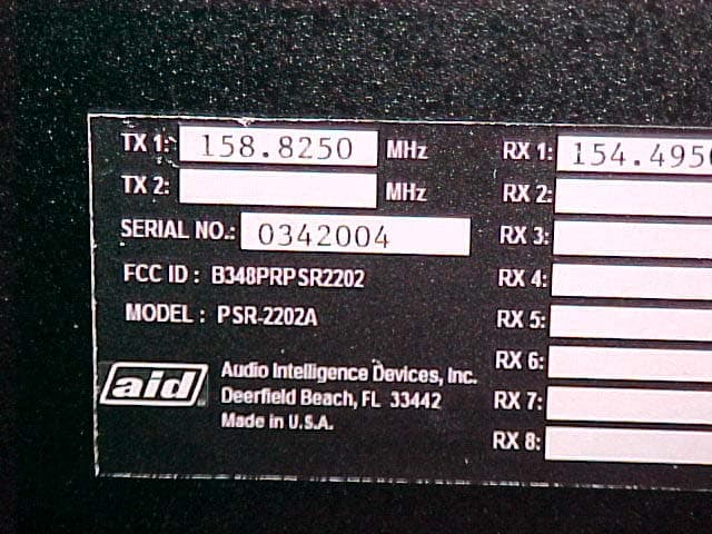
B348PRPSR2202
Feb 01, 2004VHF Repeater
Equipment Class
TNB - Licensed Non-Broadcast Station Transmitter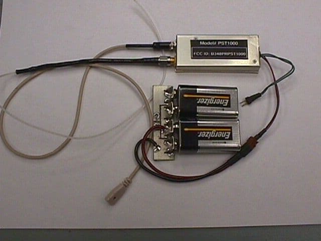
B348PRPST1000
Oct 24, 1999Audio Intelligence Module
Equipment Class
TNT - Licensed Non-Broadcast Transmitter Worn on Body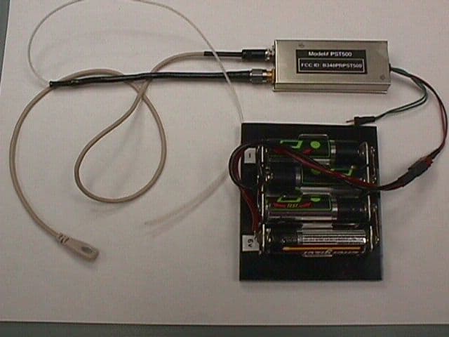
B348PRPST500
Oct 24, 1999Audio Intelligence Module
Equipment Class
TNT - Licensed Non-Broadcast Transmitter Worn on Body
B348PRPST120
Jul 26, 1999Audio Intelligence Module
Equipment Class
TNT - Licensed Non-Broadcast Transmitter Worn on Body
B348PRPST125
Apr 28, 1999Audio Inteligence Module
Equipment Class
TNT - Licensed Non-Broadcast Transmitter Worn on Body