B4OBC5MMFPXBC05 FLASH MODULE
GT-tronics HK Ltd
Click to zoom
Application Details
- Equipment Class
- DSS - Part 15 Spread Spectrum Transmitter
- Date of Grant
- Dec 16, 2012
- Application Purpose
- Original Equipment
- Date of Application
- Dec 16, 2012
- Equipment Note
- BC05 FLASH MODULE
- Frequency Range
- 2402.00000000 - 2480.00000000
- Company
- GT-tronics HK Ltd
- Country
- Hong Kong
Documents & Files
Document Text
Text extracted from the exhibit documents filed with the FCC. Open a document above to read the original.
Users Manual
User Manual BC5MMFP(B,C) Class2 Bluetooth Module (This module is limited to OEM Installation only) Features Class 2 module with printed PCB antenna 8Mbit (optional 16Mbit) Flash Fully Qualified Bluetooth 2.1 + EDR CSR BC5MM-EXT chip Low current consumption 3.3V operation High quality 95db SNR on DAC playback PCM digital audio input/output (BC5MMFPC only) Support single/dual-mic input Interface: PIOs, UART, SPI for programming Built-in DSP Co-Processor for audio signal processing Support of noise and echo cancellation Configurable 5-band EQ 802.11 Co-existence A2DP, AVRCP, HSP, HFP profile support Optional iAP, SPP profile support for app communication Optional AAC, MP3 direct streaming and SRS WoWHD Optional NFC pairing support RoHS compliant Dimension: 34.0 x 12.0 x 2.2 mm Applications High Quality Mono/Stereo Wireless Headsets Hands-Free Car Kits Wireless Speakers Home-theater Sound Bar Bluetooth-Enabled Wireless Gateways Block Diagram BC5MMFPB(C) is a Class 2 Bluetooth sub-system using BlueCore5 –Multimedia Ext Flash chipset from leading Bluetooth chipset supplier Cambridge Silicon Radio. .It interfaces to a 8/16 MBit parallel Flash. The software stack running on the BlueCore5 MM Ext chipset is fully compliant to Bluetooth Specification v2.1 + EDR. BC5MMRPB(C) also has necessary balun and bandpass filters to interface with a build-in PCB antenna, which forms a very cost effective radio subsystem. Applications Example The above schematic shows a typical application of BC5MMFPB (C) module. Double click on the diagram to see the detail drawings. Power supply The whole module shall be supplied with a clean 3.3v at its 3V3 power port (pin #9). A coupling capacitor should be placed as close to this pin as possible. All others PIO pins (including VREG), SPI programming port and UART port will run at this power rail. Differential Audio Outputs The output stage digital circuitry converts the signal from 16-bit per sample, linear PCM of variable sampling frequency to bit stream, which is fed into the analogue output circuitry. The output stage circuit comprises a DAC with gain setting and class AB output stage amplifier. The output is available as a differential signal between SPK_LN and SPK_LP for the left channel, as the schematic shows, and between SPK_RN and SPK_RP for the right channel. The output stage is capable of driving a speaker directly when its impedance is at least 8Ω. PCM Interface (BC5MMFPC only) The audio PCM interface supports continuous transmission and reception of PCM encoded audio data over Bluetooth. PCM is a standard method used to digitise audio, particularly voice, for transmission over digital communication channels. Through ts PCM interface, BlueCore5‑Multimedia External has hardware support for continual transmission and reception of PCM data, so reducing processor overhead. BlueCore5‑Multimedia External offers a bidirectional digital audio interface that routes directly into the baseband layer of the on-chip firmware. It does not pass through the HCI protocol layer. Hardware on BlueCore5‑Multimedia External allows the data to be sent to and received from a SCO connection. Up to 3 SCO connections can be supported by the PCM interface at any one time. BlueCore5‑Multimedia External can operate as the PCM interface master generating PCM_SYNC and PCM_CLK or as a PCM interface slave accepting externally generated PCM_SYNC and PCM_CLK. BlueCore5‑Multimedia External is compatible with various clock formats, including Long Frame Sync, Short Frame Sync and GCI timing environments. Host Information This module was defined to be used for specific host only. The designated host for this module was: Company: GT-tronics HK Ltd. Address: B202, Tonic Industrial Center, 19 Lam Hing Street, Kowloon Bay, Hong Kong Host Model Name: BTSPK Host brand name: GT-tronics UART Port BC5MMFPB (C) has a standard UART serial interface that provides a simple mechanism for communicating with other serial devices using the RS232 protocol. When BC5MMFPB (C) is connected to another digital device, RX and TX transfer data between the 2 devices. UART configuration parameters, such as baud rate and packet format, are set using BlueCore5‑Multimedia External firmware. To communicate with the UART at its maximum data rate using a standard PC, an accelerated serial port adapter card is required for the PC. Possible UART Settings Parameter Possible values Baud rate Minimum 1200 baud (≤2%Error) Maximum 9600 baud (≤1%Error) Parity None, Odd or Even Number of stop bits 1 or 2 Bits per byte 8 SPI Programming Port The SPI is used to program and configuration, and debug the BlueCore5‑Multimedia External. It is required in production. Ensure the 4 SPI signals are brought out to either test points or a header. Note that these four signals are run at 3.3v power rail. Mic Inputs The microphone bias, MIC_BIAS, derives its power from the 3V3 power port and requires a 4.7μF capacitor on its output. The MIC_BIAS is like any voltage regulator and requires a minimum load to maintain regulation. The MIC_BIAS maintains regulation within the limits 0.200mA to 1.230mA. The input impedance at MIC_A_N, MIC_A_P, MIC_B_N and MIC_B_P is typically 6.0kΩ . LED Drivers BC5MMFPB (C) includes 2 pads dedicated to driving LED indicators. Both terminals can be controlled by firmware, The terminals are open-drain outputs, so the LED must be connected from a positive supply rail to the pad in series with a current limiting resistor. It is recommended that the LED pad, LED[0] or LED[1] pins, operate with a pad voltage below 0.5V. In this case, the pad is like a resistor, RON . The resistance together with the external series resistor sets the current in the LED. Buttons The example application has assigned the following functions to each PIO pins: PIN NAME Function Descriptions 13 PIO14 REV Select previous song, fast rewind. 32 PIO12 FWD Select next song, fast forward 33 PIO11 PLAY_PAUSE Play / …
Text truncated - open the document above for the full version.
Cover Letter(s)
COVER LETTER The BC5MMFPX Module has been granted as Limited modular approval for portable applications. Integrators may use the BC5MMFPXModule in their final products without additional FCC certification if they meet the following conditions. Otherwise, additional FCC approvals must be obtained. 1.To comply with FCC regulations limiting both maximum RF output power and human exposure toRF radiation, the maximum antenna gain including cable loss in a mobile-only exposure condition must not exceed 0dBi in the 2.4G band. 2.The BC5MMFPX Module and its antenna must not be co-located or operating in conjunction with any other transmitter orantenna within a host device. 3.A label must be affixed to the outside of the end product into which the BC5MMFPX Module is incorporated, with a statement similar to the following: This device contains FCC ID: B4OBC5MMFPX. 4.A user manual with the end product must clearly indicate the operating requirements and conditions that must be observed to ensure compliance with current FCC RF exposure guidelines. 5. OEM integrators and end-users must be provided with transmitter operation conditions for satisfying RF exposure compliance. 6. This device is sold to OEM integrators and the OEM integrators are instructed to ensure that the end user has no manual instructions to remove or install the device. The end product with an embedded BC5MMFPX Module may also need to pass the FCC Part 15 unintentional emission testing requirements and be properly authorized per FCC Part 15. Thank you for your attention to this matter. Yours Sincerely, Dennis Wong Admin Asst
External Photos
External Photos
ID Label/Location Info
FCC ID: B4OBC5MMFPX Label Label Location FCC ID LABEL LOCATION
Internal Photos
Internal Photos
Internal Photos
External Photos
Test Report
SZ12060182W01 Page 2 of 83 DIRECTORY 1. GENERAL INFORMATION .................................................................................................... 3 1.1. EUT Description ....................................................................................................................... 3 1.2. Test Standards and Results ........................................................................................................ 4 1.3. Facilities and Accreditations ..................................................................................................... 5 2. 47 CFR PART 15C REQUIREMENTS .................................................................................... 6 2.1. Antenna requirement ................................................................................................................. 6 2.2. Number of Hopping Frequency ................................................................................................ 6 2.3. Peak Output Power.................................................................................................................. 11 2.4. 20dB Bandwidth ..................................................................................................................... 13 2.5. Carried Frequency Separation ................................................................................................. 20 2.6. Time of Occupancy (Dwell time) ........................................................................................... 23 2.7. Conducted Spurious Emissions ............................................................................................... 30 2.8. Band Edge ............................................................................................................................... 42 2.9. Conducted Emission ............................................................................................................... 60 2.10. Radiated Emission................................................................................................................... 63 2.11. RF exposure evaluation ........................................................................................................... 83 Change History Issue Date Reason for change 1.0 Aug 31, 2012 First edition SZ12060182W01 Page 3 of 83 1. General Information 1.1. EUT Description EUT Type ............................. : BC05 Flash module Serial No. .............................. : (n.a, marked #1 by test site) Hardware Version ................. : 1.0 Software Version .................. : Applicant .............................. : Manufacturer ........................ : 1.0 GT-tronics HK Ltd B202, Tonic Industrial Center, 19 Lam Hing Street, Kowloon Bay, Hong Kong GT-tronics HK Ltd B202, Tonic Industrial Center, 19 Lam Hing Street, Kowloon Bay, Hong Kong Frequency Range .................. : The frequency range used is 2402MHz - 2480MHz (79 channels, at intervals of 1MHz); The frequency block is 2400MHz to 2483.5MHz. Modulation Type .................. : Bluetooth: FHSS (GFSK(1Mbps), ∏/4-DQPSK(EDR 2Mbps), 8-DPSK(EDR 3Mbps)) Antenna Type ........................ : PCB Antenna Antenna Gain ........................ : 0dBi Note 1: The EUT is a BC05 Flash module, it contains Bluetooth Module operating at 2.4GHz ISM band; the frequencies allocated for the Bluetooth Module is F(MHz)=2402+1*n (0<=n<=78). The lowest, middle, highest channel numbers of the Bluetooth Module used and tested in this report are separately 0 (2402MHz), 39 (2441MHz) and 78 (2480MHz). Note 2: For a more detailed description, please refer to Specification or User’s Manual supplied by the applicant and/or manufacturer. Note 3: a. When power on, the EUT will scan the whole frequency until a Connection command from the other BT devices. b. When receiving the signal from the other BT devices, The EUT transmit aresponse signal. c. The other devices receive the response signal and recognize it, then send a connection command to establish the connection. d. After the connection establish successfully, the data transmission is beginning. At the same time, the both devices will shift frequencies in synchronization per a same pseudo randomly ordered list of hopping frequencies, the hopping rate is1600 times per second. This device conforms to the criteria in FCC Public Notice DA 00-705. e. The bandwidth of the receiver, which is set to a fixed width by the software. Note 4: Bluetooth signal has 9 packages DH1, DH3, DH5, 3DH1, 3DH3, 3DH5, 5DH1, 5DH3, 5DH5, DH5 package is largest, we are testing DH5 in the document. Note5: The antenna of EUT is designed with permanent attachment and no consideration of replacement, it is printed on the circuit board with a maximum gain of 0dBi, and it is used to radiate the RF emissions SZ12060182W01 Page 4 of 83 1.2. Test Standards and Results The objective of the report is to perform testing according to 47 CFR Part 15 Subpart C (Bluetooth, 2.4GHz ISM band radiators) for the EUT FCC ID Certification: No. Identity Document Title 1 47 CFR Part 15 (10-1-09 Edition) Radio Frequency Devices Test detailed items/section required by FCC rules and results are as below: No. Section in CFR 47Description Result 1 15.203 Antenna Requirement PASS 2 15.247(a) Number of Hopping Frequency PASS 3 15.247(b) Peak Output Power PASS 4 15.247(a) 20dB Bandwidth PASS 5 15.247(a) Carrier Frequency Separation PASS 6 15.247(a) Time of Occupancy (Dwell time) PASS 7 15.247(d) Conducted Spurious Emission PASS 8 15.247(d) Band Edge PASS 9 15.207 Conducted Emission PASS 10 15.209 15.247(c) Radiated Emission PASS NOTE: The tests were performed according to the method of measurements prescribed in DA-00-705. SZ12060182W01 Page 5 of 83 1.3. Facilities and Accreditations 1.3.1. Facilities Shenzhen Morlab Communications Technology Co., Ltd. Morlab Laboratory is a testing organization accredited by China National Accreditation Service for Conformity Assessment (CNAS) according to ISO/IEC 1702…
Text truncated - open the document above for the full version.
Test Setup Photos
Test Setup Photos 1. CE 2.RE 3. CSE
Contact Information
Applicant
Dennis Wong(Admin Asst)
Test Firm
Shenzhen Morlab Communications Technology Co., LtdIvy zhu
Technical Specifications
| # | Rule Parts | Frequency Range | Power Output |
|---|---|---|---|
| 1 | 15C | 2.40 GHz - 2.48 GHz | 3.00 mW |
Other Applications from GT-tronics HK Ltd
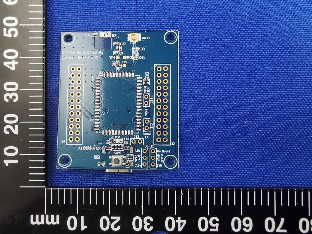
B4O-QC35XFNX
Aug 27, 2023GT-tronics QCC Bluetooth Module
Equipment Class
DSS - Part 15 Spread Spectrum Transmitter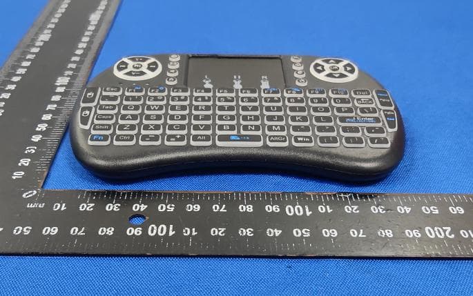
B4O-MINIWKB
Apr 06, 2022Mini Wireless Keyboard
Equipment Class
DXX - Part 15 Low Power Communication Device Transmitter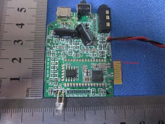
B4OBC86XRPA
Aug 04, 2013BC865RPA BLUETOOTH MODULE
Equipment Class
DSS - Part 15 Spread Spectrum Transmitter