B4Z-764A-SMOKE
UTC Fire & Security Americas Corporation, Inc.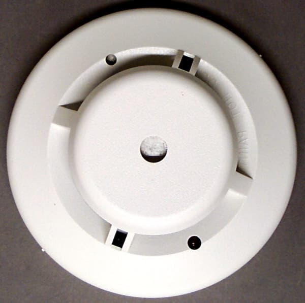
Click to zoom
Application Details
- Equipment Class
- DSC - Part 15 Security/Remote Control Transmitter
- Date of Grant
- Oct 14, 1999
- Application Purpose
- Original Equipment
- Date of Application
- Aug 18, 1999
- Frequency Range
- 319.50000000 - 319.50000000
- Country
- United States
Documents & Files
Document Text
Text extracted from the exhibit documents filed with the FCC. Open a document above to read the original.
Users Manual
Page 1 System Sensor Smoke Sensor System Sensor Smoke Sensor Model 2100ARFT Document Number: 466-xxxx Rev. A PRELIMINARY August 1998 INSTALLATION INSTRUCTIONS Product Summary The System Sensor™ Smoke Sensor Model 2100ARFT (smoke alarm) is a Learn Mode, wireless, photoelectric smoke sensor with a self-contained alarm siren, a low- battery annunciator, and a status light. The smoke alarm is part of a security/fire alarm system and com- municates with the system’s control panel. Figure 1 illustrates the smoke sensor’s parts. Installation Guidelines νAvoid installing the unit until all contsruction is completed. The mounting ring may be pre- installed. νLeave the orange dust cover on the unit until sheet rocking and sanding are completed; other- wise, dust can get into the unit and cause false alarms. CAUTION:The orange dust cover must be removed for the unit to detect smoke. νDo not mix battery brands. νNot compatible with CareTaker Plus or custom versions with software versions 3.0 or earlier. νNot compatible with Commander 2000 or custom versions with software versions 4.0 or earlier. (The Commander 2000 announces the version when it is powered up or reset.) Tools Needed νPhillips screwdriver and pocket-sized slotted screwdriver Batteries UL Note:Each smoke alarm uses two 3-volt lithium batteries. For UL installations, use one of the following: Sanyo CR123A, Panasonic CR123A, or Duracell DL123A. Do not mix brands. Inserting Batteries The batteries must be correctly installed before the panel can learn the smoke alarm ID. [Batteries are shipped in the unit backwards.] You must remove them and reinstall them correctly. To insert batteries into the smoke sensor: 1.Gently twist the cover counterclockwise to sepa- rate it from the mounting bracket. 2.Remove the batteries from the battery compart- ment. 3.Insert the batteries into the battery compartment. Observe proper polarity. 4.Leave the mounting ring off and proceed to “Learning the Smoke Sensor.” Low Batteries When the batteries need to be replaced, the unit trans- mits a signal to the panel. If the batteries are not replaced within 7 days, the unit will chirp every 40 seconds until the batteries are exhausted. Note: If you test the smoke alarm or it goes into alarm during this 7-day period, chirp delay is canceled and the unit begins chirping immedi- ately. Programming For more detailed programming information, refer to the specific panel’s installation manual. 60-838-95 EXHIBIT G Page 2 System Sensor Smoke Sen- CAUTION:If the smoke sensor is attached to the mounting bracket, the panel cannot learn the ID. To add the smoke alarm to panel memory: 1.Put the panel in Program Mode/Learn Sensors. 2.Select a group and sensor number. 3.Use a pencil or small screwdriver to press the smoke alarm test button for at least one second. The panel will indicate that the sensor has been learned. If you release the test button in less than 2.5 seconds, the smoke alarm siren will not sound. Mounting Guidelines Determine the best mounting location for the smoke alarm using the following guidelines: UL Note:DO NOT mount a smoke alarm to a drop ceiling tile; mount it to a metal runner. νMount all smoke alarms within 100 feet of the panel. νInstall a minimum of two smoke alarms in any household, no matter how small it is. νPut a smoke alarm in the hallway outside of every bedroom area. A minimum of two smoke alarms are required in homes with two bedroom areas (see Figure 4). A78-1171-02 Figure 1. Residence with multiple sleeping areas. νPut a smoke alarm on every level of a multi-level residence (Figure 5). νInstall basement alarms on the ceiling at the bot- tom of the basement stairwell. Figure 2. Multi-level residence. νInstall smoke alarms on the ceiling as close to the center of the room as possible. If this is not practi- cal, install it on the ceiling no closer than 4 inches (10 cm) from any wall or corner (Figure 6). νIf ceiling mounting is not practical, install on an inside wall between 4 and 6 inches (10 and 15 cm) from the ceiling (Figure 6). νPut smoke alarms at both ends of a bedroom hall- way if the hallway is more than 30 feet (9 meters) long. Large rooms over 900 square feet require more than a single sensor. Figure 3. Smoke alarm mounting locations. νAreas with rough ceilings or short, transom-type walls coming down from the ceiling require addi- tional smoke alarms. νInstall second-floor smoke alarms on the ceiling at the top of the first-to-second floor stairwell. Be sure no door or other obstruction blocks the path of smoke to the unit. νIn rooms with sloped, peaked, or gabled ceilings, install smoke alarms 3 feet (0.9 meter) measured down on the slant from the highest point of the ceiling (Figure 7). BEDROOM SMOKE DETECTORS FOR MINIMUM PROTECTION SMOKE DETECTORS FOR MORE PROTECTION AND REQUIRED IN NEW CONSTRUCTION BEDROOM BEDROOM LIVING ROOM DINING ROOM KITCHENFAMILY ROOM BEDROOM BEDROOMBEDROOM LIVING ROOM KITCHEN BASEMENT GARAGE SMOKE DETECTORS FOR MINIMUM PROTECTION SMOKE DETECTORS FOR MORE PROTECTION AND REQUIRED IN NEW CONSTRUCTION BEST LOCATION ACCEPTABLE LOCATION DEAD AIR SPACE BEST IN CENTER OF CEILING NO CLOSER THAN 4 " (10 cm) FROM SIDE WALL MOUNT ON WALL AT LEAST 4 " (10 cm) FROM CEILING NO MORE THAN 6 " (15 cm) FROM CEILING System Sensor Smoke Sensor Page 3 Figure 4. Sloped, peaked, or gabled ceilings. Do not install smoke alarms in the following loca- tions: νIn or near areas where combustion particles are normally present such as kitchens; in garages where there are particles of combustion in vehicle exhausts; near furnaces, hot water heaters, or gas space heaters. νOn the ceiling in rooms next to kitchens where there is no transom between the kitchen and these rooms. νIn damp or very humid areas, or next to bath- rooms with showers. Install sensors at least 5 feet (1.5 meters) away from bathrooms. νIn very cold or very hot areas. νIn dusty, dirty, or insect-infested areas. νNea…
Text truncated - open the document above for the full version.
Block Diagram
Interactive Technologies Inc 08/27/99 2:16 PM FCC ID: B4Z-764A-SMOKE Page 1 of 1 G:\USERS\SOUTHER\Production Doc\transfer\Bergman\764a_smoke\wrd\exhibitC.DOC
External Photos
Interactive Technologies Inc 08/27/99 1:36 PM FCC ID: B4Z-764A-SMOKE Page 1 of 3 \\CORP1\SYS\MANUFACT\ITIVOL1\USERS\SOUTHER\Production Doc\transfer\Bergman\764a_smoke\wrd\exhibitB.DOC Interactive Technologies Inc exhibitB.DOC 08/27/99 1:36 PM FCC ID: B4Z-764A-SMOKE Page 2 of 3 Interactive Technologies Inc exhibitB.DOC 08/27/99 1:36 PM FCC ID: B4Z-764A-SMOKE Page 3 of 3
ID Label/Location Info
Interactive Technologies Inc 08/27/99 1:30 PM FCC ID: B4Z-764A-SMOKE Page 1 of 1 \\CORP1\SYS\MANUFACT\ITIVOL1\USERS\SOUTHER\Production Doc\transfer\Bergman\764a_smoke\wrd\exhibitA.DOC
Internal Photos
Interactive Technologies Inc 08/27/99 1:13 PM FCC ID: B4Z-764A-SMOKE Page 1 of 4 G:\USERS\SOUTHER\Production Doc\transfer\Bergman\764a_smoke\wrd\exhibit.DOC Interactive Technologies Inc exhibit.DOC 08/27/99 1:13 PM FCC ID: B4Z-764A-SMOKE Page 2 of 4 Interactive Technologies Inc exhibit.DOC 08/27/99 1:13 PM FCC ID: B4Z-764A-SMOKE Page 3 of 4 Interactive Technologies Inc exhibit.DOC 08/27/99 1:13 PM FCC ID: B4Z-764A-SMOKE Page 4 of 4
Operational Description
Interactive Technologies Inc 08/25/99 9:41 AM FCC ID: B4Z-764A-SMOKE G:\Users\Souther\Production Doc\transfer\Bergman\764a_smoke\wrd\OP_DESC.DOC Product Description The product is a wireless smoke alarm (detector) used in conjunction with a wireless security alarm system. The smoke alarm unit monitors the environment for the presence of smoke, abnormally high temperature, or sudden increase in temperature. If any of these conditions, which are indicative of a fire, are found, the unit goes into alarm. In alarm the unit will sound its internal siren and transmit an alarm message to the security alarm panel. The panel will then sound its sirens, and call the monitoring station for help. While in alarm, the unit will transmit the alarm condition every minute to be sure the signal gets through. Normally the unit only transmits supervisory signals every hour. This product is the combination of a smoke alarm manufactured by System Sensor, a division of Pittway, and the transmitter manufactured by ITI. ITI has code imbedded in the microcontroller of the smoke detector to control the transmitter. The microcontroller used is a National Semiconductor COP8. The RF circuit consists of a 106.5 MHz oscillator followed by an amplifier. The amplifier is turned on and off to modulate the carrier. EXHIBIT I Operational Description
Schematics
Interactive Technologies Inc 08/27/99 2:05 PM FCC ID: B4Z-764A-SMOKE Page 1 of 2 \\CORP1\SYS\MANUFACT\ITIVOL1\USERS\SOUTHER\Production Doc\transfer\Bergman\764a_smoke\wrd\exhibitD.DOC Interactive Technologies Inc exhibitD.DOC 08/27/99 2:05 PM FCC ID: B4Z-764A-SMOKE Page 2 of 2
Test Report
Interactive Technologies Inc 08/27/99 12:49 PM FCC ID: B4Z-764A-SMOKE Page 1 of 21 \\CORP1\SYS\MANUFACT\ITIVOL1\USERS\SOUTHER\Production Doc\transfer\Bergman\764a_smoke\wrd\FCC_REPT2.DOC Interactive Technologies, Inc. System Sensor 2100 ARFT Smoke Alarm B4Z-764A-SMOKE Certification Interactive Technologies Inc FCC_REPT2.DOC 08/27/99 12:49 PM FCC ID: B4Z-764A-SMOKE Page 2 of 21 System Sensor 2100 ARFT Smoke Alarm B4Z-764A-SMOKE 8/19/1999 Interactive Technologies, Inc. 2266 North Second Street North Saint Paul, MN 55109 (651) 777-2690 Interactive Technologies Inc FCC_REPT2.DOC 08/27/99 12:49 PM FCC ID: B4Z-764A-SMOKE Page 3 of 21 1. INTRODUCTION4 2. STATEMENT OF COMPLIANCE4 3. LAB MEASUREMENTS DISCUSSION / TEST NOTES7 3.1 Test Notes7 3.1.1 Transmissions shall cease within 5 seconds of activation [ §15.231(a)(2) ]7 3.1.2 Supervisory Calculation [ §15.231(a)(3) ]9 3.1.3 Duty Cycle Correction Factor [§15.231(b)(2) and §15.35(c)]9 3.1.4 Bandwidth Measurement [ §15.231(c) ]12 3.1.5 Emissions Measurements16 3.1.5.1 Radiated Emissions Summary16 3.1.5.2 FCC Emissions Calculation16 3.1.5.2.1 Terms16 3.1.5.2.2 Example Calculation16 3.1.5.3 Radiated Emissions17 3.1.5.4 Forbidden Bands17 Interactive Technologies Inc FCC_REPT2.DOC 08/27/99 12:49 PM FCC ID: B4Z-764A-SMOKE Page 4 of 21 1. Introduction This device is a wireless fire alarm transmitter for use in a wireless security system. The unit is self-contained and powered by two 3.0 Volt Lithium batteries. The transmitter’s frequency is crystal controlled and is not adjustable by the user. The device measures approximately 5′′ in diameter and 2′′ in height. The unit weighs approximately 6.5 ounces without batteries. We are requesting Certification under FCC Rules, Part 15, Subpart C, Paragraph 15.231. Please send comments/suggestions on the report format to [email protected]. 2. Statement of Compliance §2.907Certification This is an application for certification §2.911Application a)This is an application and has been filed electronically with form 731. b)All information required has been supplied. c)The applicant has signed the application (electronically). d)The technical data has been signed. (See Radiated Emissions) e)Applicant signature block on electronic form 731 completed by officer of the company or authorized company personnel. f) The appropriate fee has been paid electronically with VISA on 8/19/99. §2.915Grant This application demonstrates that all applicable technical standards have been met and a grant of this application will serve the public interest. §2.925Label Each piece of equipment for which authorization will be granted will be uniquely identified with “FCC ID: B4Z-764A-SMOKE.” The required statement will appear with the FCC ID on the product and, although not required, in the installation instructions. See Exhibit A, PDF file id_label.pdf Interactive Technologies Inc FCC_REPT2.DOC 08/27/99 12:49 PM FCC ID: B4Z-764A-SMOKE Page 5 of 21 §2.947Measurement Procedure a)The measurement procedure follows ANSI C63.4 procedure. Procedural notes are contained in the laboratory report. d)A list of test equipment used is contained in the laboratory report. §2.948Description of Measurement Facilities Measurements were performed at TUV Testing Services Open Test Site. The FCC keeps a full description of the measurement facilities on file. TUV’s acceptance and approval is dated as December 5, 1993 in a letter received from the FCC. The address of the test facility is: TUV Product Service 19035 Wild Mountain Road Taylors Falls, MN 55084-1758 Phone: 651-638-0297 Contact:Joel Schneider Test Engineer in Charge See Exhibit F, PDF file test_pho.pdf for sketch of measurement setup §2.1033Application for Certification a)Form 731 has been electronically filed on 8/19/99. Items that did not apply were left blank. b)This technical report contains the following information where applicable. 1)Full name and mailing address of manufacturer and applicant for certification: Interactive Technologies Inc 2266 North Second Street North Saint Paul, MN 55109 2)FCC Identifier: B4Z-764A-SMOKE 3)Copy of installation instructions: See Exhibit G, PDF file: user_man.pdf 4)Brief Description of circuit functions and device operation: See Exhibit I, PDF file op_desc.pdf See Exhibit D, PDF file schemat.pdf for schematics (page 1) and parts placement (page 2) diagrams. Interactive Technologies Inc FCC_REPT2.DOC 08/27/99 12:49 PM FCC ID: B4Z-764A-SMOKE Page 6 of 21 5) Block Diagram See Exhibit C, PDF file block.pdf. 6)Report of the measurements of radiation and conducted emissions: This document. 7)Photographs External: See Exhibit B, PDF file extern.pdf Internal: See Exhibit H, PDF file intern.pdf 8)Peripheral or Accessory devices: This is not applicable since this device is stand-a- lone product. 9) Transition Rules This application is not pursuant to the transition rules of §15.37 10)Emergency Broadcast decoding: This is not applicable to device in this application. 11)Application for direct sequence spread spectrum devices... This is not applicable to device in this application. 12)Application for scanning receivers... This is not applicable to device in this application. c)Composite Systems This is not applicable to device in this application. Interactive Technologies Inc FCC_REPT2.DOC 08/27/99 12:49 PM FCC ID: B4Z-764A-SMOKE Page 7 of 21 3. Lab Measurements Discussion / Test Notes 3.1 Test Notes 3.1.1 Transmissions shall cease within 5 seconds of activation [ §15.231(a)(2) ] In the event of a smoke alarm, 8 packets are sent in the transmission. The packet duration is, at most, 30 mS, see Duty Cycle Correction Factor [§15.231(b)(2) and §15.35(c)]. The time between packets random between 100 mS and 450 mS so the length of the longest transmission is: 8*30mS + 7*450mS = 3.39 seconds. So long as the fire alarm condition is present, the device will re-transmit every minute as allowed in §15.231(a)(4). The following plot shows an 8-packet transmission that concludes in …
Text truncated - open the document above for the full version.
Test Setup Photos
Interactive Technologies Inc 08/25/99 9:41 AM FCC ID: B4Z-764A-SMOKE G:\Users\Souther\Production Doc\transfer\Bergman\764a_smoke\wrd\TEST_PHO.DOC 0.8 Meters EUT Receiving Antenna 3 Meters EXHIBIT F Test Setup Sketch for Radiated Emissions 1 Meter
Contact Information
Applicant
Konstantin Khrustov(Compliance Leader)
Technical Contact
Ineractive Technologies IncJohn T Bergman
[email protected]800-777-1415
2266 North Second St · North Saint Paul, Minnesota · United States
Test Firm
TUV SUD America - Product ServiceJoel Schneider
Technical Specifications
| # | Rule Parts | Frequency Range | Power Output |
|---|---|---|---|
| 1 | 15C | 319.5 MHz - 319.5 MHz | - |
Other Applications from UTC Fire & Security Americas Corporation, Inc.

B4Z-944-3G
May 04, 2015AV-3G
Equipment Class
PCB - PCS Licensed Transmitter
B4Z-962-BT
May 04, 2015AVO-BT
Equipment Class
DSS - Part 15 Spread Spectrum Transmitter
B4Z-959-ZW
Apr 29, 2015AVO-ZW
Equipment Class
DXT - Part 15 Low Power Transceiver, Rx Verified
B4Z-958-BTWI
Apr 29, 2015AVO-BTWIFI
Equipment Class
DTS - Digital Transmission System
B4Z-680F-PIR
Dec 01, 2014PIR Security System Transmitter
Equipment Class
DSC - Part 15 Security/Remote Control Transmitter