B4Z-903-TCVR319.5 MHz OEM Transceiver w/Crystal TX
UTC Fire & Security Americas Corporation, Inc.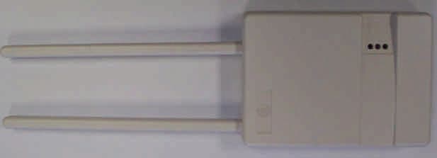
Click to zoom
Application Details
- Equipment Class
- DSR - Part 15 Remote Control/Security Device Transceiver
- Date of Grant
- Aug 30, 2005
- Application Purpose
- Original Equipment
- Date of Application
- Jul 27, 2005
- Equipment Note
- 319.5 MHz OEM Transceiver w/Crystal TX
- Frequency Range
- 319.50000000 - 319.50000000
- Country
- United States
Documents & Files
Document Text
Text extracted from the exhibit documents filed with the FCC. Open a document above to read the original.
Users Manual
466-2226B May 2005 600-1025 OEM Transceiver Module Installation Instructions Description The OEM transceiver modules are compatible with GE Security wireless transmitters. The modules have an onboard receiver, microprocessor, and connection for a daughter board. The micro- processor controls the receiver, providing antenna switching and AGC functions. It also analyzes the received data from the receiver, validates incoming packets, and returns packets to the receiver when polled. A daughter board, which communicates with the module via an 8-pin header, can be added to implement a variety of functions. Each module encapsulates the receiver functions and formats and presents a common interface to the daughter board. Therefore, even though protocols vary among the GE Security radio frequencies used around the world, the interface is the same to the daughter board. Installation guidelines Observe the following guidelines when installing the OEM trans- ceiver module: • Allow at least 9 inches (22.9 cm) of clearance above the enclosure for the antennas. • Avoid mounting locations that expose the module to mois- ture. • Avoid areas with excessive metal or electrical wiring including furnace and utility rooms. If unavoidable, mount on or near metal with the antenna extending above the metallic surfaces as shown in Figure 1. Figure 1.Mounting on or near metal Note: For UL installations this module must be mounted in the 600- 1029 enclosure. Daughter boards have not been investigated for use by UL. Installation To mount the OEM transceiver module onto the back plate of the 600-1029 enclosure, do the following: 1.Insert the antennas into the antenna shrouds (Figure 2). 2.Gently slide the top of the circuit board under the two top latches. 3.Snap the circuit board in at the bottom latch to secure it in place as shown in Figure 2. Figure 2.Installing the circuit board 4.Connect DC power to the OEM transceiver module using 2 mm power jacks (center positive) or connect flyleads to the terminal block as labeled on the board. Note: For model 600-1025-02-43, the cable length must be less than 3 m (9.8 ft.) for CE compliance. LED operation Table 1 shows the LED indications for the OEM transceiver module. Troubleshooting The following table gives troubleshooting suggestions for the OEM transceiver module. CAUTION You must be free of static electricity before handling circuit boards. Wear a grounding strap or touch a bare metal surface to discharge static electricity. Metal Metal Table 1.OEM transceiver module LED indications IndicationGreen LEDRed LED Powered upOnOff Communication with daughter baordOnFlashing Valid packet receivedOne flash offOff or flashing Table 2.OEM transceiver module troubleshooting ProblemAction OEM transceiver module’s green and red LEDs are off 1. Check that the transformer is plugged in. 2. Check the transformer to module wiring. OEM receiver module’s green LED is on and the red LED is off Check the daughter board mounting. ON O N 1 2 3 4 5 6 7 81 2 3 4 5 6 7 8 Antenna shrouds 600-1029 enclosure Top latches Bottom latch 2 mm power jack Terminal block OEM transceiver LEDs 600-1025 OEM Transceiver Module Installation Instructions 2 FCC compliance This device complies with FCC Rules Part 15. Operation is subject to the following two conditions: 1. This device may not cause harmful interference. 2. This device must accept any interference that may be received, including interfer- ence that may cause undesired operation. Changes or modifications not expressly approved by GE Security can void the user’s authoriy to operate the equipment. Specifications CE declaration of conformity Means of conformity We declare under our sole responsibility that this product is in conformity with Directive 93/68/EEC (Marking) and/or complies to the essential requirements and all other relevant provisions of the 1999/5/EC (R&TTE) based on test results using (non) harmonized standards in accordance with the Directives mentioned. Models 600-1025-02-95R and 600-1025-02-43 Frequency 600-1025-02-95R 600-1025-02-43 319.5 MHz 433.92 MHz Sensor compatability 600-1025-02-95R 600-1025-02-43 All 319.5 MHz sensors All 433 MHz sensors Power required (without daughter board) Typical45mA Maximum100mA Wireless range1,000 feet (305 m) Listings 600-1025-02-95R 600-1025-02-43 UL (985 1023), FCC ID (B4Z-875-TCVR), DoC, IC: 867-875CVR CE Operating temperature32 to 140°F (0 to 60°C) Storage temperature-30 to 140°F (-34 to 60°C) Maximum relative humidity90% noncondensing Dimensions3.2 x 4.6 x 0.6 inches (8.1 x 11.7 x 1.5 cm) FeaturesAntenna tamper, jam detect, wall tamper, cover tamper Enclosure600-1029 USB adaptor59-873 Repeater adaptor600-1031 Stand-off40-262 Manufacturer’s name:GE Security Manufacturer’s address:1275 Red Fox Road Arden Hills, MN 55112 USA EU representative:GE Security B.V. Kelvinstraat 7 6003 DH Weert The Netherlands Product indentification:Product: 433 MHz OEM Transceiver Model number: 600-1025-02-43 Brand: GE Security R&TTE directive: EMC:TUV 0123 / GE Security Test report reference: CEQP-600-1025-02-43 Applied standards: EN50130-4 (1995) +A1 (1998) Safety:GE Security Test report reference: CEQP-600-1025-02-43 Applied standards: EN60950-1:2001 Radio:TUV 0123 Test report reference: CEQP 600-1025-02-43 Applied standards: EN300220-3 v1.1.1 (09- 2000) Equipment class identifier: (RF products falling under the scope of R&TTE) None (class 1 product) Te c h n i c a l s u p p o r t Toll-free: 888.437.3287 (US including Alaska and Hawaii; Puero Rico; Canada) Outside the toll-free area: Contact your local dealer. www.gesecurity.com
Block Diagram
GE Security, Inc. 07/28/05 11:31 AM FCC ID: B4Z-903-TCVR C:\DATA\PROJECTS\RELEASED BOARDS\56-903 (319.5 Crystal Transceiver)\TUV\56- 903_FCC\block.DOC Power Amp RF Amp EXHIBIT C Block Diagram of Product Microchip PIC18LF242 Microcontroller 319.5 MHz Osc. MAX7033 Receiver Chip Antenna Switch
External Photos
GE Security, Inc. 07/28/05 12:58 PM FCC ID: B4Z-903-TCVR C:\DATA\PROJECTS\RELEASED BOARDS\56-903 (319.5 Crystal Transceiver)\TUV\56- 903_FCC\extern.DOC Top Picture Side Picture EXHIBIT B External Photographs
ID Label/Location Info
GE Security, Inc. 07/28/05 11:26 AM FCC ID: B4Z-903-TCVR C:\DATA\PROJECTS\RELEASED BOARDS\56-903 (319.5 Crystal Transceiver)\TUV\56- 903_FCC\id_label.DOC EXHIBIT A ID Label / Location
Internal Photos
GE Security, Inc. 07/28/05 1:10 PM FCC ID: B4Z-903-TCVR C:\DATA\PROJECTS\RELEASED BOARDS\56-903 (319.5 Crystal Transceiver)\TUV\56- 903_FCC\intern.DOC EXHIBIT H Internal Photographs
Operational Description
GE Security, Inc. 07/28/05 11:29 AM FCC ID: B4Z-903-TCVR C:\DATA\PROJECTS\RELEASED BOARDS\56-903 (319.5 Crystal Transceiver)\TUV\56- 903_FCC\op_desc.DOC Product Description This device is a transceiver. It receives signals from existing ITI transmitters or other super board transceivers. It transmits signals to other compatible ITI receivers. Both the receiver and the transmitter operate 319.5 MHz. A hardwire bus provides a data link to an external board. • A daughter board may be connected to the 8 position header. In this case, 12VDC power is supplied by a Class 2 transformer. The transmitter circuit consists of a 319.5 MHz oscillator followed by an amplifier. The transmitter amplifier is connected to a RF switch which selects either the right or left antenna to be transmitted from. The receiver is of the superheterodyne type. It uses a Maxim MAX7033 chip running on a 4.825 MHz crystal. The receiver input is connected to a RF switch, which selects either the right or left antenna. EXHIBIT I Operational Description
Test Report
GE Security, Inc. 07/28/05 1:14 PM FCC ID: B4Z-903-TCVR Page 1 of 19 C:\DATA\PROJECTS\RELEASED BOARDS\56-903 (319.5 Crystal Transceiver)\TUV\56- 903_FCC\FCC_REPT.DOC GE Security, Inc. Super Board Transceiver B4Z-903-TCVR Certification GE Security, Inc. FCC_REPT.DOC 07/28/05 1:14 PM FCC ID: B4Z-903-TCVR Page 2 of 19 Super Board Transceiver B4Z-903-TCVR 07/28/05 GE Security, Inc. 1275 Red Fox Road Arden Hills, MN 55112 (651) 748-2191 GE Security, Inc. FCC_REPT.DOC 07/28/05 1:14 PM FCC ID: B4Z-903-TCVR Page 3 of 19 1. INTRODUCTION 4 2. STATEMENT OF COMPLIANCE 4 3. LAB MEASUREMENTS DISCUSSION / TEST NOTES 7 3.1 Test Notes 7 3.1.1 Transmissions shall cease within 5 seconds of activation [ §15.231(a)(2) ] 7 3.1.3 Duty Cycle Correction Factor [§15.231(b)(2) and §15.35(c)] 8 3.1.4 Bandwidth Measurement [ §15.231(c) ] 11 3.1.5 Emissions Measurements 15 3.1.5.1 Radiated Emissions Summary 15 3.1.5.2 FCC Emissions Calculation 15 3.1.5.2.1 Terms 15 3.1.5.2.2 Example Calculation 16 3.1.5.3 Radiated Emissions 16 3.1.5.4 Forbidden Bands 17 3.1.6 Public Utility Power Line Measurements [ §15.207 ] 19 GE Security, Inc. FCC_REPT.DOC 07/28/05 1:14 PM FCC ID: B4Z-903-TCVR Page 4 of 19 1. Introduction This device is a radio transceiver. It receives signals from existing ITI transmitters or other transceivers. It transmits signals to other super board transceivers. A hardwire bus provides a data link to an external board or a security panel. 12VDC power is supplied to the device via either a hardwire bus connection or a Class 2 transformer. The transceiver board has a profile, which is 4.75” long by 3.25” wide. We are requesting Certification under FCC Rules, Part 15, Subpart C, Paragraph 15.231. Please send comments/suggestions on the report format to [email protected]. Grantee Code: B4Z 2. Statement of Compliance §2.907 Certification This is an application for certification §2.911 Application a) This is an application and has been filed electronically with form 731. b) All information required has been supplied. c) The applicant has signed the application (electronically). d) The technical data has been signed. (See Radiated Emissions) e) Applicant signature block on electronic form 731 completed by officer of the company or authorized company personnel. f) The appropriate fee has been paid electronically with VISA on **/**/**. §2.915 Grant This application demonstrates that all applicable technical standards have been met and a grant of this application will serve the public interest. GE Security, Inc. FCC_REPT.DOC 07/28/05 1:14 PM FCC ID: B4Z-903-TCVR Page 5 of 19 §2.925 Label Each piece of equipment for which authorization will be granted will be uniquely identified with “FCC ID: B4Z-903-TCVR.” The required statement will appear with the FCC ID on the product and, although not required, in the installation instructions. See Exhibit A, PDF file id_label.pdf §2.947 Measurement Procedure a) The measurement procedure follows ANSI C63.4 procedure. Procedural notes are contained in the laboratory report. d) A list of test equipment used is contained in the laboratory report. §2.948 Description of Measurement Facilities Measurements were performed at TUV Testing Services Open Test Site. The FCC keeps a full description of the measurement facilities on file. TUV’s acceptance and approval is dated as December 5, 1993 in a letter received from the FCC. The address of the test facility is: TUV Product Service 19035 Wild Mountain Road Taylors Falls, MN 55084-1758 Phone: 651-638-0297 Contact: Joel Schneider Test Engineer in Charge See Exhibit F, PDF file test_pho.pdf for sketch of measurement setup §2.1033 Application for Certification a) Form 731 has been electronically filed on **/**/**. Items that did not apply were left blank. b) This technical report contains the following information where applicable. 1) Full name and mailing address of manufacturer and applicant for certification: GE Security, Inc. 1275 Red Fox Road Arden Hills, MN 55112 2) FCC Identifier: B4Z-903-TCVR GE Security, Inc. FCC_REPT.DOC 07/28/05 1:14 PM FCC ID: B4Z-903-TCVR Page 6 of 19 3) Copy of installation instructions: See Exhibit G, PDF file: user_man.pdf 4) Brief Description of circuit functions and device operation: See Exhibit I, PDF file op_desc.pdf See Exhibit D, PDF file schemat.pdf for schematics (page 1) and parts placement (page 2) diagrams. 5) Block Diagram See Exhibit C, PDF file block.pdf. 6) Report of the measurements of radiation and conducted emissions: See Exhibit E, PDF file emissions_tuv.pdf 7) Photographs External: See Exhibit B, PDF file extern.pdf Internal: See Exhibit H, PDF file intern.pdf 8) Peripheral or Accessory devices: This device is designed to interface via an external board. Operational Description See Exihibit I, PDF file op_desc.pdf AC line emissions with daughter board See Exhibit J, PDF file ac_daughter.pdf 9) Transition Rules This application is not pursuant to the transition rules of §15.37 10) Emergency Broadcast decoding: This is not applicable to device in this application. 11) Application for direct sequence spread spectrum devices... This is not applicable to device in this application. 12) Application for scanning receivers... This is not applicable to device in this application. c) Composite Systems This is not applicable to device in this application. GE Security, Inc. 07/28/05 1:14 PM FCC ID: B4Z-903-TCVR Page 7 of 19 C:\DATA\PROJECTS\RELEASED BOARDS\56-903 (319.5 Crystal Transceiver)\TUV\56- 903_FCC\FCC_REPT.DOC 3. Lab Measurements Discussion / Test Notes 3.1 Test Notes 3.1.1 Transmissions shall cease within 5 seconds of activation [ §15.231(a)(2) ] Transmissions consist of 1 packet, which is controlled by a security panel or daughter board connected to the super board transceiver. The packet duration is at most 30 mS, see Duty Cycle Correction Factor [§15.231(b)(2) and §15.35(c)]. Transmission duration = 30mS The following plot shows a packet transmission that concludes in less than 5 seconds. …
Text truncated - open the document above for the full version.
Test Setup Photos
GE Security, Inc. 07/28/05 11:27 AM FCC ID: B4Z-903-TCVR C:\DATA\PROJECTS\RELEASED BOARDS\56-903 (319.5 Crystal Transceiver)\TUV\56- 903_FCC\test_pho.DOC 0.8 Meters EUT Receiving Antenna 3 Meters EXHIBIT F Test Setup Sketch for Radiated Emissions 1 Meter
Contact Information
Applicant
Konstantin Khrustov(Compliance Leader)
Technical Contact
GE SecurityJosh G Gathje
[email protected]651-748-2191
1275 Red Fox Road · Arden Hills, Minnesota · United States
Non-Technical Contact
GE SecurityJosh G Gathje
[email protected]651-748-2191
Test Firm
TUV SUD AmericaJoel Schneider
Technical Specifications
| # | Rule Parts | Frequency Range | Power Output |
|---|---|---|---|
| 1 | 15.231 | 319.5 MHz - 319.5 MHz | - |
Other Applications from UTC Fire & Security Americas Corporation, Inc.

B4Z-944-3G
May 04, 2015AV-3G
Equipment Class
PCB - PCS Licensed Transmitter
B4Z-962-BT
May 04, 2015AVO-BT
Equipment Class
DSS - Part 15 Spread Spectrum Transmitter
B4Z-959-ZW
Apr 29, 2015AVO-ZW
Equipment Class
DXT - Part 15 Low Power Transceiver, Rx Verified
B4Z-958-BTWI
Apr 29, 2015AVO-BTWIFI
Equipment Class
DTS - Digital Transmission System
B4Z-680F-PIR
Dec 01, 2014PIR Security System Transmitter
Equipment Class
DSC - Part 15 Security/Remote Control Transmitter