B4Z-TX-1510-01GE Recessed Door / Window Sensor
UTC Fire & Security Americas Corporation, Inc.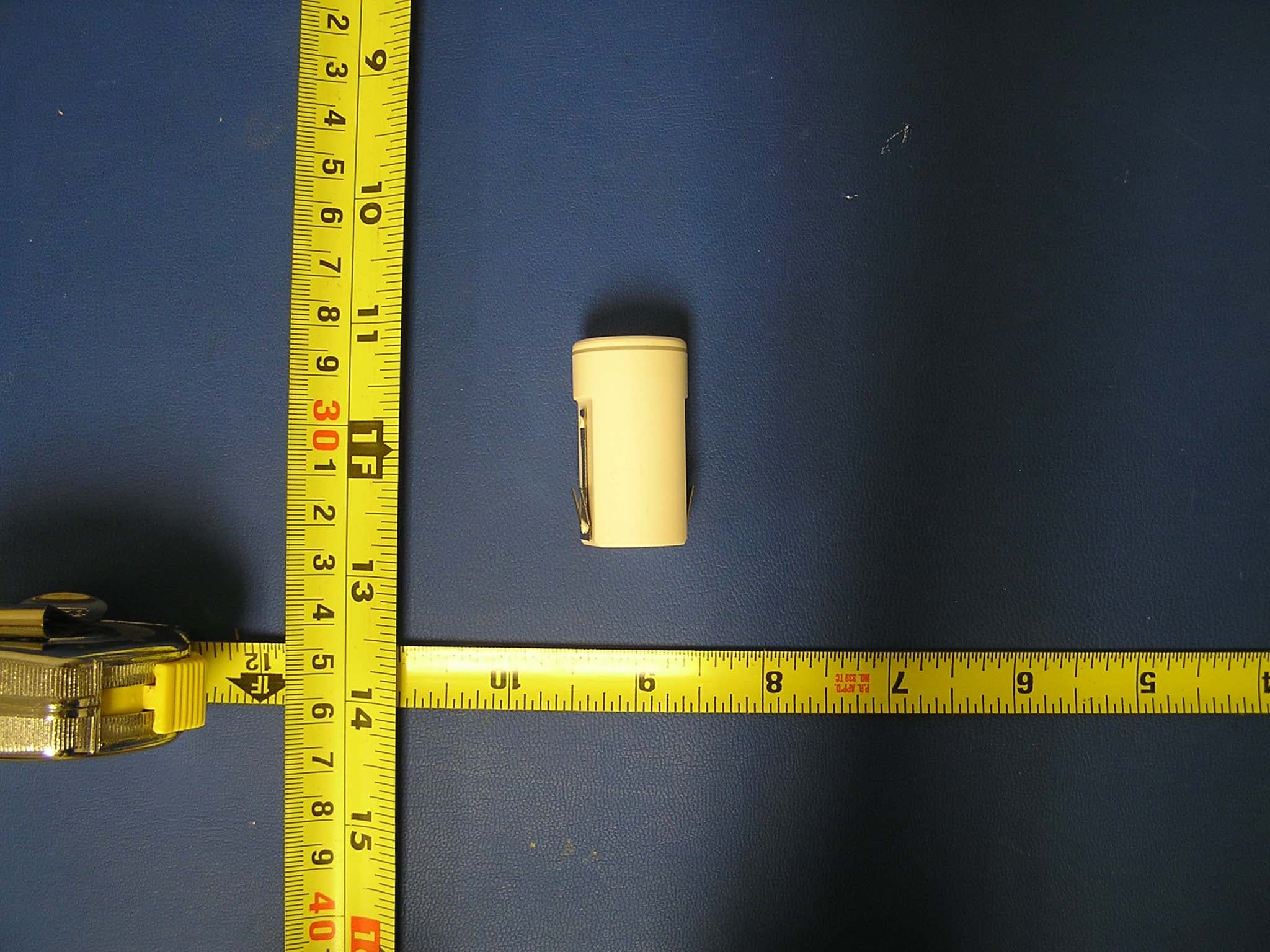
Click to zoom
Application Details
- Equipment Class
- DSC - Part 15 Security/Remote Control Transmitter
- Date of Grant
- Mar 20, 2008
- Application Purpose
- Original Equipment
- Date of Application
- Mar 20, 2008
- Equipment Note
- GE Recessed Door / Window Sensor
- Frequency Range
- 319.50800000 - 319.50800000
- Country
- United States
Documents & Files
Document Text
Text extracted from the exhibit documents filed with the FCC. Open a document above to read the original.
Users Manual
466-2316A • February 2008 Copyright © 2008 GE Security g DesignLine Recessed Door Contact Installation Instructions Introduction This is the GE DesignLine Recessed Door Contact Installation Instructions for model TX-1510-01-1. The TX-1510-01-1 is the industry’s most flexible supervised, recessed door contact allowing a multitude of applications while hiding the transmitter within a door frame. The contact uses a replaceable lithium battery and should last five years under normal usage. The contact comes with a standard flush-mount top and a flanged top. Unscrew the top to access the battery or change to a different top. Battery installation To install the battery, do the following: 1.Unscrew the top of the contact. 2.Carefully pull the circuit board out (Figure 1) of the contact. Before removing the circuit board, notice that it fits inside a channel on the inside of the case. Do not pull the circuit board unit by the antenna wire. Figure 1. Battery installation 3.Slide the battery onto the circuit board unit with the plus (+) side up. 4.Slide the circuit board unit into the contact. Make sure you slide it back into the channel guides for proper fit with the tamper switch facing up. 5.Screw the top back on the contact. When replacing batteries, use only Panasonic Lithium CR23 batteries for replacement. Mounting It is important to select the proper placement of the recessed transmitter and magnet. The transmitter has two separate tops that allow a flush mount or screw mount in case you accidently over drill the hole or require extra support to ensure the trans- mitter does not move. The magnet does not have a second flanged top so you must be careful to ensure that the magnet is tightly in place once installed. To mount the transmitter and magnet, do the following: 1.Install the CR2 battery if you have not already done so (Figure 1). 2.Select a location on the door frame for the TX-1510-01-1 transmitter and magnet to be installed (Figure 2). Use a marker to mark the placement and ensure that the two holes you intend to drill are lined up directly across from each other. Figure 2. Mounting Note: This is only one mounting option. You should select the best mounting method based on the application. 3.Using an 7/8 in. drill bit, slowly drill the first hole for the magnet. The TX-1510-01-1 was specifically designed to be slightly larger than an 7/8 in. hole so you will need to care- fully drill to fit by slowly routing the hole little by little to ensure a snug fit. 4.Using a 7/8 in. drill bit, drill the mating hole for the trans- mitter and use either the standard flush-mount cap and insert the transmitter for a snug fit, or use the flanged cap and use the screws provided to mount the transmitter to the door frame. CAUTION: You must be free of all static electricity before handling sensor circuit baords. Touch a grounded, bare metal surface before touching cirucuit boards or wear a grounding strap. WARNING: The battery may explode if mistreated. Do not recharge, disassemble, or dispose of in fire. Battery Antenna Circuit board Contact Tamper switch DesignLine Recessed Door Contact Installation Instructions 2 Enrolling The following section describes general guidelines for program- ming (learning) the sensor into the panel’s memory. Refer to you panel documentation for complete programming details. To program (learn) the contact into the panel, do the following: 1.Unscrew the top of the contact. 2.Set the panel into program mode. 3.Refer to your panel documentation for instructions for learning sensors. 4.Press and release the tamper switch on the top of the contact circuit board (Figure 1 on page 1)until the panel responds. 5.Replace the contact top. 6.Exit program mode. Specifications BatteryCR2032, 3 VDC, 225 mAh, Lithium Coin Cell Typical battery life5 to 8 years Transmitter frequency319.508 MHz (crystal-controlled) Transmitter frequency tolerance ± 8 kHz Bandwidth24 kHz Modulation typeAmplitude shift key (ASK) Unique ID codes16 million Peak field strengthTypical 35,000 uV/m at 3 m Supervisory interval64 minutes Operating temperature10 to 120°F (-12 to 49°C) EnclosurePC-540 Weight0.63 oz. (18 g) Dimensions (L x W x H)1.70 x 1.10 x 0.91 in. (4.32 x 2.76 x 2.32 cm) ColorBelgian gray FCCThis device complies with part 15 of the FCC rules. Operation is subject to the following conditions: 1. This device may not cause harmful interference. 2. This device must accept any interference received, including interference that may cause undesired operation. Changes or modifications not expressly approved by the party responsible for compliance could void the user’s authority to operate the equipment . FCC ID: B4Z-TX-1510-01 Industry Canada ID: 1175C-TX151001 EMCEuropean representative for manufacture (EMC): GE Security, Kelvinstraat 7, 6003 DH Weert , Nederland The European directive Waste Electrical and Electronic Equipment (WEEE) aims to minimize the impact of electrical and electronic equipment waste on the environment and human health. For proper treatment, recovery, and recycling, return the equipment marked with this symbol to your local supplier upon the purchase of equiva- lent new equipment , or dispose of it in designated collection points. For more information, visit www.recyclethis.com. Technical support Toll-free: 888.GESECURity (888.437.3287) in the US, including Alaska and Hawaii; Puerto Rico; Canada. Outside the toll-free area: Contact your local dealer. www.gesecurity.com
Cover Letter(s)
12/10/2007 Federal Communications Commission Equipment Authorization branch 7435 Oakland Mills Road Columbia, MD 21046 Re: Request for Confidentiality Gentlemen, In reference to the application under FCC ID: B4Z-TX-1510-01 and pursuant to Sections 0.457(d)(l)(ii) and 0.459 of the Commission’s Rules, the Applicant hereby requests confidential treatment of the accompanying information as outlined below: Schematics Block Diagrams Theory of Operation . These documents contain detailed system and equipment description and related information about the product that GE Security considers to be proprietary, confidential, and a custom design and, otherwise, would not release to the general public. Since this design is a basis from which future technological products will evolve, GE Security considers that this information would be of benefit to its competitors, and that disclosure of the information in these documents would give competitors an unfair advantage in the market. Sincerely, Rick Conner Regulatory Liaison GE Security Ph 651-779-4824 Fx 651-779-4884 [email protected]
Parts List/Tune Up Info
Antenna Specification TX-1510-01-1 Rev 1 The TX-1510-01-1 transmitter uses and internal -15 dBi wire loop antenna which is not replaceable by the user.
Test Report
FCC CFR47 PART 15 SUBPART C IC RSS-210 CERTIFICATION TEST REPORT FOR GE RECESSED DOOR / WINDOW SENSOR MODEL NUMBER: TX-1510-01-1 FCC ID: B4Z-TX-1510-01 IC: 1175C-TX151001 REPORT NUMBER: 07U11475-1 ISSUE DATE: NOVEMBER 27, 2007 Prepared for GE SECURITY 1275 RED FOX ROAD ARDEN HILLS, MN 55112, U.S.A. Prepared by COMPLIANCE CERTIFICATION SERVICES 47173 BENICIA STREET FREMONT, CA 94538, U.S.A. TEL: (510) 771-1000 FAX: (510) 661-0888 REPORT NO: 07U11475-1 DATE: NOVEMBER 27, 2007 EUT: GE RECESSED DOOR / WINDOW SENSOR FCC ID: B4Z-TX-1510-01 IC: 1175C-TX151001 Page 2 of 28 COMPLIANCE CERTIFICATION SERVICES DOCUMENT NO: CCSUP4031A 47173 BENICIA STREET, FREMONT, CA 94538, USA TEL: (510) 771-1000 FAX: (510) 661-0888 This report shall not be reproduced except in full, without the written approval of CCS. Revision History Rev. Issue Date Revisions Revised By -- 11/27/07 Initial Issue T. Chan REPORT NO: 07U11475-1 DATE: NOVEMBER 27, 2007 EUT: GE RECESSED DOOR / WINDOW SENSOR FCC ID: B4Z-TX-1510-01 IC: 1175C-TX151001 Page 3 of 28 COMPLIANCE CERTIFICATION SERVICES DOCUMENT NO: CCSUP4031A 47173 BENICIA STREET, FREMONT, CA 94538, USA TEL: (510) 771-1000 FAX: (510) 661-0888 This report shall not be reproduced except in full, without the written approval of CCS. TABLE OF CONTENTS 1. ATTESTATION OF TEST RESULTS.................................................................................... 4 2. TEST METHODOLOGY ........................................................................................................ 5 3. FACILITIES AND ACCREDITATION.................................................................................... 5 4. CALIBRATION AND UNCERTAINTY .................................................................................. 5 4.1. MEASURING INSTRUMENT CALIBRATION ................................................................ 5 4.2. MEASUREMENT UNCERTAINTY ................................................................................. 5 5. EQUIPMENT UNDER TEST ................................................................................................. 6 5.1. DESCRIPTION OF EUT ................................................................................................. 6 5.2. SOFTWARE AND FIRMWARE ...................................................................................... 6 5.3. WORST-CASE CONFIGURATION AND MODE............................................................ 6 5.4. DESCRIPTION OF AVAILABLE ANTENNAS ................................................................ 6 5.5. DESCRIPTION OF TEST SETUP .................................................................................. 7 6. TEST AND MEASUREMENT EQUIPMENT ......................................................................... 9 7. LIMITS AND RESULTS ...................................................................................................... 10 7.1. 20dB & 99% BANDWIDTHS ........................................................................................ 10 7.2. MAXIMUM MODULATION PERCENTAGE (M%) ........................................................ 13 7.3. LESS THAN 5 SECONDS PLOT ................................................................................. 18 7.4. RADIATED EMISSIONS .............................................................................................. 20 7.4.1. TRANSMITTER RADIATED SPURIOUS EMISSIONS ......................................... 20 7.4.2. RECEIVER SPURIOUS EMISSIONS LIMIT ......................................................... 25 8. SETUP PHOTOS................................................................................................................. 26 REPORT NO: 07U11475-1 DATE: NOVEMBER 27, 2007 EUT: GE RECESSED DOOR / WINDOW SENSOR FCC ID: B4Z-TX-1510-01 IC: 1175C-TX151001 Page 4 of 28 COMPLIANCE CERTIFICATION SERVICES DOCUMENT NO: CCSUP4031A 47173 BENICIA STREET, FREMONT, CA 94538, USA TEL: (510) 771-1000 FAX: (510) 661-0888 This report shall not be reproduced except in full, without the written approval of CCS. 1. ATTESTATION OF TEST RESULTS COMPANY NAME: GE SECURITY 1275 RED FOX ROAD ARDEN HILLS, MN 55112, U.S.A. EUT DESCRIPTION: GE RECESSED DOOR / WINDOW SENSOR MODEL: TX-1510-01-1 SERIAL NUMBER: 073161 DATE TESTED: NOVEMBER 26, 2007 APPLICABLE STANDARDS STANDARD TEST RESULTS FCC PART 15 SUBPART C NO NON-COMPLIANCE NOTED RSS-210 Issue 7 NO NON-COMPLIANCE NOTED Compliance Certification Services, Inc. tested the above equipment in accordance with the requirements set forth in the above standards. The test results show that the equipment tested is capable of demonstrating compliance with the requirements as documented in this report. Note: The results documented in this report apply only to the tested sample, under the conditions and modes of operation as described herein. This document may not be altered or revised in any way unless done so by Compliance Certification Services and all revisions are duly noted in the revisions section. Any alteration of this document not carried out by Compliance Certification Services will constitute fraud and shall nullify the document. No part of this report may be used to claim product certification, approval, or endorsement by NVLAP, NIST, or any government agency. Approved & Released For CCS By: Tested By: THU CHAN TOM CHEN EMC SUPERVISOR EMC ENGINEER COMPLIANCE CERTIFICATION SERVICES COMPLIANCE CERTIFICATION SERVICES REPORT NO: 07U11475-1 DATE: NOVEMBER 27, 2007 EUT: GE RECESSED DOOR / WINDOW SENSOR FCC ID: B4Z-TX-1510-01 IC: 1175C-TX151001 Page 5 of 28 COMPLIANCE CERTIFICATION SERVICES DOCUMENT NO: CCSUP4031A 47173 BENICIA STREET, FREMONT, CA 94538, USA TEL: (510) 771-1000 FAX: (510) 661-0888 This report shall not be reproduced except in full, without the written approval of CCS. 2. TEST METHODOLOGY The tests documented in this report were performed in accordance with ANSI C63.4-2003, FCC CFR 47 Part 2 and FCC CFR 47 Part 15, IC RSS-210 and IC RSS-212. 3. FACILITIES AND ACCREDITA…
Text truncated - open the document above for the full version.
Test Setup Photos
REPORT NO: 07U11475-1 DATE: NOVEMBER 27, 2007 EUT: GE RECESSED DOOR / WINDOW SENSOR FCC ID: B4Z-TX-1510-01 IC: 1175C-TX151001 Page 26 of 28 COMPLIANCE CERTIFICATION SERVICES DOCUMENT NO: CCSUP4031A 47173 BENICIA STREET, FREMONT, CA 94538, USA TEL: (510) 771-1000 FAX: (510) 661-0888 This report shall not be reproduced except in full, without the written approval of CCS. 8. SETUP PHOTOS RADIATED RF MEASUREMENT SETUP FOR PORTABLE CONFIGURATION X-AXIS PHOTO REPORT NO: 07U11475-1 DATE: NOVEMBER 27, 2007 EUT: GE RECESSED DOOR / WINDOW SENSOR FCC ID: B4Z-TX-1510-01 IC: 1175C-TX151001 Page 27 of 28 COMPLIANCE CERTIFICATION SERVICES DOCUMENT NO: CCSUP4031A 47173 BENICIA STREET, FREMONT, CA 94538, USA TEL: (510) 771-1000 FAX: (510) 661-0888 This report shall not be reproduced except in full, without the written approval of CCS. Y-AXIS PHOTO REPORT NO: 07U11475-1 DATE: NOVEMBER 27, 2007 EUT: GE RECESSED DOOR / WINDOW SENSOR FCC ID: B4Z-TX-1510-01 IC: 1175C-TX151001 Page 28 of 28 COMPLIANCE CERTIFICATION SERVICES DOCUMENT NO: CCSUP4031A 47173 BENICIA STREET, FREMONT, CA 94538, USA TEL: (510) 771-1000 FAX: (510) 661-0888 This report shall not be reproduced except in full, without the written approval of CCS. END OF REPORT Z-AXIS PHOTO
Contact Information
Applicant
Konstantin Khrustov(Compliance Leader)
Test Firm
Compliance Certification ServicesBarbara Judge
Technical Specifications
| # | Rule Parts | Frequency Range | Power Output |
|---|---|---|---|
| 1 | 15.231 | 319.508 MHz - 319.508 MHz | - |
Other Applications from UTC Fire & Security Americas Corporation, Inc.

B4Z-944-3G
May 04, 2015AV-3G
Equipment Class
PCB - PCS Licensed Transmitter
B4Z-962-BT
May 04, 2015AVO-BT
Equipment Class
DSS - Part 15 Spread Spectrum Transmitter
B4Z-959-ZW
Apr 29, 2015AVO-ZW
Equipment Class
DXT - Part 15 Low Power Transceiver, Rx Verified
B4Z-958-BTWI
Apr 29, 2015AVO-BTWIFI
Equipment Class
DTS - Digital Transmission System
B4Z-680F-PIR
Dec 01, 2014PIR Security System Transmitter
Equipment Class
DSC - Part 15 Security/Remote Control Transmitter