B4ZCGGAA3Motion Detector
UTC Fire & Security Americas Corporation, Inc.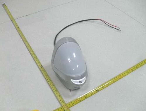
Click to zoom
Application Details
- Equipment Class
- FDS - Part 15 Field Disturbance Sensor
- Date of Grant
- Oct 31, 2012
- Application Purpose
- Original Equipment
- Date of Application
- Oct 29, 2012
- Equipment Note
- Motion Detector
- Frequency Range
- 10532.00000000 - 10532.00000000
- Country
- United States
Documents & Files
Document Text
Text extracted from the exhibit documents filed with the FCC. Open a document above to read the original.
Users Manual
© 2012 UTC Fire & Security. All rights reserved. 1 / 8 P/N 1069154U-F1 • REV 4.0 • ISS 05OCT12 DDI602U-F1 Outdoor Dual PIR Detector Installation Sheet EN 1 2 3 4 5 6 2 / 8 P/N 1069154U-F1 • REV 4.0 • ISS 05OCT12 7 8 9 10 11 12 13 P/N 1069154U-F1 • REV 4.0 • ISS 05OCT12 3 / 8 14 15 16 EN: Installation Sheet Package The package contains: • 1 x DDI602U-F1 • 1 x drilling template for fixing holes • 2 x 31.75 mm / 1.25 in. wall plugs • 2 x 31.75 mm / 1.25 in. screws • 1 x lens mask • 2 x additional curtain shutters • 1 x tamper cup • 2 x tamper caps (different lengths) • 1 x plastic locking tool • 1 x installation sheet • 1 x front cover screw cap Introduction The DDI602 Outdoor Dual PIR Detector is an outdoor motion detector and alarm trigger that uses two independent passive infrared detectors plus a microwave sensor module. All three sensors must trigger to cause the detector to signal an alarm. The DDI602U-F1 uses triple detection technology to deliver precise, reliable presence detection. It is designed for use in CCTV and intruder alarm systems. Programmable options include a variable pulse count and a choice of three detection ranges: 10 m / 33 ft., 18 m / 59 ft., and 25 m / 82 ft. The integral dual-axis tilt sensor allows 180° of pan and 90° of tilt. This increases the speed of the outdoor installation and provides incredibly accurate aiming of the detection pattern. The electronics module is acrylic coated for additional component stability. It is encased in a vandal-resistant, high- impact, UV stabilized plastic housing with an opaque polyethylene front cover ensuring that the sensor is impervious to and unaffected by weather conditions. The combination of precision electronics, digital white light filtering, and double shielding eliminates false alarms from the sun and other visible light sources. The DDI602U-F1 design has a neat and professional appearance that gives no visible indication of the orientation of the detector head and totally hides the wiring. Quick installation 1. Mount and connect the detector following the instructions given later in this sheet. 2. Apply supply voltage to the unit. The detection LED (blue) flashes three times. 3. Wait approximately 2 to 3 minutes to allow the detector to settle. 4. Press the programming button once to activate walk test mode. The detection LED is now enabled for five minutes. Note: The front cover must be fitted when walk testing. The default settings are: • Range: 25 meters / 82 feet • Pulse count: 1 • Detection LED: off 4 / 8 P/N 1069154U-F1 • REV 4.0 • ISS 05OCT12 Mounting the unit During installation, protect the electronics against water, as trapped moisture can affect or damage the unit. To mount the detector: 1. Drill the wall to accept the two fixing screws, the cable entry, and the tamper cup (if used). See Figures 1 and 3. A hole-drilling template is provided. Notes • Leave a minimum 10 cm (4 inches) clearance above the top of the detector housing to allow the cover and the detector to be positioned correctly. • We recommend using the tamper cup on uneven wall surfaces. • When mounting the units side by side, a minimum space of 1 m must be left between the detectors and the detectors must not be looking directly towards each other. No minimum space is required when mounting the units back to back. • The recommended optimum mounting height for the detector is 3 m. Whilst it is possible to mount the unit higher, this will give a reduced detection range and will require the detection subject to move further through the already reduced detection area before an activation is signalled. 2. Remove the cover assembly by loosening the locking screw. Squeeze the sides of the front cover to release the internal catches. The cover hinges from the top and lifts out of the location slot. See Figure 2. 3. Use a razor knife to open a rubber seal to allow the cabling into the unit (see Figure 4). Feed standard eight- core alarm cable into the cable entry. Bare the wires and connect to the top PCB terminal block (Figure 5, item 2). 4. Screw the unit to the wall ensuring that the tamper pin is correctly located and that the tamper microswitch is closed. To aid installation, two spare tamper feet are provided. One is 1 mm shorter and the other is 1 mm longer than the tamper foot originally fitted. The tamper foot is a push fit and can be removed by carefully pulling it from the pin. See Figure 1. 5. When the detector is aligned, connected, and programmed to suit the installation: a. Fit the cover to the detector base. b. Lightly screw the locking screw. c. Put the top of the locking tool into the small notch on each side of the cover, and then apply slight pressure until the cover locks into the base, as shown in Figure 15. d. Tighten the locking screw. Connecting the unit The DDI602U-F1 includes jumpers that let you configure internal end-of-line (EOL) resistor values, when EOL resistors are required. Values are: 1, 2.2, 3.3, 4.7, 5.6, and 6.8 kΩ. Figure 5 shows: 1. EOL resistor jumpers 2. Wiring points Alternatively, you can remove the jumpers and connect a discrete resistor directly to the alarm or tamper outputs, as specified by third-party equipment. Table 1: Connections Terminal Label Description 1, 2 ALARM N/C Alarm relay, normally closed 2, 3 EOL End-of-line resistors 3, 4 TAMPER N/C Tamper relay, normally closed 5, 6 ALARM N/O Alarm relay, normally open 7, 8 +, − 12V DC 12 V power supply Multibeam alignment and masking The multifunction lens fitted to the DDI602U-F1 detector produces seven long-range beams and seven medium- to short-range curtain PIR beams. The PIR circuitry detects changes in heat and movement in the beam pattern; therefore items such as trees, shrubs, ponds, boiler flues, and animals should be considered when positioning the detector. The microwave module detects actual movement towards or away from the detector and is programmed to ignore any objects that move outside of the preselected detection range. Note: P…
Text truncated - open the document above for the full version.
Cover Letter(s)
1(1) Attention: Application Examiner Re: Request for confidentiality Applicant: UTC Fire and Security IC: 1175C-GJDMOTION To whom it may concern, Request is hereby submitted by UTC Fire and Security to withhold permanently from public review certain portions of this application for equipment certification. This request for confidentiality is made pursuant to the Canadian Access to Information Act. In particular, the following sections of the application are to be kept permanently confidential: [Select one or more of items below, as appropriate] • Schematics • Detailed Block diagrams • Detailed Operational/Functional Description • Parts list Rationale for request for confidentiality: UTC Fire and Security has invested considerable time and materials in research and development to produce the referenced product. Disclosure of the confidential portions of this application to competitors would not only give them significant competitive advantages in developing similar products, but would also disclose successful implementation of unpublished, leading edge technology developed by us. Sincerely, Rick Conner UTC Fire & Security Americas Corporation, Inc. Senior Compliance Specialist 1275 Red Fox Road Arden Hills, MN 55112 Ph 651-779-4824 Fx 651-779-4884 [email protected]
Cover Letter(s)
1(1) 10/31/2012 Attention: Application Examiner Re: Request for confidentiality Applicant: UTC Fire & Security FCC ID: B4Z-CGGAA3 To whom it may concern, Permanent Confidentiality Request is hereby submitted by UTC Fire & Security to withhold permanently from public review certain portions of the application for equipment certification for the referenced FCC identifiers. This request for confidentiality is made pursuant to 47 CFR 0.457(d) and 0.459 of the FCC Rules. In particular, the following sections of the application are to be kept permanently confidential: • Schematics • Detailed Block diagrams • Detailed Operational/Functional Description • Parts list Rationale for request for confidentiality: UTC Fire & Security has invested considerable time and materials in research and development to produce the referenced product. Disclosure of the permanently confidential portions of this application to competitors would not only give them significant competitive advantages in developing similar products, but would also disclose successful implementation of unpublished, leading edge technology developed by us. If you have questions or need further information, please contact the undersigned. Rick Conner UTC Fire & Security Americas Corporation, Inc. Senior Compliance Specialist 1275 Red Fox Road Arden Hills, MN 55112 Ph 651-779-4824 Fx 651-779-4884 [email protected]
ID Label/Location Info
Label-Label Placement
ID Label/Location Info
Label/Label Placement
Test Report
This report is for the exclusive use of Intertek's Client and is provided pursuant to the agreement between Intertek and its Client. Intertek's responsibility and liability are limited to the terms and conditions of the agreement. Intertek assumes no liability to any party, other than to the Client in accordance with the agreement, for any loss, expense or damage occasioned by the use of this report. Only the Client is authorized to permit copying or distribution of this report and then only in its entirety. Any use of the Intertek name or one of its marks for the sale or advertisement of the tested material, product or service must first be approved in writing by Intertek. The observations and test results in this report are relevant only to the sample tested. This report by itself does not imply that the material, product, or service is or has ever been under an Intertek certification program. Non-Specific EMC Report Shell Rev. August 2012 Page 1 of 33 EMISSIONS TEST REPORT Report Number: 100869972BOX-001 Project Number: G100869972 Report Issue Date: 9/27/2012 Product Designation: DDI602U-F1 Standards: CFR47 FCC Part 15 Subpart C 15.245:2012 IC RSS-210 Issue 8 December 2010 Annex 7 IC RSS-Gen Issue 3 December 2010+Notice DRS 2012-DRS0126 CFR47 FCC Part 15 Subpart B:2012 IC ICES-003 Issue 5 August 2012 Tested by: Client: Intertek Testing Services NA, Inc. 70 Codman Hill Road Boxborough, MA 01719 UTC Fire and Security 9 Farm Springs Road Farmington, CT 06034 Report prepared by Reviewer Report reviewed by Vathana Ven / Senior Project Engineer Nicholas Abbondante / Transmitter Staff Engineer Intertek Report Number: 100869972BOX-001 Issued: 09/27/2012 Non-Specific EMC Report Shell Rev. August 2012 Page 2 of 33 1 Introduction and Conclusion The tests indicated in section 2.0 were performed on the product constructed as described in section 4.0. The remaining test sections are the verbatim text from the actual data sheets used during the investigation. These test sections include the test name, the specified test Method, a list of the actual Test Equipment Used, documentation Photos, Results and raw Data. No additions, deviations, or exclusions have been made from the standard(s) unless specifically noted. Based on the results of our investigation, we have concluded the product tested complies with the requirements of the standard(s) indicated. The results obtained in this test report pertain only to the item(s) tested. 2 Test Summary Section Test full name Result 3 Client Information 4 Description of Equipment Under Test 5 System Setup and Method 6 Fundamental Field Strength (CFR47 FCC Part 15 Subpart C:2012,15.245; IC RSS-210 Issue 8 December 2010 Annex 7) Pass 7 Radiated Emissions CFR47 FCC Part 15 Subpart C:2012, 15.209 and 15.245; IC RSS-210 Issue 8 December 2010 Annex 7, CFR47 FCC Part 15 Subpart B:2012, IC ICES-003 Issue 5 August 2012) Pass 8 20 dB Bandwidth ( FCC PART 15C: 15.215(C), IC RSS-Gen Issue 3 December 2010 4.6.3) Pass 9 Revision History Intertek Report Number: 100869972BOX-001 Issued: 09/27/2012 Non-Specific EMC Report Shell Rev. August 2012 Page 3 of 33 3 Client Information This EUT was tested at the request of: Company: UTC Fire and Security 9 Farm Springs Road Farmington, CT 06034 Contact: Rick Conner Telephone: (651) 779-4824 Fax: (651) 779-4884 Email: [email protected] 4 Description of Equipment Under Test Equipment Under Test Description Manufacturer Model Number Serial Number Outdoor motion sensors UTC Fire & Security DDI602U-F1 BOX1208291217-001 (Intertek assigned) (transmit) Outdoor motion sensors UTC Fire & Security DDI602U-F1 BOX1208291217-003 (Intertek assigned) (Normal mode) Receive Date: 08/29/2012 Received Condition: Good Type: Production Description of Equipment Under Test (provided by client) The EUT is an Outdoor motion sensor. Equipment Under Test Power Configuration Rated Voltage Rated Current Rated Frequency Number of Phases 12VDC 11mA N/A N/A Operating modes of the EUT: No. Descriptions of EUT Exercising 1 For transmitter testing, the sample was programmed to transmit with a 100% duty cycle. 2 For occupied bandwidth testing, the sample with normal mode was used. Intertek Report Number: 100869972BOX-001 Issued: 09/27/2012 Non-Specific EMC Report Shell Rev. August 2012 Page 4 of 33 5 System Setup and Method Cables ID Description Length (m) Shielding Ferrites Termination 1 Wires <3 None None DC supply Support Equipment Description Manufacturer Model Number Serial Number DC power supply Electro Industries DIGI35A M12/EM 1127-01 5.1 Method: Configuration as required by ANSI C63.4:2009. 5.2 EUT Block Diagram: Intertek Report Number: 100869972BOX-001 Issued: 09/27/2012 Non-Specific EMC Report Shell Rev. August 2012 Page 5 of 33 6 Fundamental Field Strength 6.1 Method Tests are performed in accordance with CFR47 FCC Part 15 Subpart C:2012,15.245, IC RSS-210 Issue 8 December 2010 Annex 7 and ANSI C63.4:2009. TEST SITE: 10m ALSE The 10m ALSE is 13m (Length) x 21m (Depth) x 10m (Height) with the effective size in terms of space from the tips of the absorber is 12m (Length) x 20m (Depth) x 8.5m (Height). This chamber achieves broadband performance using a unique arrangement of hybrid and ferrite tile absorber. This chamber has a built in 3m diameter turntable (Embedded type). The metal structure of the table makes electrical connection around the entire circumference of the turntable to the ground plane with a metal brush type connection. The turntable is located on one end of the chamber and the antennas are mounted 3 and 10 meters away at the other end of the chamber on the adjustable an Antenna Mast. The antenna mast is a non-conductive bore sighted type with remote control of antenna height and polarization. The Antenna Mast and the turntable can be remotely controlled through the controller located in the adjacent Control room. A wooden table 80 cm high is used for table-top equipment. Measurement Uncertainty For radiated emissions, lab U(3.5 dB at 3m and…
Text truncated - open the document above for the full version.
Test Setup Photos
Intertek Report Number: 100869972BOX-001 Issued: 09/27/2012 Non-Specific EMC Report Shell Rev. August 2012 Page 8 of 33 6.4 Setup Photographs:
Contact Information
Applicant
Konstantin Khrustov(Compliance Leader)
Test Firm
Intertek Testing Services NA Inc.Yaqing Liu
[email protected]978 635 8662
Technical Specifications
| # | Rule Parts | Frequency Range | Power Output |
|---|---|---|---|
| 1 | 15.245 | 10.53 GHz - 10.53 GHz | - |
Other Applications from UTC Fire & Security Americas Corporation, Inc.

B4Z-944-3G
May 04, 2015AV-3G
Equipment Class
PCB - PCS Licensed Transmitter
B4Z-962-BT
May 04, 2015AVO-BT
Equipment Class
DSS - Part 15 Spread Spectrum Transmitter
B4Z-959-ZW
Apr 29, 2015AVO-ZW
Equipment Class
DXT - Part 15 Low Power Transceiver, Rx Verified
B4Z-958-BTWI
Apr 29, 2015AVO-BTWIFI
Equipment Class
DTS - Digital Transmission System
B4Z-680F-PIR
Dec 01, 2014PIR Security System Transmitter
Equipment Class
DSC - Part 15 Security/Remote Control Transmitter