B7MTR-6000TISE-WBTIS Transmitter for HAR/Homeland Security Broadcasting
Information Station Specialists, Inc.
Click to zoom
Application Details
- Equipment Class
- TNB - Licensed Non-Broadcast Station Transmitter
- Date of Grant
- Mar 22, 2010
- Application Purpose
- Original Equipment
- Date of Application
- Sep 14, 2009
- Equipment Note
- TIS Transmitter for HAR/Homeland Security Broadcasting
- Frequency Range
- 0.53000000 - 1.71000000
- Country
- United States
Documents & Files
Document Text
Text extracted from the exhibit documents filed with the FCC. Open a document above to read the original.
Users Manual
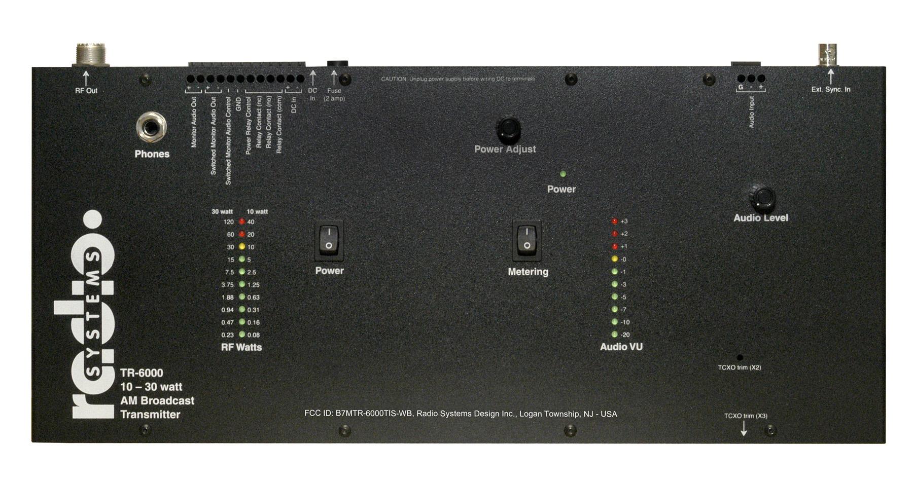
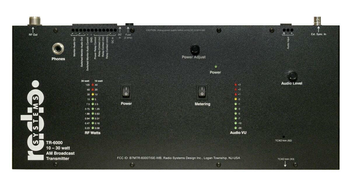
Radio Systems, Inc.TR-6000 Manual 4/01Page 1 TR-6000 10 Watt AM Broadcast Transmitter Manual Radio Systems, Inc.TR-6000 Manual 4/01Page 2 Table Of Contents Operating Instructions..........................................................................................................3 Overview.....................................................................................................................................3 Available Options........................................................................................................................3 Front Panel Controls....................................................................................................................3 Connections.................................................................................................................................3 TR-6000 Jumper Settings......................................................................................................4 TR-6000 Frequency Change Procedure.................................................................................6 TR-6000 Test Procedure.......................................................................................................7 Test Point and Calibration Location Illustrations................................................................10 Frequency Programming Chart...........................................................................................12 Bill of Materials..................................................................................................................16 Schematic...........................................................................................................................17 Warranty.............................................................................................................................18 Repair Policy.......................................................................................................................32 Return Instructions.............................................................................................................32 Radio Systems, Inc.TR-6000 Manual 4/01Page 3 TR-6000 AM Broadcast Transmitter Operating Instructions Overview The TR-6000 is a solid-state, class D AM transmitter specially designed for traveler’s information, carrier current, roadside radio, and other low-power broadcast band AM applications. The unit features a frequency synthesized oscillator, full remote control, LED power and audio meters, 0 to 10 watt output power, short circuit protections, balanced audio inputs, and monitor and headphone outputs. The TR-6000 is shipped factory set for 10-watt operation. 10-watt units are provided with a 24-volt external power supply. The TR-6000 can be powered by storage batteries (not supplied). The TR-6000 is FCC certified for TIS operation anywhere within the AM broadcast band. Available Options • brackets for wall or 19’ EIA rack mounting • super stable crystal option @ 1.5 ppm • ultra stable crystal option Front Panel Controls Power switch - supplies DC to the unit Do not power up without a 50 ohm output load. Meter switch - illuminates power and VU LED meters. Leave off to increase efficiency for battery or solar operation. Power Adjust - sets RF output level Set (with no modulation required) to desired carrier level on 10 watt scale Mod(ulation) adjust - set for 100% modulation on VU meter For TIS operation the internal audio filter must be engaged. Consult the internal parts layout diagram for location. Connections CAUTION: Make all connectors prior to applying DC voltage via the supplied transformer or any external DC source. RF out - Connect to 50 ohm load Audio input - Apply line-level balanced audio source DC in - Apply 24 volts to 24 volt terminals via DC transformer connect or DC input screw terminals (do not apply both inputs simultaneously, however DC may be derived from the DC terminals for low-current applications when the transformer is utilized). Relay contacts - (Depending on internal strap programming) This relay can control or be controlled by the transmitter for external device remote control. Switched monitor audio control - controls the audio output feed to a remote location for remote monitoring. Switched monitor audio out - balanced/switched (see above) monitor feed. Monitor audio out - balanced/non-switched audio feed. Radio Systems, Inc.TR-6000 Manual 4/01Page 4 TR-6000 Jumper Settings J3Power Control Relay Configuration - Relay power supplied by main + input (fused) - Relay power supplied by N.O. contact - Relay power supplied by common contact - Relay power supplied by N.C. contact - Relay power supplied by main + input (unfused) J5TIS audio filter enable TIS filter disabled TIS filter enabled J6VU meter display mode Install jumper for bar mode bar mode Leave open for dot mode dot mode J7Power LED to follow metering switch Power LED independent of metering Power LED follows metering J9Standard oscillator disable Jump to disable the standard oscillator Enable the standard oscillator J12Power meter display mode Jump for bar mode Open for dot mode J15Relay Supply Voltage 24V SupplyNote: Jumper representations on this page are orientated to match circuit board silk screens. 48V Supply * * * * * * * Note: * Indicates Factory Setting Radio Systems, Inc.TR-6000 Manual 4/01Page 5 J8Clock Source J10Reference I/OJ11 Standard OscillatorNo I/O TCXONo I/O Standard OscillatorStandard Oscillator Out TCXOTCXO Out External Reference InExternal Reference In Note: * Indicates Factory Setting * ** Radio Systems, Inc.TR-6000 Manual 4/01Page 6 TR-6000 Frequency Change Procedure 1. Set dip switches S1, S2 and S3 for the desired output frequency. 2. Set the output filter jumpers for low or high band. 3. Adjust the power control VR1 to its minimum position. 4. Turn VR10 and VR11 fully counter clockwise. 5. Apply power to the unit. 6. Measure the oscillator frequency at U11 pin 13. 7. Adjust C57 for an os…
Text truncated - open the document above for the full version.
Operational Description
Radio Systems, Inc.TR-6000 Manual 4/01Page 1 TR-6000 10 Watt AM Broadcast Transmitter Manual Radio Systems, Inc.TR-6000 Manual 4/01Page 2 Table Of Contents Operating Instructions..........................................................................................................3 Overview.....................................................................................................................................3 Available Options........................................................................................................................3 Front Panel Controls....................................................................................................................3 Connections.................................................................................................................................3 TR-6000 Jumper Settings......................................................................................................4 TR-6000 Frequency Change Procedure.................................................................................6 TR-6000 Test Procedure.......................................................................................................7 Test Point and Calibration Location Illustrations................................................................10 Frequency Programming Chart...........................................................................................12 Bill of Materials..................................................................................................................16 Schematic...........................................................................................................................17 Warranty.............................................................................................................................18 Repair Policy.......................................................................................................................32 Return Instructions.............................................................................................................32 Radio Systems, Inc.TR-6000 Manual 4/01Page 3 TR-6000 AM Broadcast Transmitter Operating Instructions Overview The TR-6000 is a solid-state, class D AM transmitter specially designed for traveler’s information, carrier current, roadside radio, and other low-power broadcast band AM applications. The unit features a frequency synthesized oscillator, full remote control, LED power and audio meters, 0 to 10 watt output power, short circuit protections, balanced audio inputs, and monitor and headphone outputs. The TR-6000 is shipped factory set for 10-watt operation. 10-watt units are provided with a 24-volt external power supply. The TR-6000 can be powered by storage batteries (not supplied). The TR-6000 is FCC certified for TIS operation anywhere within the AM broadcast band. Available Options • brackets for wall or 19’ EIA rack mounting • super stable crystal option @ 1.5 ppm • ultra stable crystal option Front Panel Controls Power switch - supplies DC to the unit Do not power up without a 50 ohm output load. Meter switch - illuminates power and VU LED meters. Leave off to increase efficiency for battery or solar operation. Power Adjust - sets RF output level Set (with no modulation required) to desired carrier level on 10 watt scale Mod(ulation) adjust - set for 100% modulation on VU meter For TIS operation the internal audio filter must be engaged. Consult the internal parts layout diagram for location. Connections CAUTION: Make all connectors prior to applying DC voltage via the supplied transformer or any external DC source. RF out - Connect to 50 ohm load Audio input - Apply line-level balanced audio source DC in - Apply 24 volts to 24 volt terminals via DC transformer connect or DC input screw terminals (do not apply both inputs simultaneously, however DC may be derived from the DC terminals for low-current applications when the transformer is utilized). Relay contacts - (Depending on internal strap programming) This relay can control or be controlled by the transmitter for external device remote control. Switched monitor audio control - controls the audio output feed to a remote location for remote monitoring. Switched monitor audio out - balanced/switched (see above) monitor feed. Monitor audio out - balanced/non-switched audio feed. Radio Systems, Inc.TR-6000 Manual 4/01Page 4 TR-6000 Jumper Settings J3Power Control Relay Configuration - Relay power supplied by main + input (fused) - Relay power supplied by N.O. contact - Relay power supplied by common contact - Relay power supplied by N.C. contact - Relay power supplied by main + input (unfused) J5TIS audio filter enable TIS filter disabled TIS filter enabled J6VU meter display mode Install jumper for bar mode bar mode Leave open for dot mode dot mode J7Power LED to follow metering switch Power LED independent of metering Power LED follows metering J9Standard oscillator disable Jump to disable the standard oscillator Enable the standard oscillator J12Power meter display mode Jump for bar mode Open for dot mode J15Relay Supply Voltage 24V SupplyNote: Jumper representations on this page are orientated to match circuit board silk screens. 48V Supply * * * * * * * Note: * Indicates Factory Setting Radio Systems, Inc.TR-6000 Manual 4/01Page 5 J8Clock Source J10Reference I/OJ11 Standard OscillatorNo I/O TCXONo I/O Standard OscillatorStandard Oscillator Out TCXOTCXO Out External Reference InExternal Reference In Note: * Indicates Factory Setting * ** Radio Systems, Inc.TR-6000 Manual 4/01Page 6 TR-6000 Frequency Change Procedure 1. Set dip switches S1, S2 and S3 for the desired output frequency. 2. Set the output filter jumpers for low or high band. 3. Adjust the power control VR1 to its minimum position. 4. Turn VR10 and VR11 fully counter clockwise. 5. Apply power to the unit. 6. Measure the oscillator frequency at U11 pin 13. 7. Adjust C57 for an os…
Text truncated - open the document above for the full version.
Parts List/Tune Up Info
Oct 5, 2009 - 10:08am Radio Systems, Inc. Page 1 I N D E N T E D B I L L O F M A T E R I A L Items: TR-6000TIS Thru TR-6000TIS All Locations Selected Activity Codes: Active Items Only 11 Levels With No Blow Through No Selection On Basis Of Effectivity Date No Selection On Basis Of Obsolete Date Including: Reference Designators Level Seq Component-Item Component-Description Opr UOM Scrap Act Stk B/I Qty On-Hand Qty-Per-Parent Loc LLC Draw REV P/M Ctl B/F Qty-Allocated Qty-On-Order ==================================================================================================================================== Parent Item: TR-6000TIS RS TR-6000 AM TRANSMITTER TIS Loc: NJ LLC: 0 1 10 11719 TR-6000 BD ASSY VERSION 2V 0 EA .0 A Y N 1.000000 NJ 1 M Y N 2 10 11194 TRIMMER CAP 250-800PF 0 EA .0 A Y N 1.000000 SPRAGUE GME-50601,RF PART 305M NJ 2 P Y N Obsolete Date: 010110 2 20 11199 IC MIC4423YN 0 EA .0 A Y N 1.000000 MICREL MIC4423YN NJ 2 P Y N Obsolete Date: 010110 2 30 11200 IC MIC4424YN 0 EA .0 A Y N 1.000000 MICREL MIC4424YN NJ 2 P Y N Obsolete Date: 010110 2 40 11201 IC SA577 0 EA .0 A Y N 1.000000 PHILIPS SA577D NJ 2 P Y N Obsolete Date: 010110 2 50 11213 COIL 24 TURN 0 EA .0 A Y N 4.000000 NJ 2 M Y N Obsolete Date: 010110 3 10 11115 CORE T50-26B 0 EA .0 A Y N 4.000000 NJ 3 P Y N 3 20 11608 WIRE 28GA TEFLON SOLID ORANGE 0 FT .0 A N N 104.000000 NJ 3 P N N 2 60 11214 COIL 17 TURN 0 EA .0 A Y N 1.000000 NJ 2 M Y N Obsolete Date: 010110 3 10 11115 CORE T50-26B 0 EA .0 A Y N 1.000000 NJ 3 P Y N 3 20 11621 WIRE 28GA TEFLON SOLID VIOLET 0 FT .0 A N N 19.000000 NJ 3 P N N 2 70 11215 COIL 23 TURN 0 EA .0 A Y N 1.000000 NJ 2 M Y N Obsolete Date: 010110 Oct 5, 2009 - 10:08am Radio Systems, Inc. Page 2 I N D E N T E D B I L L O F M A T E R I A L Level Seq Component-Item Component-Description Opr UOM Scrap Act Stk B/I Qty On-Hand Qty-Per-Parent Loc LLC Draw REV P/M Ctl B/F Qty-Allocated Qty-On-Order ==================================================================================================================================== 3 10 11115 CORE T50-26B 0 EA .0 A Y N 1.000000 NJ 3 P Y N 3 20 11273 MAGNET WIRE 22 GA 0 FT .0 A N N 30.000000 NJ 3 P N N 2 80 11216 COIL 29/31 TURN CT 0 EA .0 A Y N 1.000000 NJ 2 M Y N Obsolete Date: 010110 3 10 10989 CORE T184-2 0 EA .0 A Y N 1.000000 MICROMETALS T184-2 NJ 3 P Y N 3 20 11454 WIRE 26GA TEFLON SOLID GREEN 0 FT .0 A N N 65.000000 NJ 3 P N N 3 30 11622 WIRE 26GA TEFLON SOLID YELLOW 0 FT .0 A N N 64.000000 NJ 3 P N N 2 90 11217 TRANSFORMER 6/4 TURN CT 0 EA .0 A Y N 1.000000 NJ 2 M Y N Obsolete Date: 010110 3 10 10990 CORE CMD5005 0 EA .0 A Y N 1.000000 NJ 3 P Y N 3 20 11754 WIRE 24 GA TEFLON SOLID BLACK 0 FT .0 A N N 10.000000 NJ 3 P N N 3 30 11755 WIRE 24 GA TEFLON SOLID RED 0 FT .0 A N N 8.000000 NJ 3 P Y N 2 100 11712 COIL 35T MULTI-TAP 0 EA .0 A Y N 2.000000 NJ 2 M Y N Obsolete Date: 010110 3 10 11714 CORE .250 ID X .750 OD 0 EA .0 A Y N 2.000000 MICROMETALS T72-2 NJ 3 P Y N 3 20 10106 MAGNET WIRE 28 GA. 0 IN .0 A N N 70.000000 BELDEN 8054 (1/2 LB SPOOL) NJ 3 P Y N 2 110 11713 COIL 36T MULTI-TAP 0 EA .0 A Y N 1.000000 NJ 2 M Y N Obsolete Date: 010110 3 10 11714 CORE .250 ID X .750 OD 0 EA .0 A Y N 1.000000 MICROMETALS T72-2 NJ 3 P Y N Oct 5, 2009 - 10:08am Radio Systems, Inc. Page 3 I N D E N T E D B I L L O F M A T E R I A L Level Seq Component-Item Component-Description Opr UOM Scrap Act Stk B/I Qty On-Hand Qty-Per-Parent Loc LLC Draw REV P/M Ctl B/F Qty-Allocated Qty-On-Order ==================================================================================================================================== 3 20 10106 MAGNET WIRE 28 GA. 0 IN .0 A N N 35.000000 BELDEN 8054 (1/2 LB SPOOL) NJ 3 P Y N 2 120 11790 TR-6000 VENDOR SUPPLIED ASSY 0 EA .0 A Y N 1.000000 NJ 2 P Y N Obsolete Date: 010110 2 130 2840 CHOKE 8 TURN 0 EA .0 A Y N 1.000000 NJ 2 M Y N Obsolete Date: 010110 3 10 4681 CORE .5 X .250 X .375 0 EA .0 A Y N 1.000000 T502537T MATL:CN20 NJ 3 P Y N 3 20 2934 WIRE 22GA TEFLON SOLID WHITE 0 FT .0 A N N 12.000000 NJ 3 P Y N 2 140 3931 POT 10K VERTICAL SINGLE 0 EA .0 A Y N 2.000000 PIHER PT15WV18-103A202011CA NJ 4 P Y N Obsolete Date: 010110 2 160 11120 IC Q2240I-1N 0 EA .0 A Y N 1.000000 NJ 2 P Y N Ref: U12 2 170 15858 HEADER 3 PIN PLUG TERMINAL 0 EA .0 A Y N 1.000000 NJ 2 P Y N Ref: J4 2 180 15859 HEADER 12 PIN PLUG TERMINAL 0 EA .0 A Y N 1.000000 NJ 2 P Y N Ref: J2 1 20 11230 TR-6000 CHASSIS 0 EA .0 A Y N 1.000000 NJ 1 P Y N 1 30 11231 TR-6000 COVER 0 EA .0 A Y N 1.000000 NJ 1 P Y N 1 40 11232 CONNECTOR BNC PANEL MOUNT 0 EA .0 A Y N 1.000000 AMPHENOL 31-221 NJ 1 P Y N 1 50 11233 CONNECTOR UHF PANEL MOUNT 0 EA .0 A Y N 1.000000 AMPHENOL 83-878 NJ 1 P Y N 1 60 11258 ROCKER SWITCH ASSEMBLY 0 EA .0 A Y N 2.000000 NJ 1 M Y N 2 10 11255 SWITCH ON OFF ROCKER 0 EA .0 A Y N 2.000000 SIBER A11131121000 NJ 2 P Y N Obsolete Date: 010110 Oct 5, 2009 - 10:08am Radio Systems, Inc. Page 4 I N D E N T E D B I L L O F M A T E R I A L Level Seq Component-Item Component-Description Opr UOM Scrap Act Stk B/I Qty On-Hand Qty-Per-Parent Loc LLC Draw REV P/M Ctl B/F Qty-Allocated Qty-On-Order ==================================================================================================================================== 2 20 11257 HOUSING 2 PIN .156 0 EA .0 A Y N 2.000000 AMP 640426-2 NJ 3 P Y N Obsolete Date: 010110 2 30 2981 WIRE 18 AWG PVC RED 0 IN .0 A N N 16.000000 ALPHA 1857 NJ 3 P Y N Obsolete Date: 010110 2 40 2982 WIRE 18 AWG PVC BLACK 0 IN .0 A N N 16.000000 ALPHA 1857 NJ 3 P Y N Obsolete Date: 010110 1 70 11720 BOX TR-6000 REV B 0 EA .0 A Y N 1.000000 NJ 1 P Y N 1 80 16977 TR-6000 FOAM END CAP (EACH) 0 EA .0 A Y N 2.000000 NJ 1 P Y N 1 90 2936 WASHER #6 FLAT 0 EA .0 A N N 7.000000 NJ 2 P N N 1 100 1093 WASHER LOCK #6 SPLIT 0 EA .0 A N N 7.000000 NJ 4 P N N 1 110 8047 SCREW 6-32 X 5/8 PH PHIL 0 EA .0 A N N 7.000000 NJ 3 P N N 1 120 16989 SCREW 6-32 X 1/4 BH BLACK 0 EA .0 A N N 16.000000 *STAINLESS STEEL* NJ 2 P N N 1 130 1155 LUG #6 SOLDER 0 EA .0 A N N 2.000…
Text truncated - open the document above for the full version.
Contact Information
Applicant
William Baker(President)
Technical Specifications
| # | Rule Parts | Frequency Range | Power Output | Emission | Tolerance |
|---|---|---|---|---|---|
| 1 | 90 | 0.53 MHz - 1.71 MHz | 10 W | 6K00A3E | 20.0000000000 Hz |
Other Applications from Information Station Specialists, Inc.

B7MTR-6000TIS-WB
Feb 11, 1999TNB - Licensed Non-Broadcast Station Transmitter
Equipment Class
TNB - Licensed Non-Broadcast Station TransmitterB7MTR-20TIS-WB
May 10, 1992TNB - Licensed Non-Broadcast Station Transmitter
Equipment Class
TNB - Licensed Non-Broadcast Station TransmitterB7M8LKTR20-TIS-1
Jun 06, 1982TNB - Licensed Non-Broadcast Station Transmitter
Equipment Class
TNB - Licensed Non-Broadcast Station Transmitter